Frequency range:
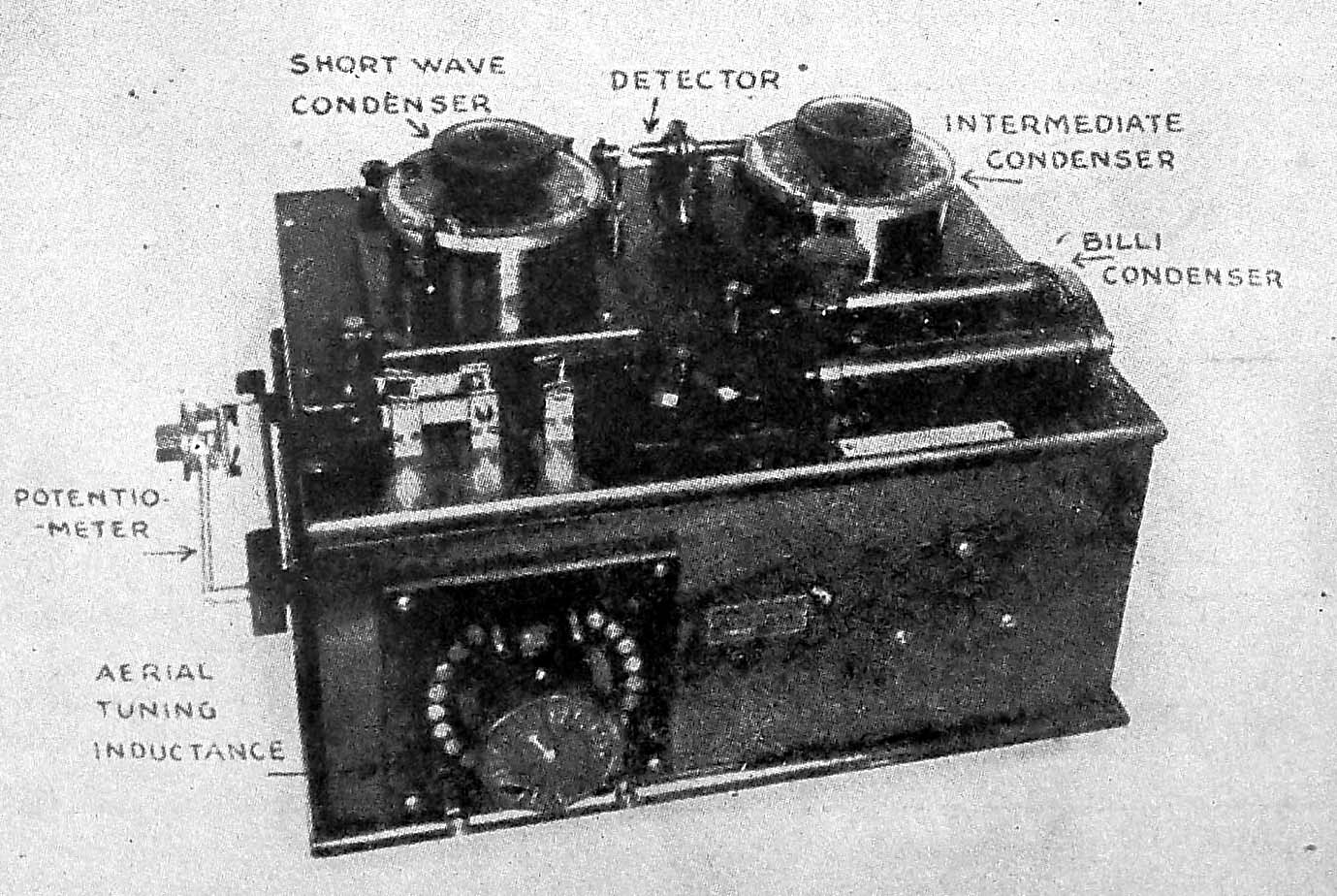
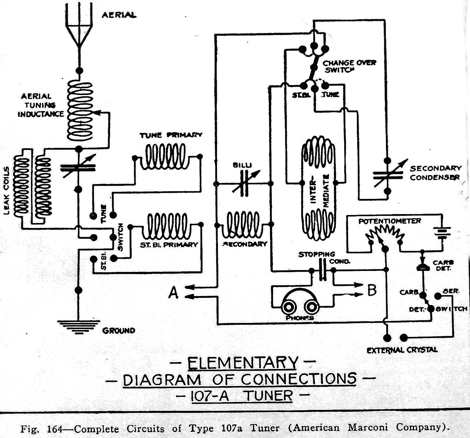
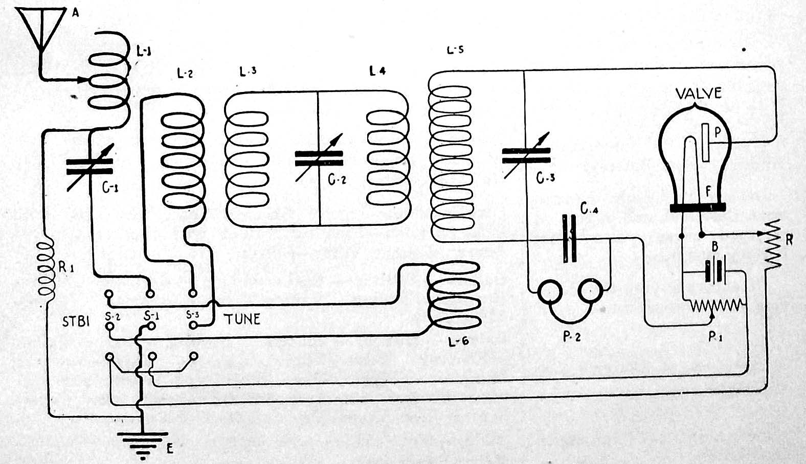
. The tuning of this receiver is unusually complicated. One would have
to post all of the pages from the Practical Wireless Handbook so that the
reader would understand what the author was talking about. At the bottom
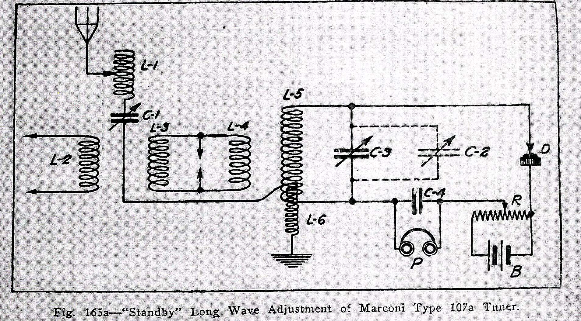
of page 147 in Practical Wreless, the author said that the 107A could
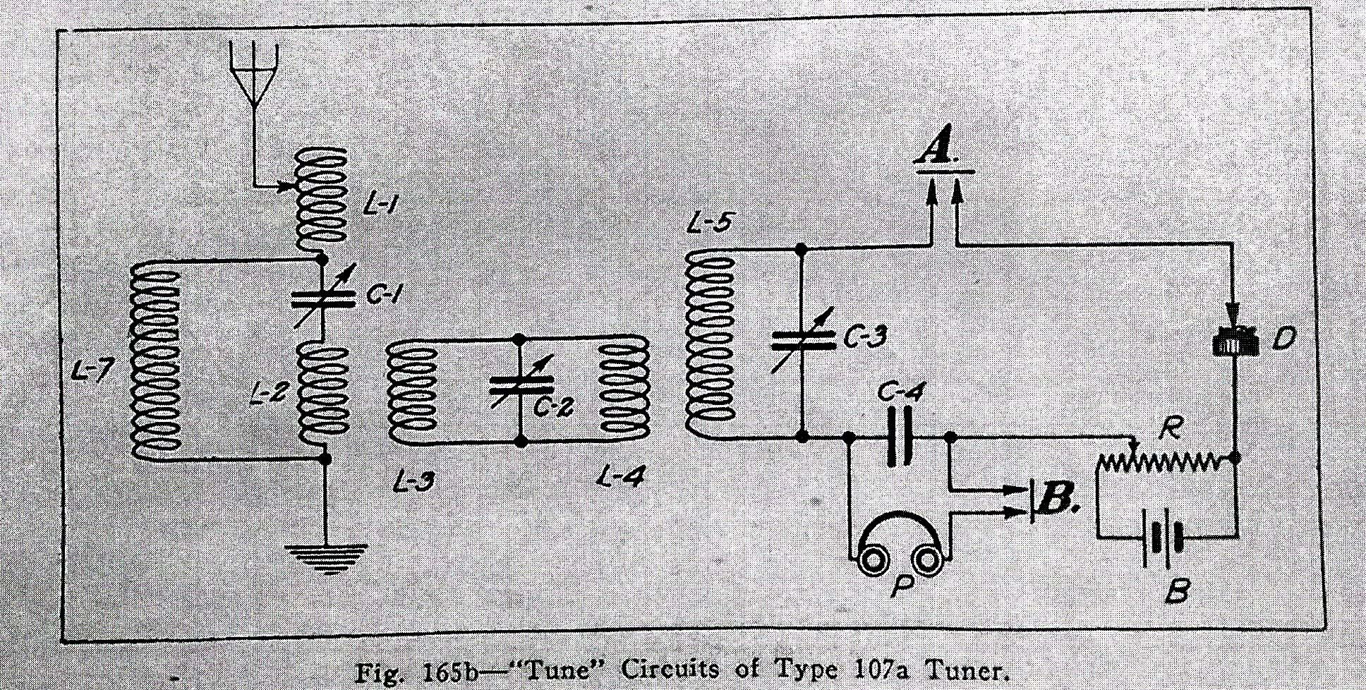
be tuned in excess of 3000 meters. This can be can only be summarized
by saying that on " Tune" , it could be tuned from 300 meters to 1000 meters,
and on "Standby", it could be tuned from 300 meters to excess of 3000 meters.
Vintage: 1917
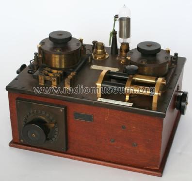
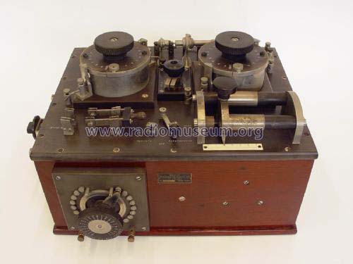
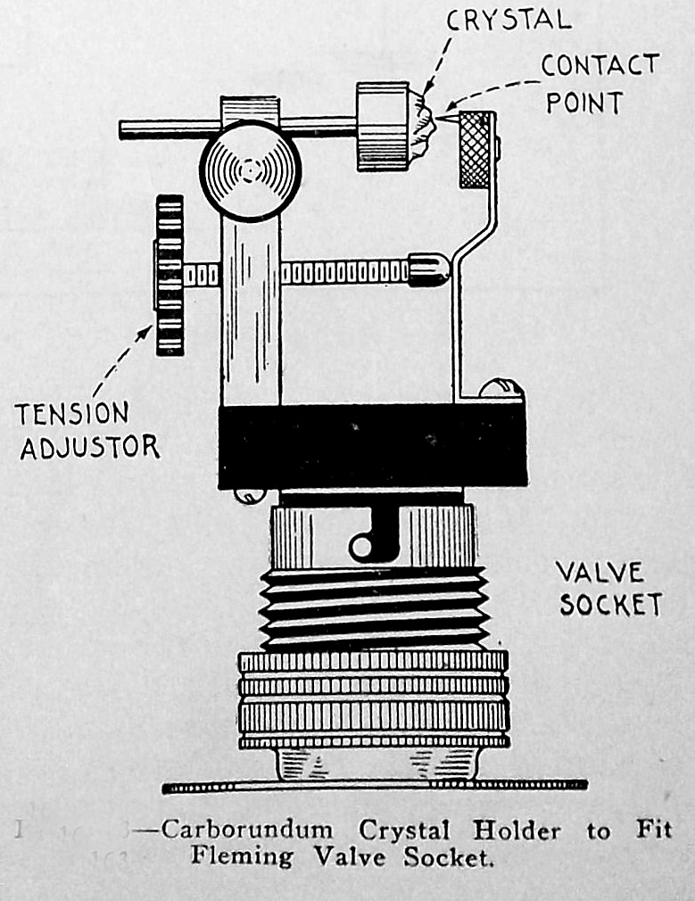
Comment: Originally
, this radio was marketed as a Fleming Valve Tuner by American Marconi.
In a conversion process, a carborundom crystal was provided which could
plug directly into the Fleming valve socket , The LF tuning range was also
extended from 1650 to 2500 meters. A spare socket on the face of the unit
was used for the storage of a spare valve.
The type 'I'
antenna switch was also used with the 107A receiver.