 |
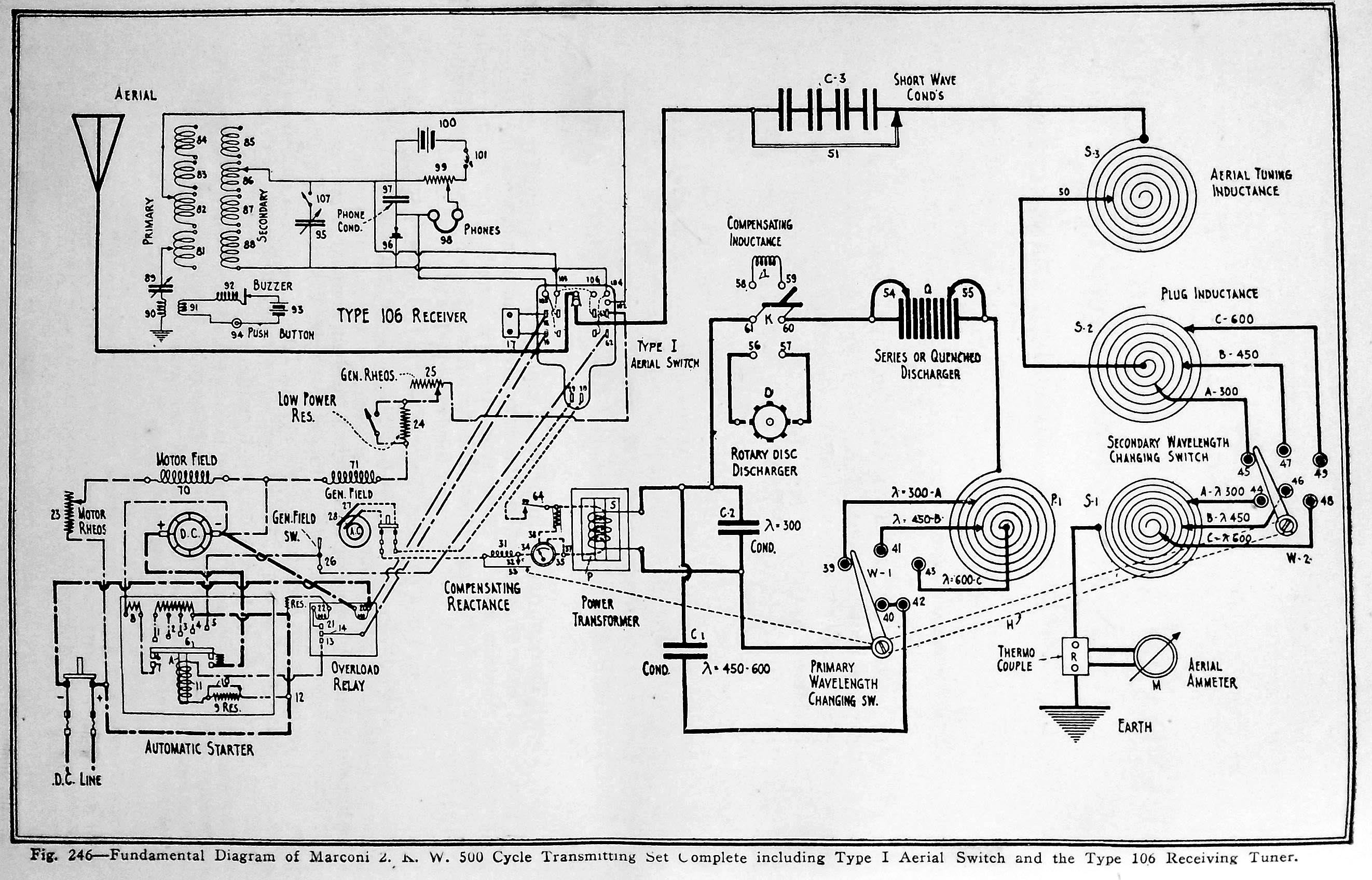
| Figure 246 - Elementary schematic for the model P4, (2 KW 500 Hz) transmitter. It includes an 'I 'switch and type 106 receiver, Click on image to enlarge, (From Practical Wireless Telegraphy) |
Wavelengths: 300, 450 and 600 metres
Power output: 2 kw; 500 Hz spark. Also has a low power mode.
Key feature: A DPDT wavelength changing switch.
Ranges: Daylight range is 450 to 650 miles . Nighttime range is 1,500 to 2,500 miles.
Comment: Practical Wireless does not give a clear description of the Panel family of transmitters other than saying they are efficient, make economical use of space, easy to install and useful as a general utility transmitter.
|
| Figure 246 - Elementary schematic for the model P4, (2 KW 500 Hz) transmitter. It includes an 'I 'switch and type 106 receiver, Click on image to enlarge, (From Practical Wireless Telegraphy) |
The P4 transmitter/receiver system comprises of the following units:1) Panel transmitter. It contains power measuring instruments. oscillation transformer,condenser, variable and plug type aerial tuning inductance,. quenched spark gap, motor and generator field theostats , wavelength changing switch, several resistance units and lastly, a compensating reactance regulator.,
2) A Crocker-Wheeler or General Electric 2 kw 500 HZ motor alternator with a synchronous rotary spark mounted on the alternator shaft. The motor-alternator consists of a 4 hp, 110 volt DC motor which connects directly to a 2 KW 500 Hz alternator. The motor can operate on line voltages between 95 and 115 volts. The alternator is of the rotating armature type and whose no-load output is 350 volts . Working voltage is 140 volts.
3) A type 106 receiving tuner with a crystal rectifier and headphone..
4) Type 'I' aerial changeover switch which includes protecting the receiving apparatus from the transmitter. .
5) Type 'C' transmitting key.
6) A high voltage, closed core transformer immersed in a semi-liquid grease. . Output voltage on the transformer's secondary was 12,500 volts.
It was also expected that vessel owners provide a 60 cell battery along with a charging panel which can regulate the amount of charge.
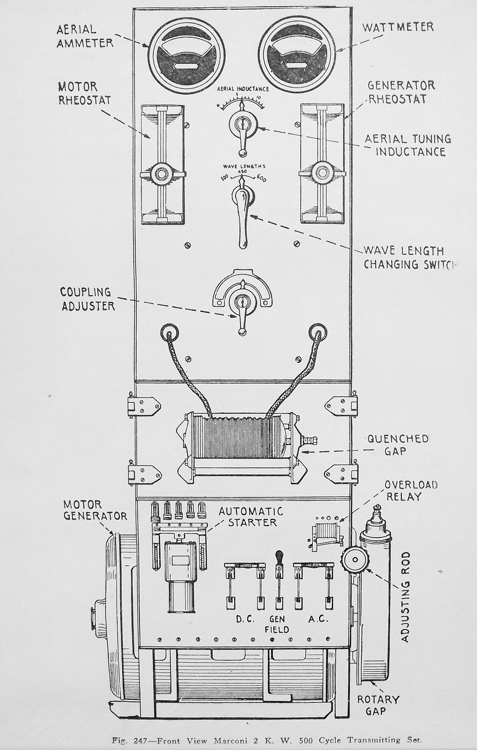 |
Figure
247 , Front panel of the P4. transmitter which also includes the motor
starter. This transmitter could become ready within 12 seconds of
being powered up, Click on image to enlarge. (From Practical Wireless
Telegraphy)
The P4 transmitter
is fitted with a synchronous rotary gap having 30 sparking
points It is also fitted with a quench spark gap which consists
of 15 plates mounted in a insulated metal rack. It is presumed that the
transmitter could be used with either spark mode by the use of a DPDT switch.
|
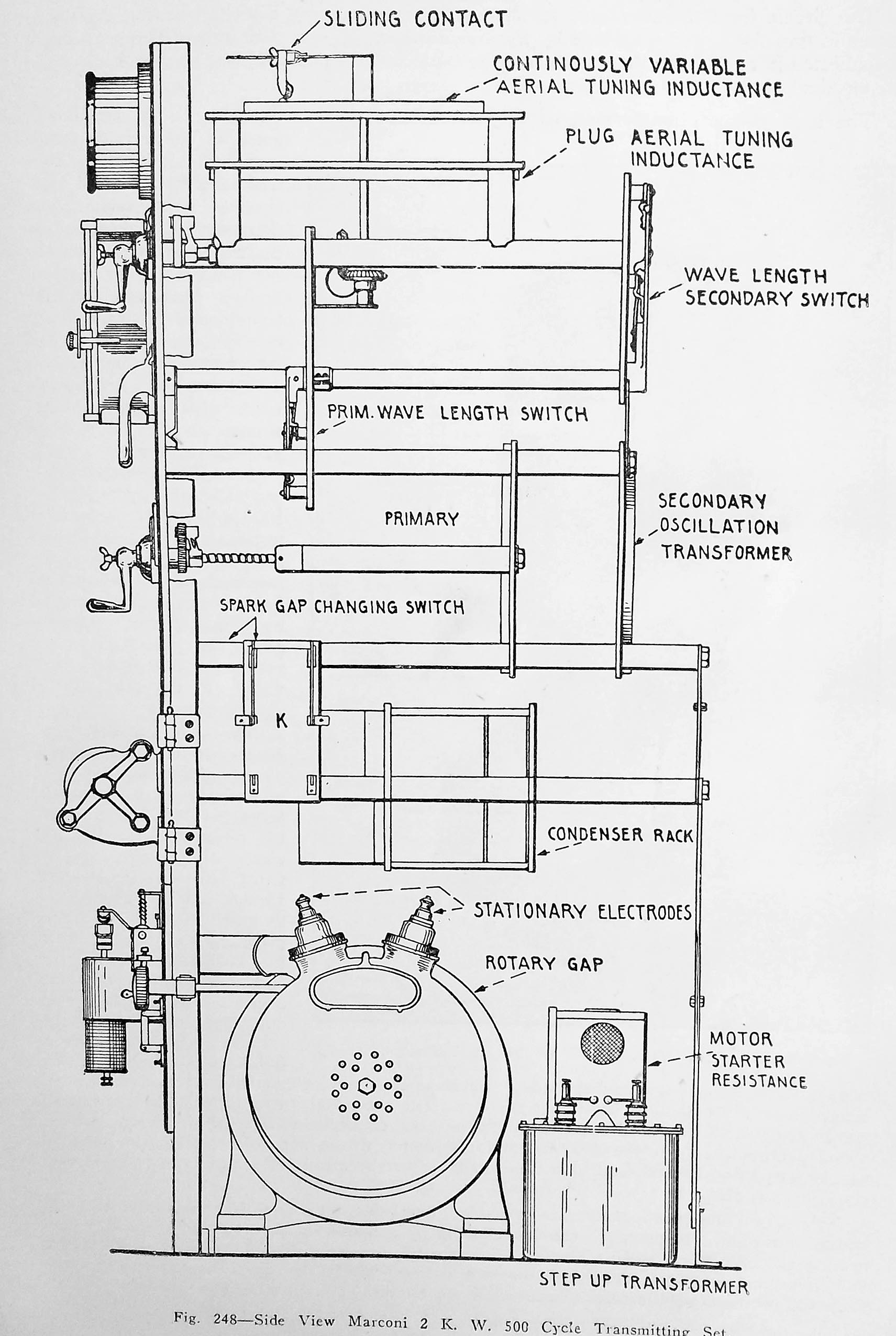 |
Figure
248 , Side view of the front panel of the P4. transmitter . Click on image
to enlarge. (From Practical Wireless Telegraphy)
At the time of design,
it was a government requirement to have a low power mode for transmitters.
To facilitate this, only one or two gaps of the quenched discharger were
used. The description from the source material does not mention how
much power is fed to the antenna in low power mode.
|
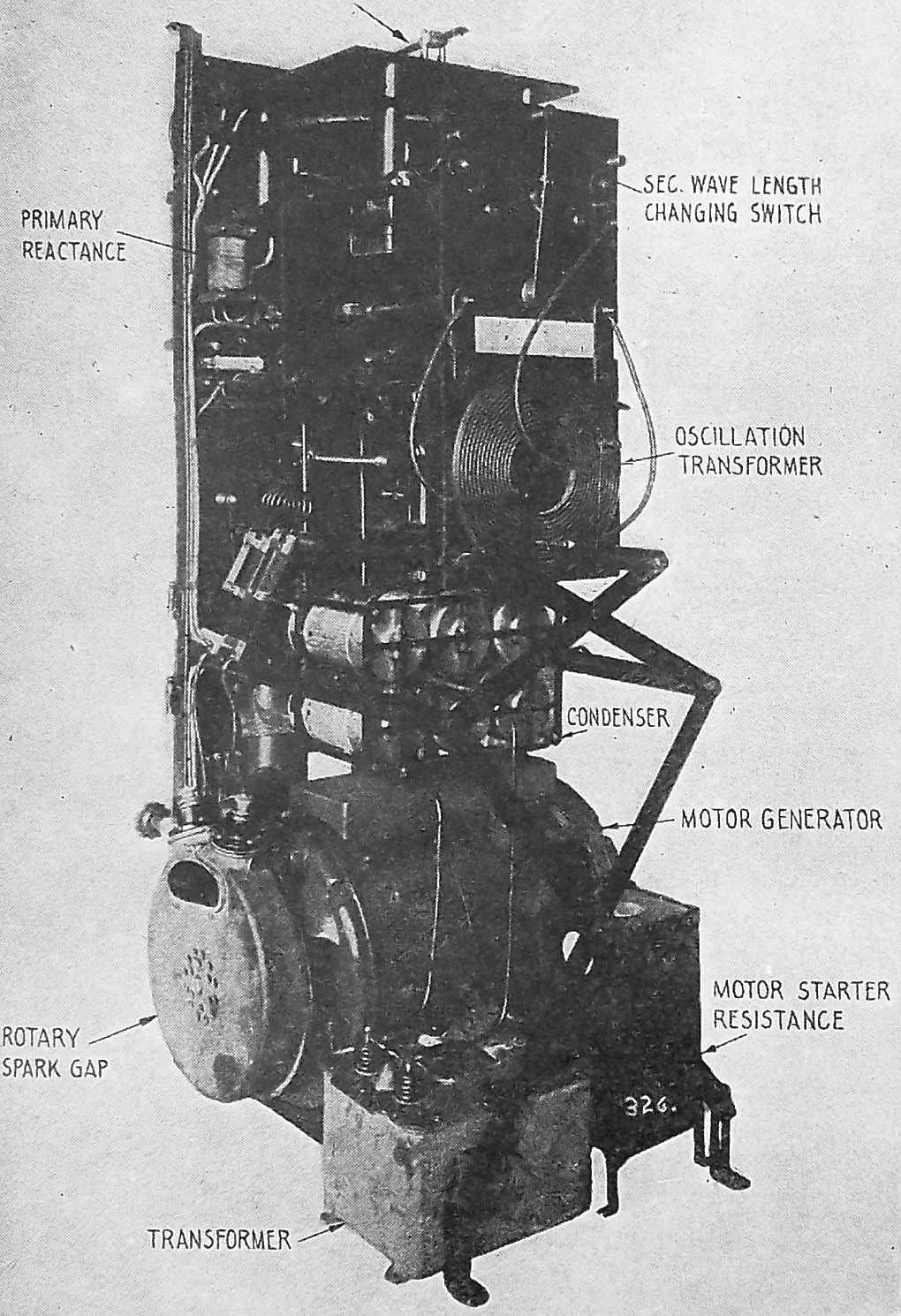 |
Figure
249 , Rear view of the P4 transmitter . Click on image to enlarge.
(From Practical Wireless Telegraphy)
The transmitting condenser comprises of six copper plated glass jars each having a capacity of .002 uf . Three condensers are connected in parallel when operating on 300 meters. For 450 and 600 meter operation, all six condensers are connected in parallel. The aerial ammeter is a direct current instrument rated at 0- 20 amps. Its terminals are connected to a thermocouple which is in series with the antenna. |
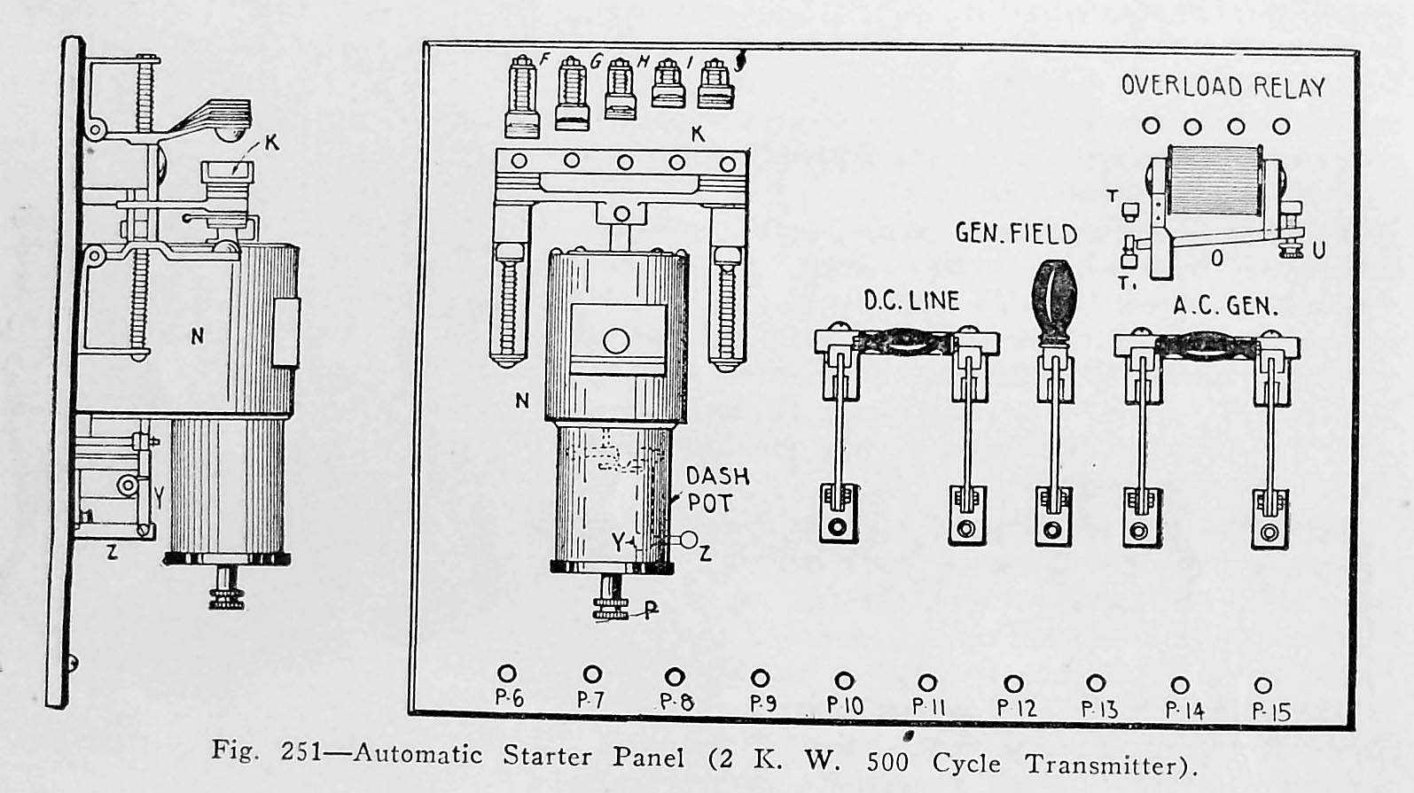 |
Fig 251 - 2 kw 500 cps front and side views of the Automatic Starter Panel. Click on image to enlarge, (From Practical Wireless Telegraphy) |
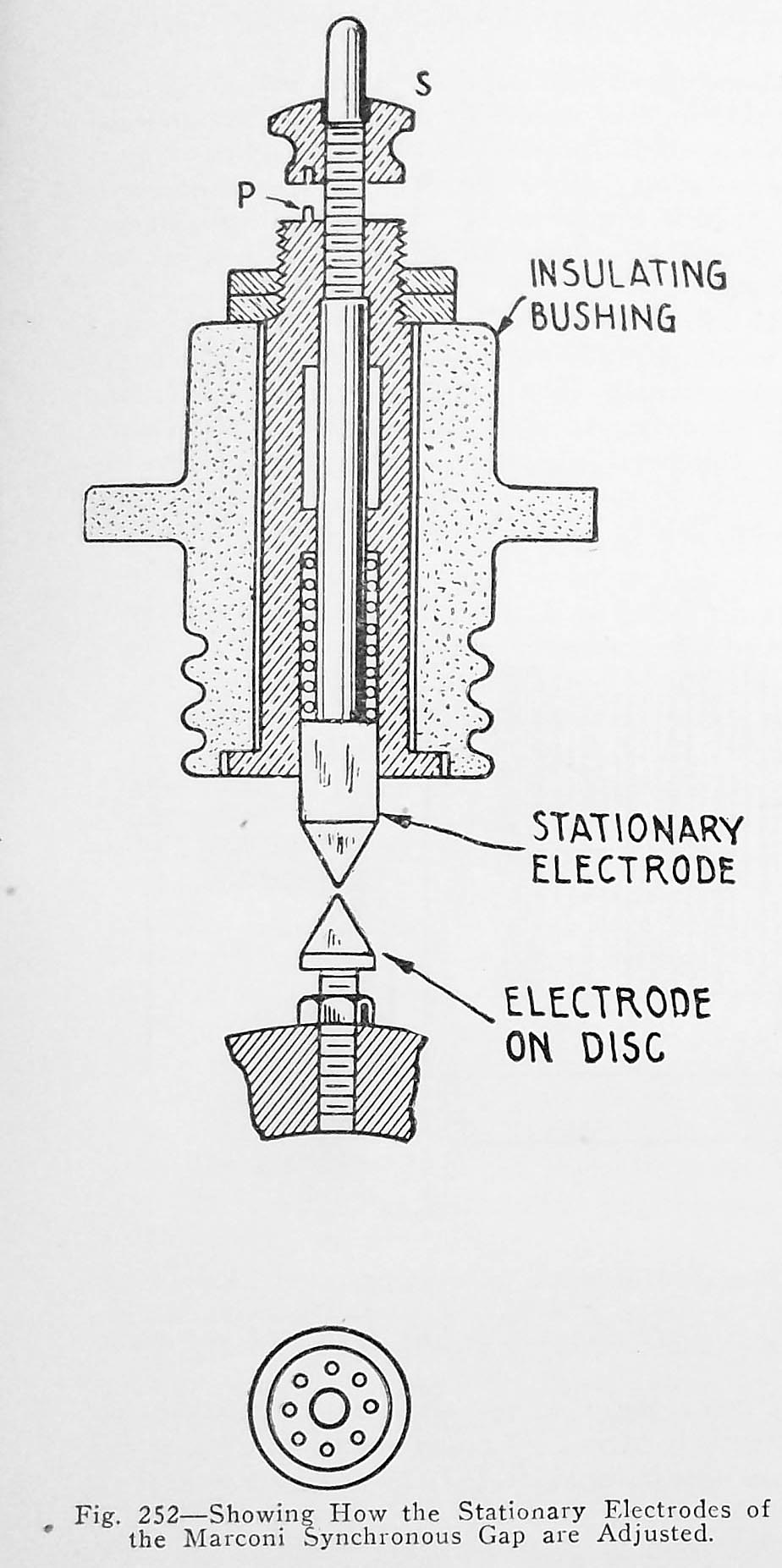 |
Fig 252 - 2 kw 500 cps electrode adjustment detail for the synchronous gap stationery electrode. (From Practical Wireless Telegraphy) |
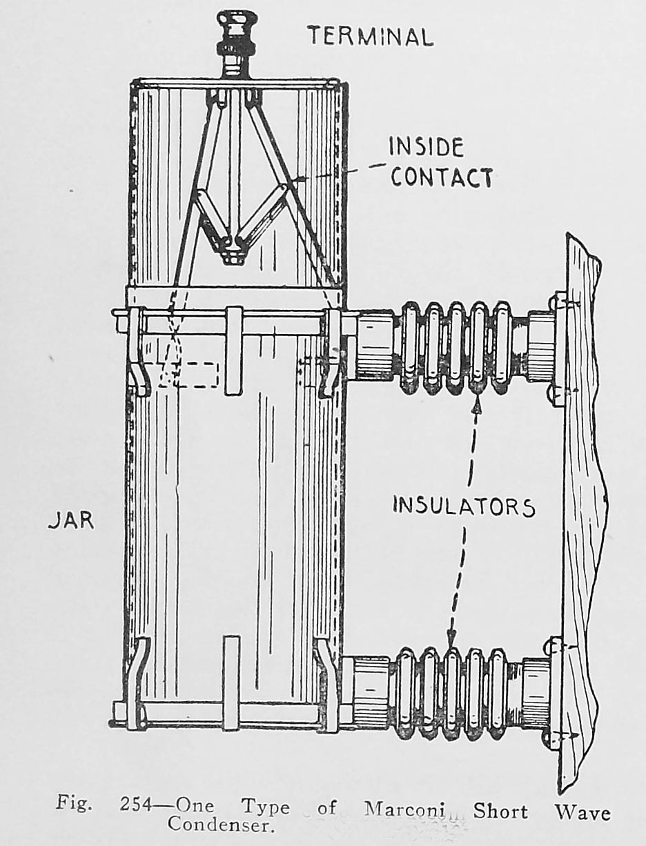 |
Fig
254 2 kw 500 cps. This is one example of a short wave condenser used
in Marconi transmitters. (From Practical Wireless Telegraphy)
Two in series= .001
uf
|
 |
| Fig 67b. 2 kw 500 cycle Crocker Wheeler motor-alternator assembly. From Practical Wireless Telegraphy) |
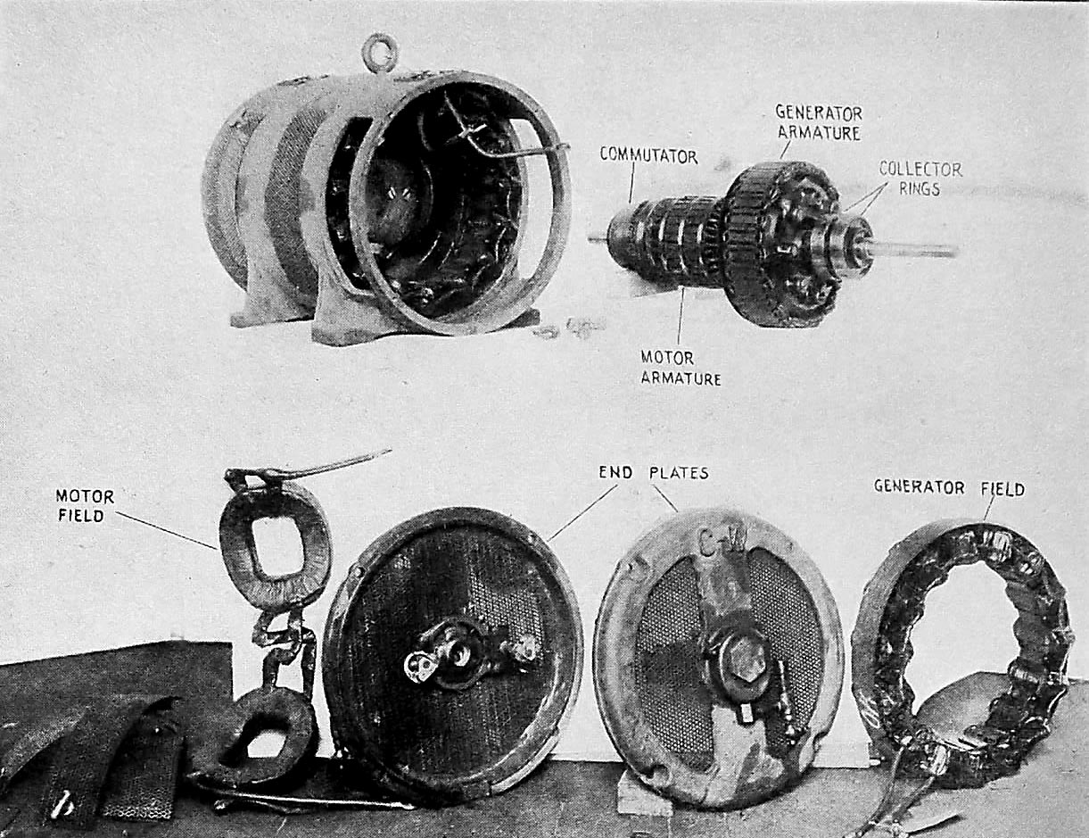 |
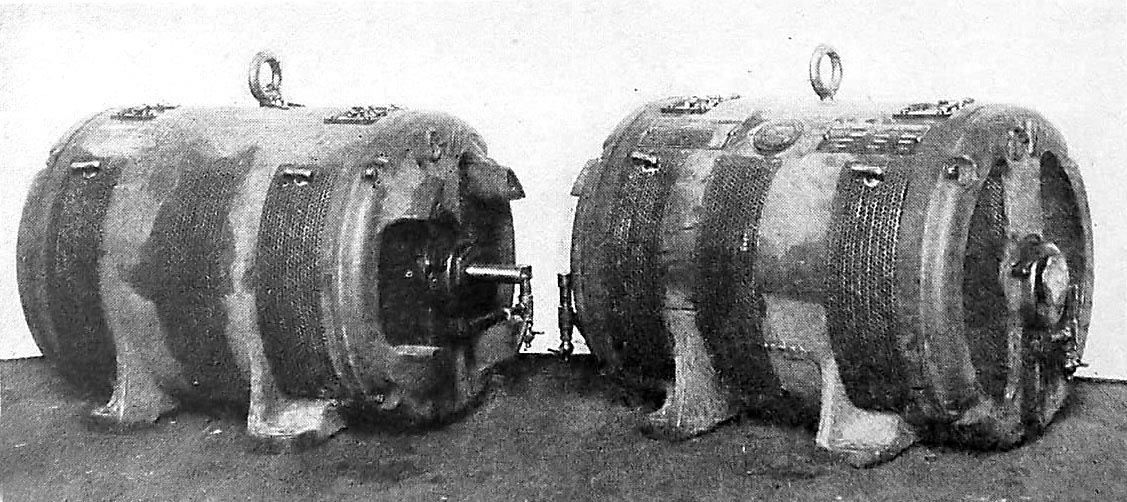
| Fig 67a
2 kw 500 cycle Crocker Wheeler motor-alternator disassembled. (From
Practical Wireless Telegraphy)
The generator has 30 field poles and the motor has 2 field poles .The armature revolves at 2,000 RPM, hence there are 33 1/3 revolutions per second which multiplied by 30 (the number of field poles) gives 1,000 alternations of current per second. Since two alternations of current constitute a cycle, the frequency of this alternator is 500 cycles per second. Power input to the motor is 29 amps at 110 VDC. |
Contributors or Credits:
1) Lewis Bodkin
2) Practical Wireless Telegraphy by Elmer E. Bucher, copyright 1917, Oct. 1918 edition
Oct 18/21