 |
| The P5 quenched gap spark transmitter was designed for shipboard use. Just above the M-A set, is the closed core transformer whose output is 14,500 volts. (Source: Manual of the Marconi Institute). |
Frequency range 300, 450 and 600 metres
Power output: 0.5 kw; 500 Hz spark
Range: Daylight range is 250 to 400 miles. Nigh time range is 600 to 1,500 miles
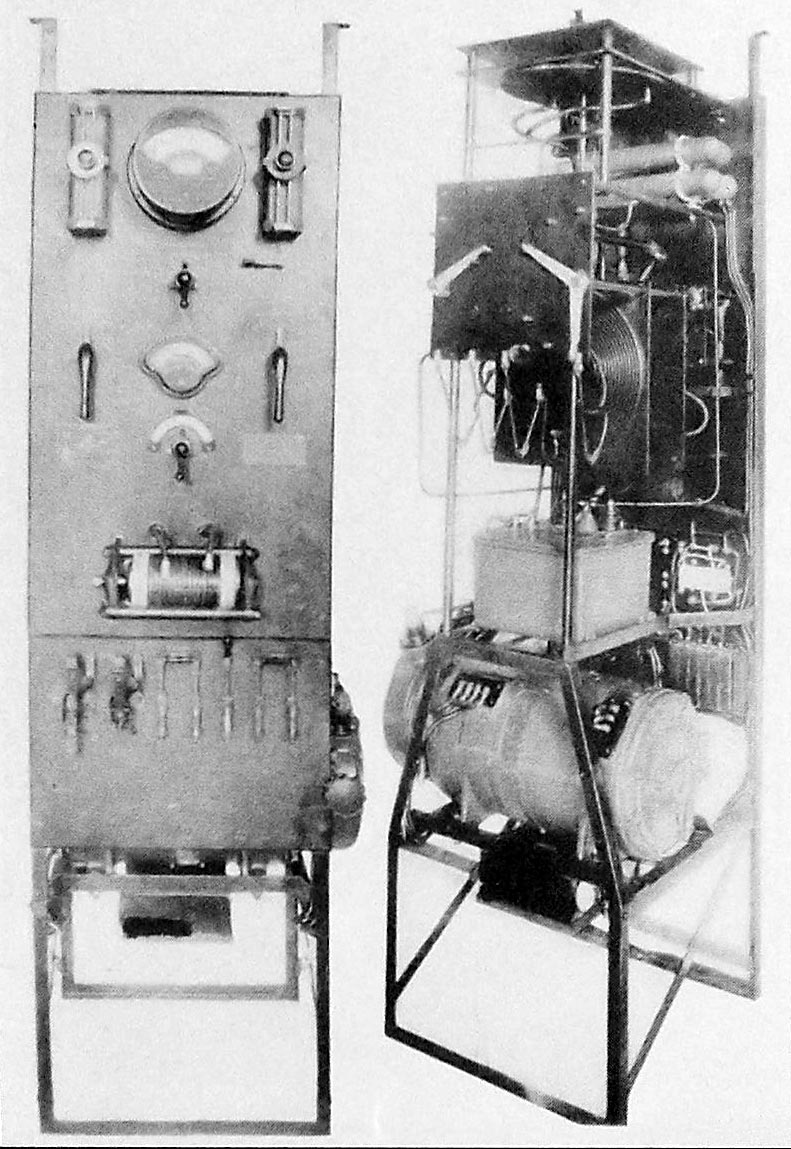
Comment: In many respects, the P5 transmitter duplicates the P4 functions except for some mechanical modifications. The motor -alternator is now mounted on the panel frame. The motor alternator comprises of a 110 volt DC motor directly connected to a 120 VAC 500 Hz alternator. The motor is designed to work with DC mains from 95 to 115 Volts. Open circuit voltage of the alternator is approximately 350 volts, It drops to 120 volts with the key down. Motor speed is 2,500 RPM..The P5 transmitter system also includes:
1) A type 'I" aerial switch
2) Type 106 receiving tuner
3) Flush switch for starting and stopping the motor -alternator from a distant point.
4) Aerial ammeter 0 to 10 amps
5) Wattmeter 0 to 750 watts.
|
| The P5 quenched gap spark transmitter was designed for shipboard use. Just above the M-A set, is the closed core transformer whose output is 14,500 volts. (Source: Manual of the Marconi Institute). |
| Figure 257 . 500 watt 500 cps transmitter front panel controls and dimensions. Click on image to enlarge. (From Practical Wireless Telegraphy) |
 |
| Figure 258 . 500 watt 500 cps transmitter side view. Click on image to enlarge. (From Practical Wireless Telegraphy) |
 |
Fig 259. 500 watt 500 cps transmitter rear view. Click on image to enlarge. (From Practical Wireless Telegraphy) |
| Fig 260, 500 watt 500 cps transmitter. Front and side views of the Automatic Starter panel . Click on image to enlarge. (From Practical Wireless Telegraphy) | |
 |
Fig 255. 500 watt 500 cps transmitter - fundamental wiring diagram of the autostarter. Click on image to enlarge. (From Practical Wireless Telegraphy) |
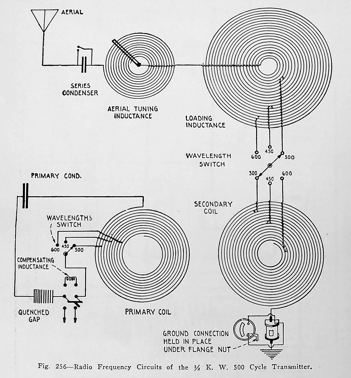 |
Fig
256. 500 watt 500 cps transmitter elementary RF circuits. Click on image
to enlarge. From Practical Wireless Telegraphy)
The transmitter condenser consists of four copper plated Leyden jars connected in parallel. Each having a capacity of .001 uf . |
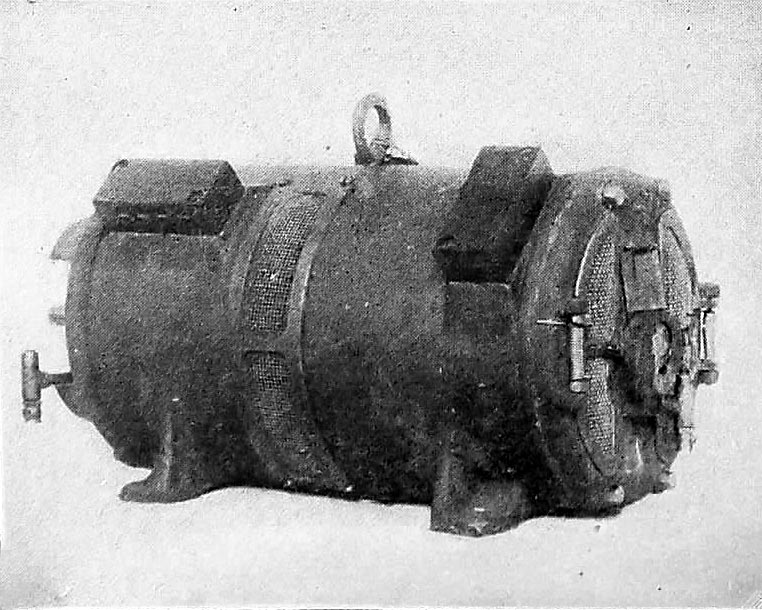 |
| Fig 67D. 1/2 kw 500 cycle motor-alternator complete, The motor is rated at 4.2 hp, (From Practical Wireless Telegraphy) |
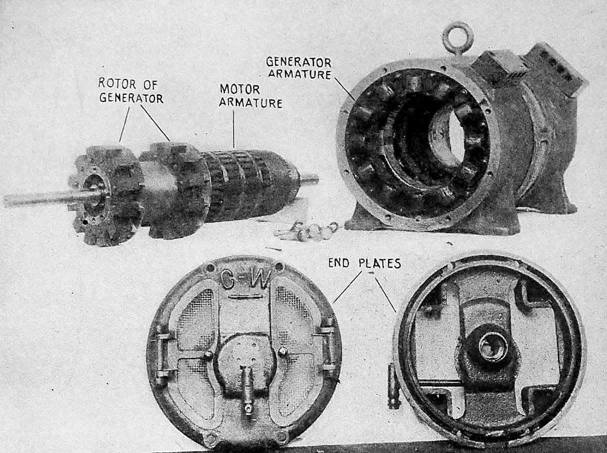 |
| Fig 67C - Detailed view of the 1/2 kw 500 cycle motor-alternator. Click on image to enlarge. (From Practical Wireless Telegraphy) |
Credits or References:1) Practical Wireless Telegraphy by Elmer E. Bucher, copyright 1917, Oct. 1918 edition
2) Lewis Bodkin
Oct 18/20