43 SET (TRANSMITTER) 
The  43 set is not mentioned in any of the Canadian Army 1944 documentation which appears in this web page. Because this is a very rare set, this document makes a perfect home for it. The 43 set was used by 4 Co First Canadian Army Signals. Canadian Army Overseas (CAO) based in London, had at least one hundred type 43 sets on strength in 1944

The 43 set is called "Transmitter Canadian No. 43 Mk II. The "Temporary working instructions" are H.Q.S. 9070-12-11 (DECD) dated 15 June 1943. The final manual was produced in 1945.  The entire 43 set is usually referred to as the  W.S. Canadian No. 43 Mk II. Philips (?)  produced the transmitter portion. It was designed to fit in a 30 HWT truck along with a generator.

Jim Fleming provides this additional description of the 43 set:

"The final manual that I have is HQS9070-12-11 (DECD) ZA/CAN5911  dated March 3 1945. This manual is much more comprehensive than the interim version.

The transmitter has two 813s in parallel in the final and the oscillator, modulator, multiplier and drivers are all 807s. The transmitter frequency range is 2 to 5 MHz and 5 to 12 MHz in two ranges. The power output is 250 watts on RT. and MCW and 500 watts on CW. The total weight (transmitter and power supply) is 610 lbs. The power supply is a separate unit and is pictured under the transmitter. The transmitter has separate VFO oscillator, multiplier and final tuning sections and controls for each range. The right hand side of the transmitter is used with the lower range 2 to 5 MHz and the left hand section is for the higher range 5 to 12 MHz. The tubes in the oscillator, multiplier and final are common to both ranges and the range selection switch switches them back and forth. Only one range can be used at a time, but the two frequencies can be pretuned and switched instantly. There is also an optional crystal oscillator adaptor which my unit contains.

The modulator is controlled by either push to talk or voice activated control and is a single 807 using grid modulation of the two final 813s. The manual goes into significant detail regarding the installation on a 30 cwt Lorry complete with a 15 cwt trailer. The installation had a 12 ft, 16 ft and 36 ft whip antenna along with the capability to connect long wire antennas when stationary. (there is a note discouraging the use of the 36 foot whip while in motion). The entire system was designed to work with the same field devices (remote telephones and keys) as the 19 sets."

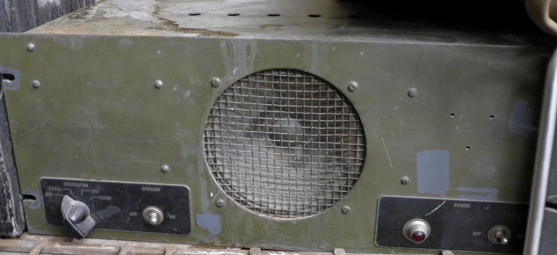
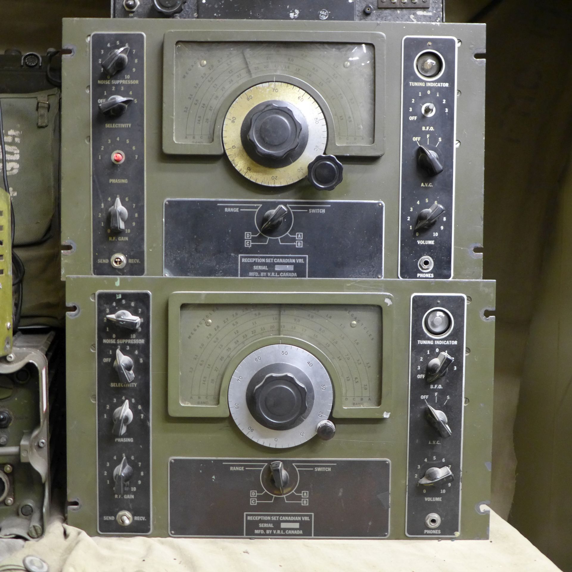
The companion receiver which forms part of the 43 set was the Vancouver Radio Labs VRL250 or the Stewart-Warner RPA-3" These are discussed separately below.


043_01a_frontview.jpg
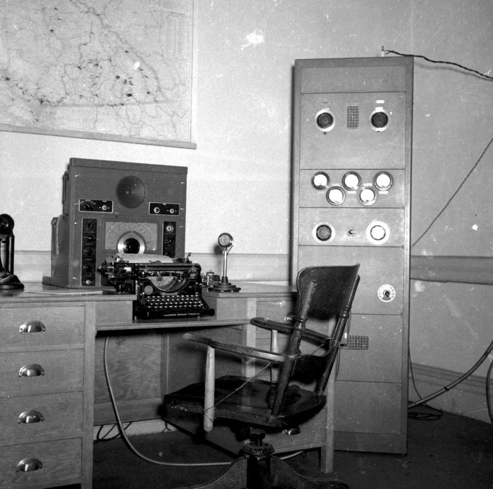
Front view of 43 set. This example appears to have never been used.
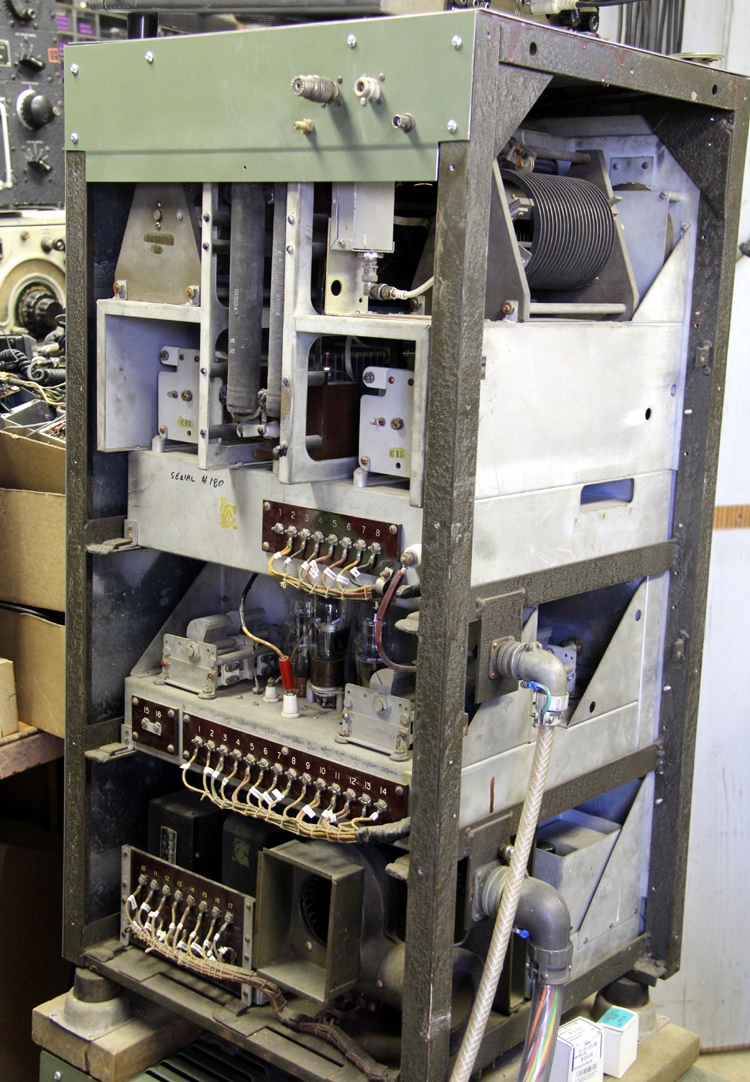
43 set rear view. It  has two oscillators and two out put sections using a pair of 813s.  It is believed that one oscillator and output tube is for a higher frequency range than the other. The original RF connectors were feed-through insulators on the top just like the AT3. These were removed and replaced with type N connectors. 
043_03_rfdeck.jpg
43 set RF amplifier deck. The transmitter also contains a dummy load
All photos in this table by Jim Fleming VE3PBJ
RECEIVER PAIRING
 
VRL 250 RECEIVER

The Vancouver Radio Labs model VRL 250 wais the suggested companion receiver for the 43 set.  Manuals for the VRL are titled as VRL or VRL 250. Both of these are  identical in all respects.  So the proper designator should be VRL 250. One  interesting feature of this receiver is the dual AVC system  - one for the RF and one for the IF. A service manual for the receiver can be found at:  Reception Set Canadian VRL

Operators of the First Canadian Army Signals expressed dissatisfaction with the VRL250 when it was first issued to them. However, it was found that once operators were trained  and used the receiver for 50 to 100 hours, they were unanimous in their preference for the VRL over their existing National HRO receivers. The inclusion of a crystal calibtator and not having to change a coil set  when charging bands was a great feature along with not  having to to use a logging scale. At First Army HQ, the VRL250 was able to receive signals that were unintelligible on the HRO.

There were also some complaints regarding dial backlash since early versions of the receiver lacked a vernier lock, This was later remedied by the imclusion of a vernier lock, The main tuning control operates freely when the small vernier tuning knob is in the “RELEASE” position (down and to the right). When the vernier tuning knob is in the “LOCK” position, it engages the circumference of the main tuning knob skirt, thus preventing the main tuning knob from being turned. In this position, the frequency can only be adjusted by turning the vernier knob.

At one point, there were two VRL250 sets being issued with each 43 set.

vrl250 spkr rack.jpg
The speaker rack was mounterd atop the receiver. Click on image to enlarge. (Photo by Graeme Wright)
250 001.jpg
Two VRL receivers stacked one on top of another. Click on image to enlarge. The SPARC Museum has three examplles -  two green ones and an orange one. (Photo by Graeme Wright)
vrl nameplate.jpg
VRL nameplate. It seems luke there is insufficient space to emboss the full designation of VRL 250. Serial 58 is the other known unit besides this one. (Image by Tom Brent)

 
vrl manual cover2.jpg
VRL 250 manual cover dated 1945. The VRL 250 manual was published in two 5.5” x 8.5” booklets. (Provided by Bruce MacMillian) VRL manual cover dated May 1944. (Provided by Tom Brent)

 
vrl250 controls.jpg
VRL250 controls. Click on image to enlarge. Some of the early VRLs didn't  have a vernier/dial lock. (Provided by Bruce  MacMillian)
On one of the VRL250 manual covers, there is an inscription which says to "Return to CBC. Prince Rupert, BC" That CBC affiliate station was CFPR-AM m Prince Rupert operating on 1240 Hz and later moving to 800 KHz. Wonder what they were using the VRL250  for ?
vrl bc forestry service.jpg
The VRL250 in use with the BC Forestry Service. Click on image to enlarge. The transmitter has not been identified.  (Provided by Tom Brent) 
vrl250 orange cabinet.jpg
Here is "what not to do" to a historical artifact. This VRL250 (S?N 842) example is held in the collection of the SPARC Museum . A previous owner painted the radio orange. (Photo by (Gerry O'Hara)
Sometimes valuable information such as frequency usage is attached to the front panel of a receiver. That was not the case in this example. The dymo tape denotes the frequency bands of various radio servicess and likely applied by a short wave listener. Click on image to enlarge. (Photo by Graeme Wright)

 
RPA-3 RECEIVER
RPA3_SEt.jpg
Steward Warner RPA-3 receiver. 
/RPA3_NAM.JPG
RPA-3 nameplate
/Steward -W  RPA-3 Rx on left. 43 set on right pg.jpg
RPA-3 (left side) paired up with a type 43 transmitter (right side) in an army communications van.  (Provided by Dave Whiting  VA3QG)


Credits and References:

1) Jim Fleming <jim.c.fleming(at)gmail.com>
2) Tom Brent
3) Bruce MacMillian
4) Dave Whiting
5) Gerry O'Hara
6) Graeme Wright

Back to Home Page

June 17/24