 |
| 226 Schematic. Download image to enlarge. (Courtesy Handbook of Technical Instruction) |
Type: TRF with regeneration
Frequency range: 300 meters to 3000 meters (1000 KHz to 100 KHz) using the Long Wave Panel.
Vintage: 1916
Comment: Detection could be switched between a crystal or a valve.
Made by : Marconi UK
Comments:1) The crystal detector may be in the silver can at the bottom of the panel.
2) The 226 is a component part of the No.4 receiving set.Type 226A
In the type 226A, a crystal is provided for use if desired. A two-pole double throw switch is provided in the receiver to connect the crystal wIth the tuning circuit.,The receiver, type 226A, is arranged to be used with either a V24 DEV, DER of type 'R' valves.
Type 226B
In the type 226B, the construction is improved by the addition of a non-microphonic valve holder, Type 226B is intended for use
with either DER, DEH410 or DEfI612 valves.THEORY OF OPERATION
TYPE 226 RECEIVER
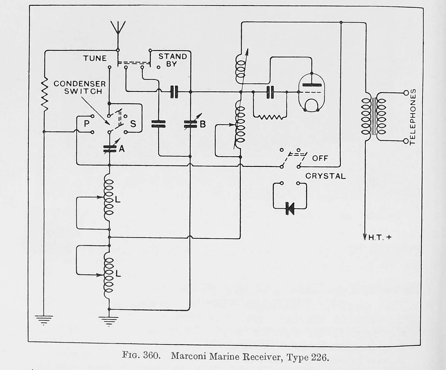
The 226 consists of a single valve, self-oscillating circuit, fitted with variable reaction and grid-condenser rectification. The wave range of the receiver is from 300-3,000 metres.. Refer to the 226 schematic in Figure 360 below.
It can be seen that the receiver consists of two circuits - the aerial circuit and the closed circuit. Each consists of a variable inductance and a variable condenser. When the Tune" " std. " switch is thrown over to the ' std.bi" position, the aerial and earth are connected to the closed circuit. The receiver is then tuned to the desired frequency by means of the comdenser and the closed circuit inductance, L
The aerial circuit can now be tuned by throwing the switch back to the" tune" position and adjusting the aerial circuit by means of the condenser A and the aerial tuning inductance, L. A switch is provided to place the condenser A either in series or parallel with this inductance.
In order to keep the adjustments reasonably constant when switching from "std.bi" to "tune," two balancing condeners are used. One is in series with the aerial in the" std.bi " position so as to make the aerial capacity very much the same for all ships, and the other is switched ,into the first circuit in parallel with the variable condenser when In the tune position, to represent
the equivalent capacity of the aerial and the first condenser in series.Since the original type 226 receiver was made, there have been two later models embodying minor improvements. Two pairs of terminals marked " Reaction" and Inductance" are provided on all the receivers. These are normally joined by links. When the long wave adapter is connected, the links are removed and a large variable inductance is joined across the impedance link terminals. and a tapped reaction coil is connected up to the reaction link terminals
Switches are fitted on the long wave panel so that the extra coils can be disconnected and the terminals on the 226 connected together when the receiver is being used for the shorter waves. There are five terminals on the right hand side of the receiver which correspond to similar terminals on the note amplifier.
|
| 226 Schematic. Download image to enlarge. (Courtesy Handbook of Technical Instruction) |
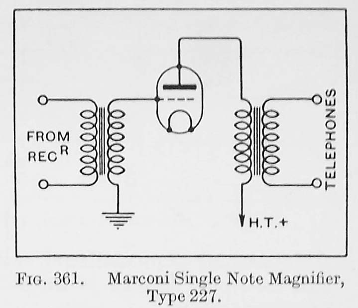
TYPE 227 NOTE MAGNIFIERThe single note magnifier, type 227, is a one-valve transformer coupled amplifier, and needs no detailed description. Its input side is arranged for connection to the headphone terminals of the receiver, and its output side is designed for use with low resistance headphones. It is adapted for clip or socket valves to match the receiver type 226.
Modifications have been introduced in the form of types 227a and 227b. In these instruments the headphones are switched back to the 226 when the note magnifier valve is switched off.
 |
| Courtesy Handbook of Technical Instruction) |
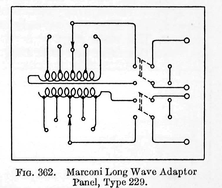
Type 229 LONG WAVE ADAPTER
The long wave adapter panel, type 229, consists of a large variable inductance, and a similar variable inductance tightly coupled to it, which acts as a reaction coil.Two double pole double throw switches are provided to enable the long wave coils to be disconnected so that the short wave coils contained in the 226 receiver alone remain in the circuit. On the very long waves, the reaction coil contained in the 226 receiver will have no effect, but on the moderate waves it can be used as a fine adjustment in addition to the reaction obtained from the adapter.
Later types, 229a and 229b, differ from type 229 only in mechanical construction. Type 229a should always be used in compunction with the receiver type 226A as the windings of these two have been arranged to suit each other.
 |
| Courtesy Handbook of Technical Instruction) |
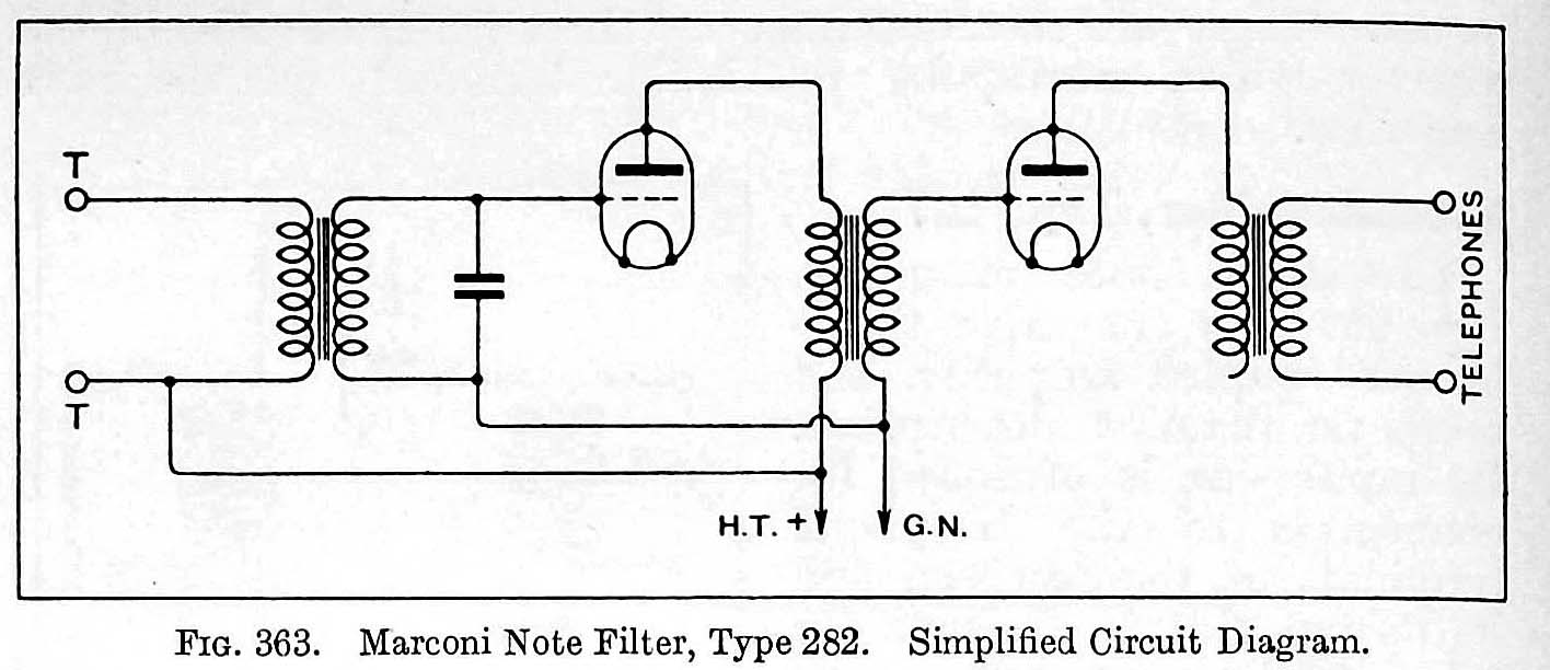
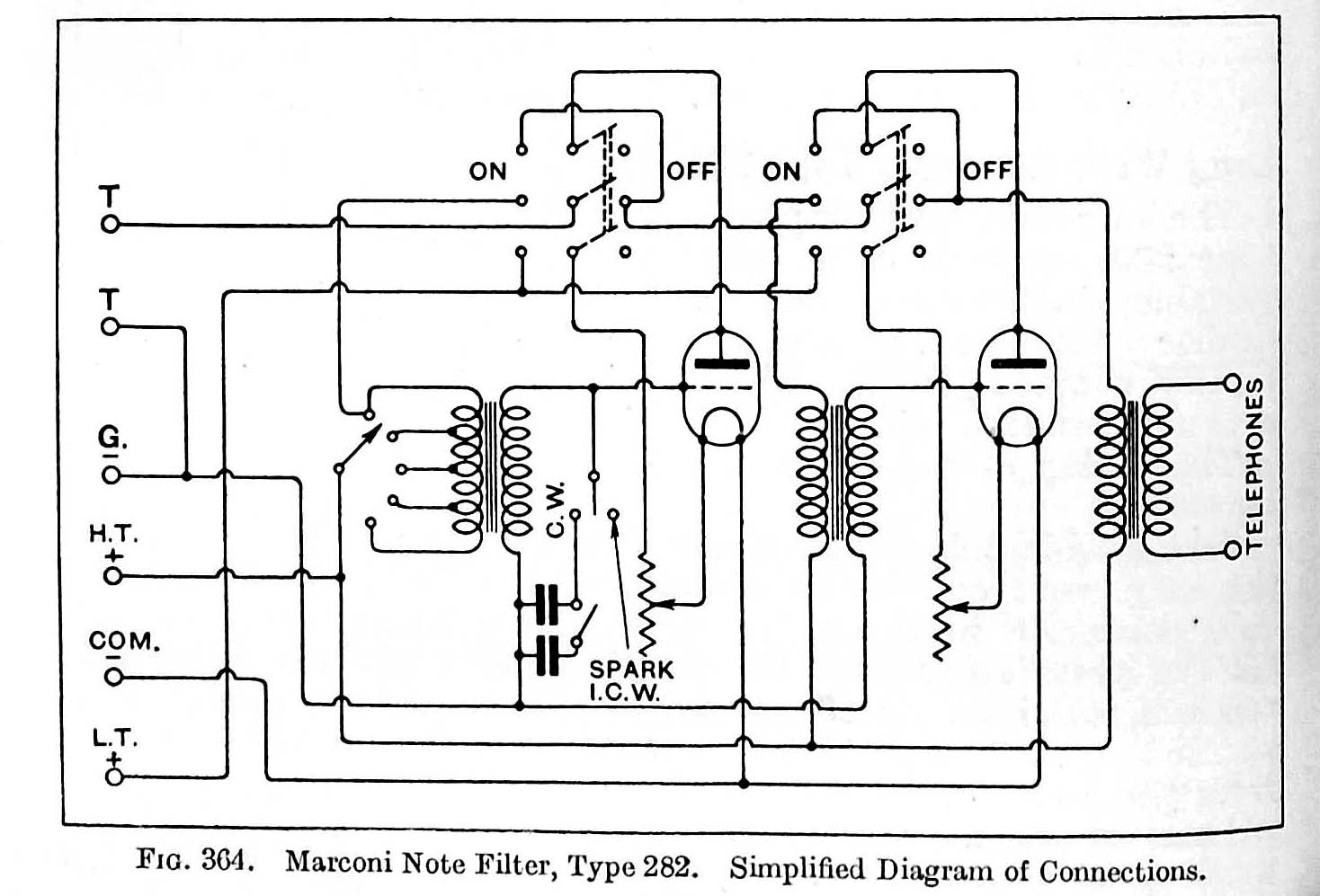
TYPE 282 NOTE FILTERThe Note Filter consists of two valves, the first coupled as a note filter and the second as an ordinary transformer coupled note magnifier. The following combinations of valves can be obtained by means of the switches:
1. Both valves can be disconnected and the headphones applied through its transformer to the 226 receiver direct.
2. Only the filter system can be connected.
3. Only the note magnifier can be connected.
4. Only the filter and note magnifier can be connected.A switch is provided to change the resonance frequency of the filter circuit, and also to alter the width of the filter band.
A simplified diagram of connections of the filter is given in Fig. 364 below. The input circuit to the first valve is merely a resonance circuit tuned to the audio frequency of the desired signal. It will be noticed that two tuning condensers are provided, one of which can be switched out if required. In this way it can be altered to resonate to a note of a different pitch.
The primary winding of the input transformer is tapped at four points. A switch is provided which makes contact with anyone of these and so adjusts the width of the resonance curve of the note filter. The less winding there is in circuit the narrower will be the band of the filter. The action of the rest of the circuit is very simple and need not be described here.
The object of the filter is to pick out one C.W. station from another on the same wavelength which may be interfering with it. It is not intended to be used for spark reception and is of no use in this connection. When using the filter for the reception of C.W. the 226 receiver should be used in the standby (standby) position only, as the note tuning will be very sharp and, if the closed circuit is used in addition ,the receiver will be very difficult to adjust.
Employed in this way the effect of the filter is very marked, and of great use in congested radio bands.
 |
 |
| 282 Note Filter schematics .(Courtesy Handbook of Technical Instruction) |
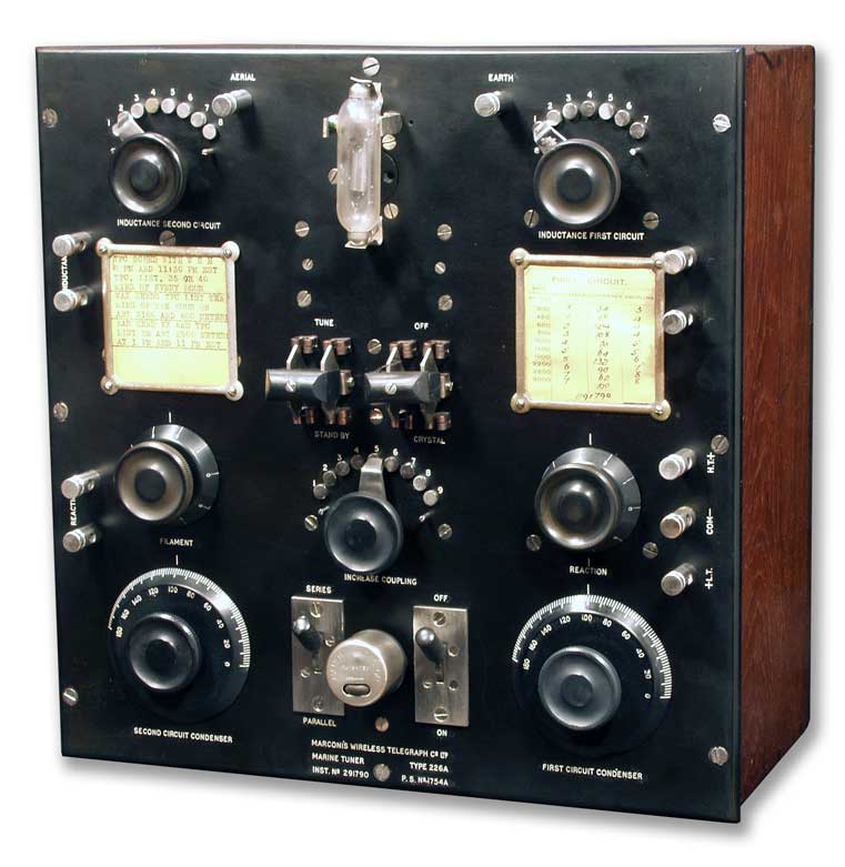 |
| 226A Receiver by itself . This example is held by the Spark Museum in Bellingham Washington. It is lacking the rightmost Note Amplifier module and a Long Wave panel on the left. |
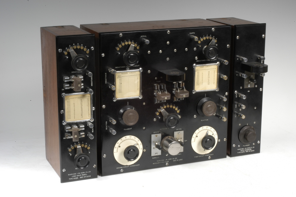 |
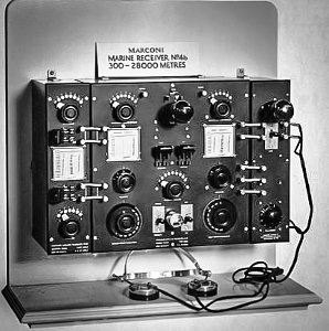
| 226B receiver. The leftmost module is the 229B Long Wave Panel while the rightmost module is the 227 Note Amplifier. This example is missing the detector valve which was situated in the top center of the receiver. (Image courtesy of the History of Science Museum in Oxford,Englamd . |
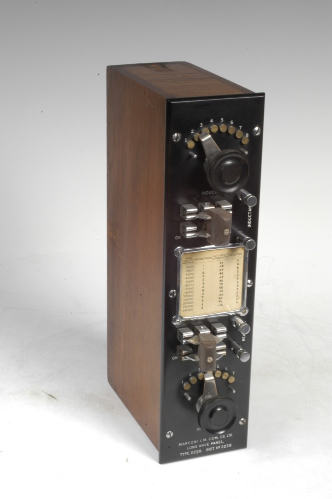 |
| Closer view of the 229B Long Wave Panel. 3000 to 26,000 metres ( 100 KHz to 11.5 KHz) The purpose of the long wave panel was to increase the frequency range of the 226 receiver. |
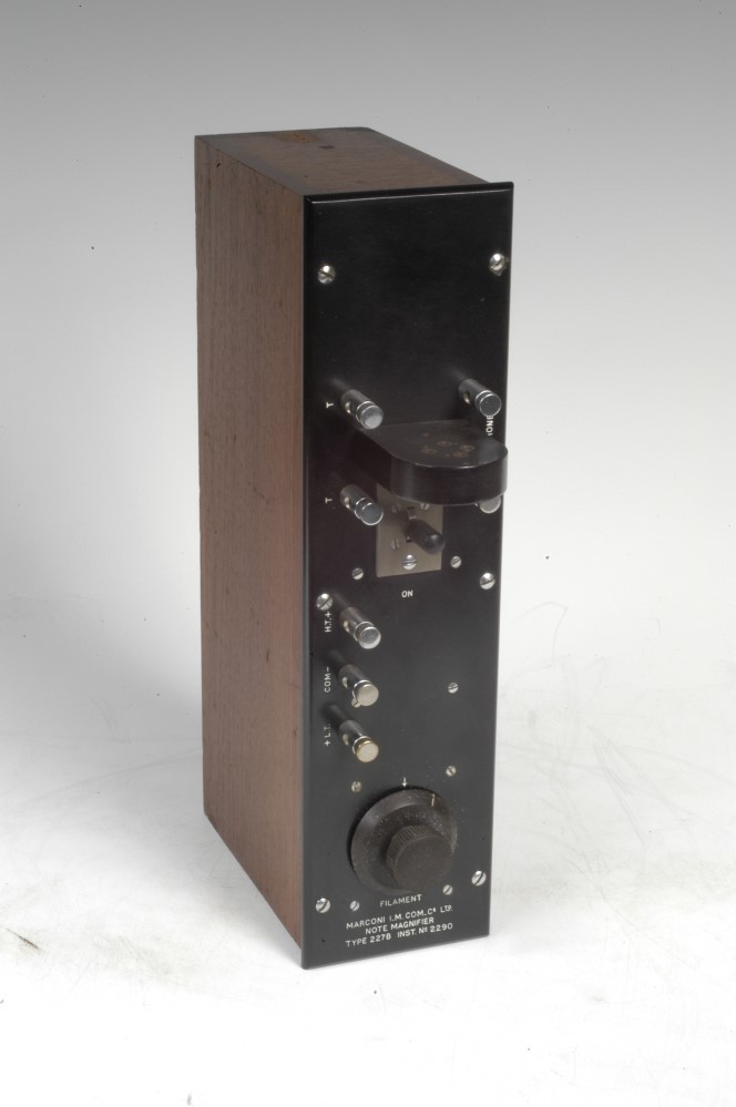 |
| Type 227 note amplifier close up. The amplifier valve, normally fitted at the top of the front panel, is missing. (History of Science Museum photo) |
 |
| Another 226B receiver photo. |
Contributors and Credits:1) Lewis Bodkin <05bodkin555(at)gmail.com>
2) https://www.radiomuseum.org/r/marconi_wi_marine_tuner_type_226a.html
3) http://www.sparkmuseum.com/MARCONI.HTM
4) 226B https://www.radiomuseum.org/r/mimmarconi_marine_receiver_226b.html
5) for For Wireless Relegraphists
Sept 16/19