 |
| Image courtesy Handbook of Technical Instruction |
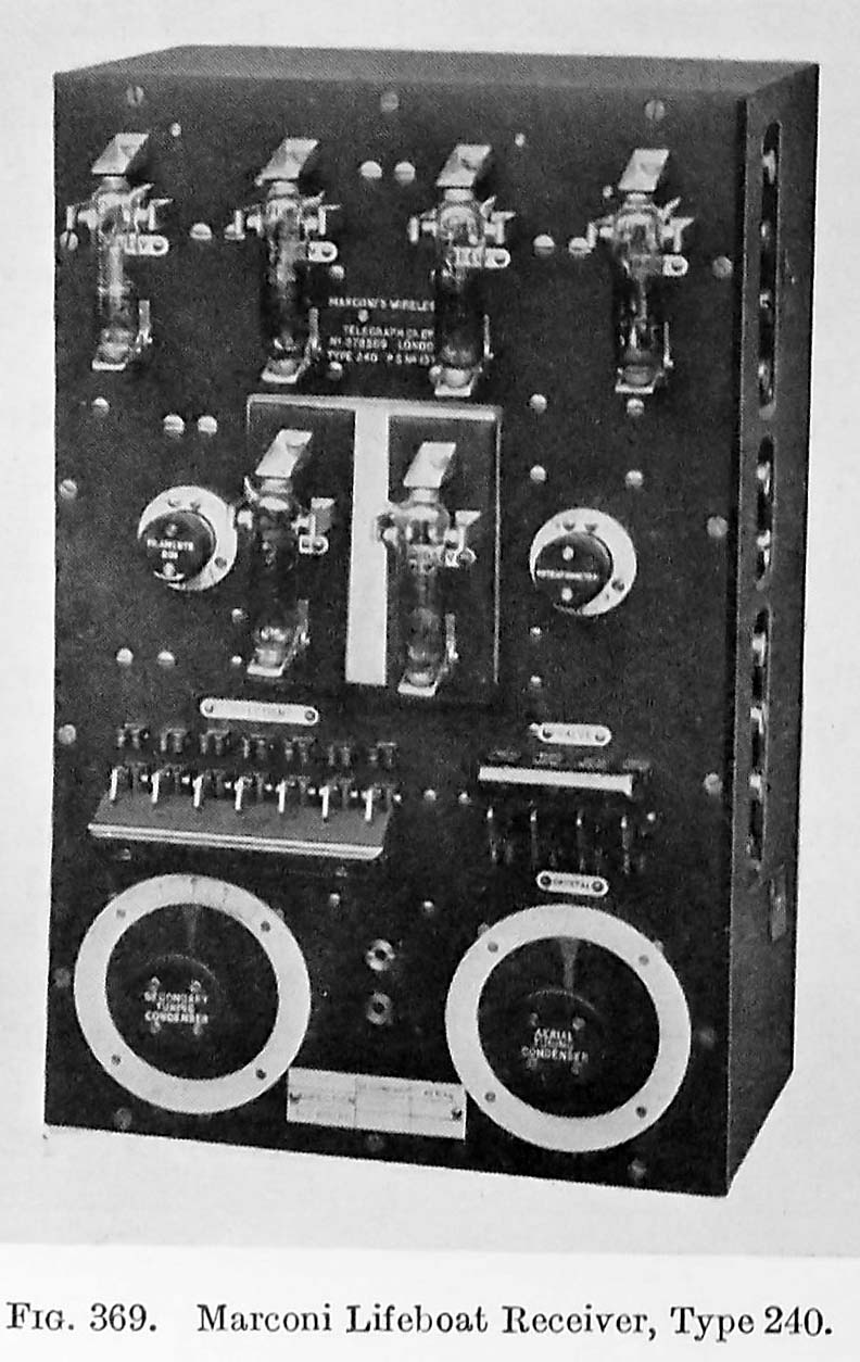
Type: Six valve receiver for use in lifeboats
The receiver shown in Fig. 369 below, is a directional one and designed for use in conjunction with a frame aerial and alternatively a vertical aerial. Four valves act as high frequency amplifiers, one as a detector, and one is a note magnifier. A crystal detector is also fitted as an alternative means of detection.
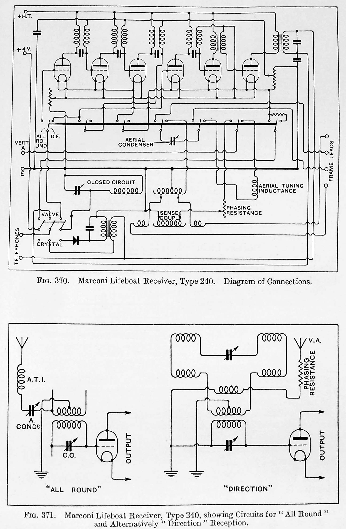
A switch is provided to enable the instrument to be used as an "all round" receiver or as a directional receiver. In the " all round" position the boats main aerial is only used. The arrangement then is that of a simple two circuit receiver, using three valves - one for HF; one for detection; and one for LF. The crystal can also he used with the switch in this position.
In the" direction" position both the vertical and frame aerials are used. The vertical aerial has a phasing resistance in series with it, which is penitently adjusted when the set is first installed. All the six valves arc then used. A compensating resistance is fitted in the set to ensure the valves retaining their correct brilliancy 'when a changeover is made from three to six valves.
Both the frame aerial circuit and the vertical aerial circuit can be tuned to the frequency of the desired signal. The adjustment of the vertical aerial circuit will he found to be approximately the same as for the " all round" position. If. the frame aerial leads are not connected as marked, the sense will be reversed.
|
| Image courtesy Handbook of Technical Instruction |
Download image to enlarge. (Courtesy Handbook of Technical Instruction)
Contributors and Credits:1) Lewis Bodkin <05bodkin555(at)gmail.com>
2) Handbook of Technical Instruction for For Wireless Telegraphists
Sept 21/19