Type: Fixed frequency receiver for DF purposes
Frequency Range: 6 meters (50 MHz)
Operational range: 100 miles.
Accuracy: +/- 2 degrees at 100 miles
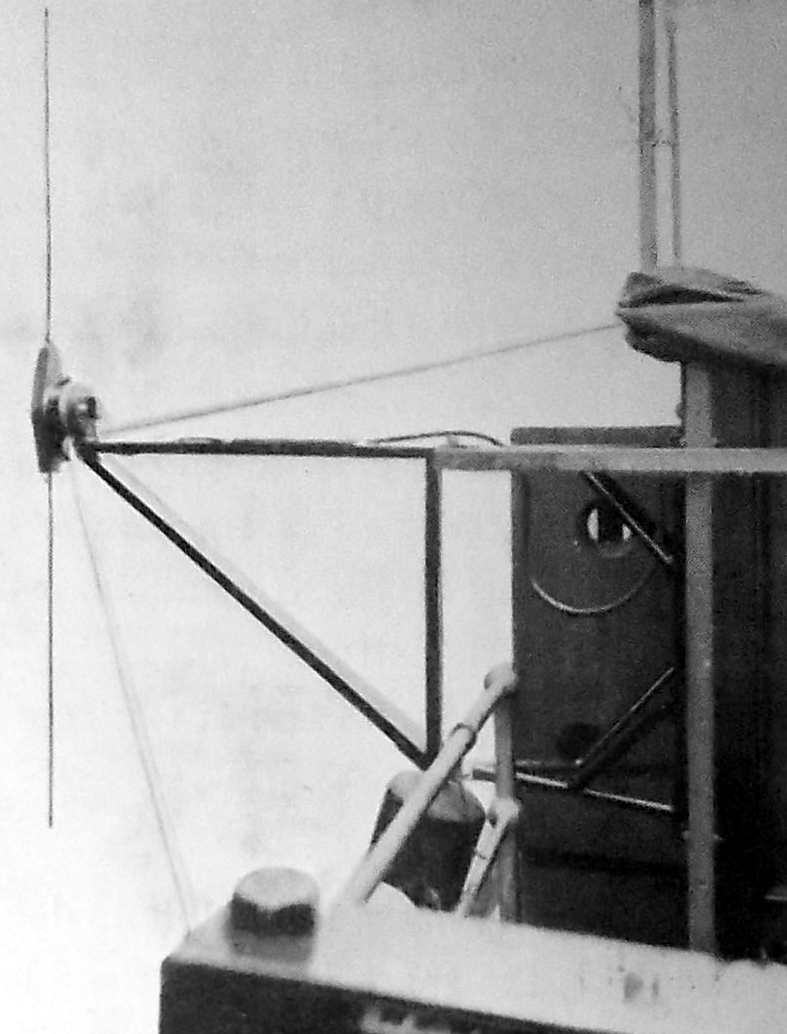
Antenna type: Crossed loops occupying some 200 to 256 square feet of
area. .
Circa: 1923
Power level: 250 watts,
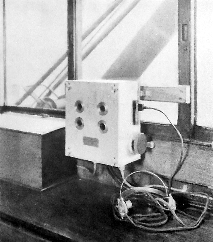
The receiver does not require operation by a skilled telegraphist. The
instrument must be permanently tuned,
and all that is required to bring it into operation is to switch on
its receiving valves. If the receiver is switched
on when the ship is anywhere near the revolving beam transmitter. two
of the letters transmitted by the beam
will be heard. and the bearing of the transmitter will obviously lie
between the two points represented by the letters.
These single letters are sent out at a speed equivalent to 12 words
per minute and at this speed they are very easily
distinguished after a little training.
A document on the receiver presents a very confusing explanation on
how to take a bearing.
"In order to make it possible to determine he bearings with a greater
degree of accuracy, the space between the" long"
letters referred to above is divided up by " short" letters such
as I or T which are signalled at each half point.
Thus, suppose the two' long , letters heard are Q and L.
then in addition a certain number of , short" letters will be heard
with them. If a the intermediate points of the compass and an I for
the intermediate half points, then the listener will hear
something like the following: I Q.I T I L. I.T.
and if Q stands for East-North-East then the first sound heard -that
is to say, the I
-will be a half-point to the northward of East-North-East, and the
last sound heard - the T- will be a point to the eastward of
North- East. Half-way between these two will be the exact bearing,
which is obtainable by these means to within
a quarter of a point".
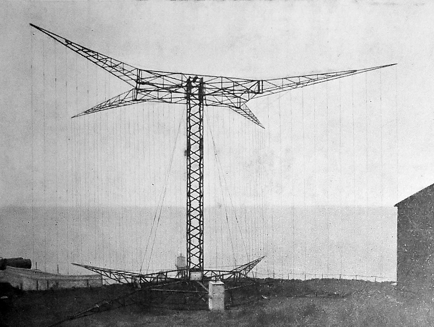
Experience shows that the beam transmitted by a projector of this nature
is not liable to distortion, and the method of signalling the
bearing is quite independent of the rate of rotation of the projector.
There is very little chance, therefore of error arising when using
this method of signalling wireless bearings.
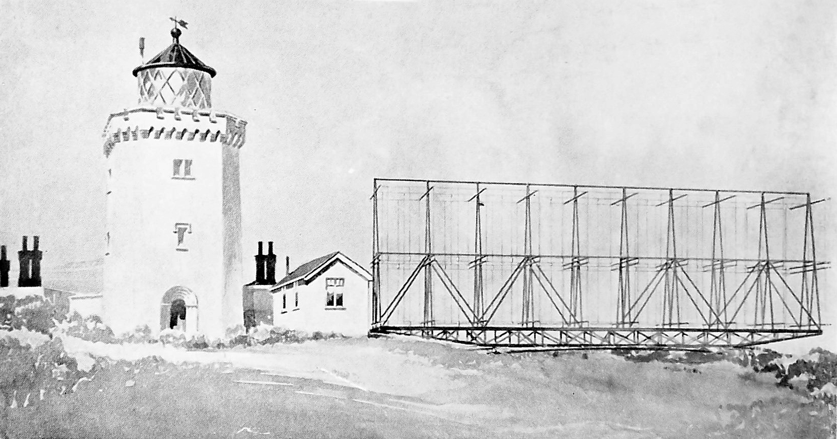
At this moment (circa 1923) there is one completed beam projector
operating on the Island of Inchkeith h in the Firth of Forth
and a second is being constructed close to the South Foreland Lighthouse.