 |
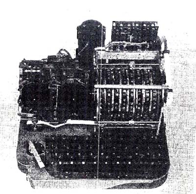
| This was a AFSAM-7/KL-7 prototype. A letter in the archives of the National Cryptologic Museum says [in part] "The AFSAM-7 was developed in the late 1940's...and went into production in 1952". (NSA photo) |
TSEC/KL-7 (ADONIS/POLLUX) GENERAL
The KL-7 was an off-line cipher machine, code name ADONIS, and was similar to, but more advanced than the famous German Enigma machine. It was a replacement for the SIGABA macine (ECM Mk II) and was based on a new cryptographic principle called "re-entry" which had been developed in mid-1940 by Albert W. Small and patented a year later. Re-entry, also known as "re-flexing" meant feeding the output of one step of a cryptographic system as input into another step and re-enciphering it.
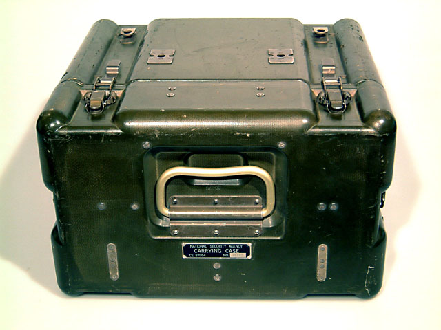
Initially starting with the designator AFSAM-7, it was renamed TSEC-KL7 in the early 1960's. KL-7 was used for the protection of exclusive (off-line) traffic. The unit had the approximate dimensions of a medium sized portable typewriter and was housed in an molded fiber glass carrying case which was painted in an olive drab, khaki colour. The dimensions of the carrying case were approximately 13.5 inches wide by 16.5 inches deep by 7 inches high. Navy versions, were of course, navy grey and the hinged case lid opened from front to rear. On the front of the KL7, there was a character counter to help keep track of the number of characters in a message and a small lamp to illuminate the keyboard. An excellent primer on how the ASAM-7 was developed and named can be found in this link.
|
| This was a AFSAM-7/KL-7 prototype. A letter in the archives of the National Cryptologic Museum says [in part] "The AFSAM-7 was developed in the late 1940's...and went into production in 1952". (NSA photo) |
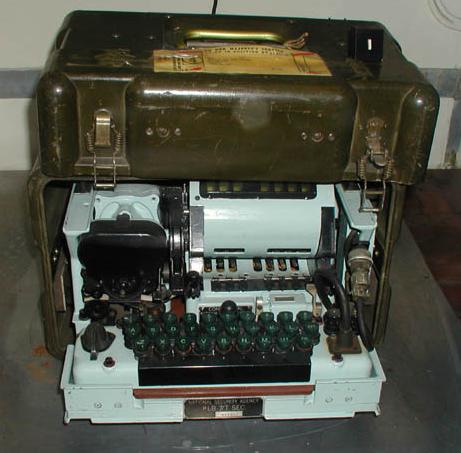
The KL-7 as displayed at the National Cryptologic Museum. (Photo by Jerry Proc) George Mace notes that "this is a very early and rare (KL-7) device with the nomenclature AFSAM-7 . AFSAM is the acronym for Armed Forces Security Agency
Machine. The predecessor of NSA, AFSA was established within the Department of Defense, under the command of the Joint Chiefs of Staff, on May 20, 1949.This machine had no DC power filter mounted on the right hand base frame since the power cord goes straight into the keyboard. It also has the old style screw-in, beveled-top fuse holders. The DC power input cord for all KL-7s screwed into a dummy connector mounted on the right hand side of the base unit for shipment.
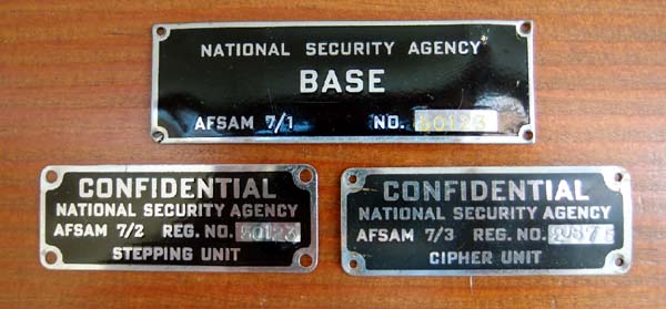
In the early 1960s, at the US Army Crypto Depot at Arlington Hall Station, Virginia, we changed hundreds of name plates to convert the AFSAM to TSEC nomenclature. I believe the base unit was AFSAM 7/1 (aka KLB), rotor stepping unit AFSAM 7/2 (aka KLA) and rotor basket AFSAM 7/3 (aka KLK). Instruction book TM 11-5810-215 Communications Security Equipment applied to the complete AFSAM-7".
This is the way the nameplates looked when the KL-7 was designated as AFSAM 7. Tag 7/1 is 3 inches wide by 1 inch tall. Tags 7/2 and 7/3 are 2.25 inches wide by 3/4 inch tall. (E-bay photo)
The KL-7 had eight rotors but the rotor in position #4 was stationery. As a result, there are seven windows on the rotor basket, one to view each rotor that moves. Counting from left to right, there is a wide black area between rotor #3 window and rotor #4 window. Behind this wide space is the actual #4 rotor, which does not move, hence there is no need to see it. All eight rotors provided electrical connections to encrypt/decrypt traffic. The drive pawls which caused the rotors to step were controlled by tiny magnets, which in turn were controlled by programmable notch rings, located on the seven moving rotors.In the July 1982 edition of Cryptologia there was an article titled "Helmich and the KL-7" by Deavours. Some extracts:
"The KL-7 is a classical type of wired rotor codewheel cryptograph. Early prototypes came into use in the late 1940's. The machine has an interesting history. After World War II the formation of NATO provided American and British cryptographers with quite a challenge: to provide secure cryptographic communications among the nations of the alliance while not yielding any vital cryptographic design secrets. Clearly, no cryptographic machine used by so many different parties could remain a secret from the Soviets for long. The KL-7 was a simple and elegant solution to this dilemma.
As is well known, the top American rotor machine of that day was the ECM (SIGABA), later modified to become the CCM, while that used by the British was the TYPEX. The ECM was the more secure of the two and was, in fact, considered too good to share since its use by foreign governments would render their communications secure from American and British codebreaking efforts. The KL-7, while not a direct copy of the TYPEX in any sense, did employ one of its cryptographic feature: interchangeable coding cylinders and rings. On the KL-7 system, plastic slip rings which controlled the rotor movements could be permuted among the coding cylinders to provide variations of rotor displacement. The KL-7 rotors had 36 contacts per rotor.
Attacks on the machine could be expected to involve high speed computations and precomputation - a task the Americans could accomplish and, to a lesser extent, the British. The machine thus produced a good grade of cipher security if used correctly while not really revealing any unknown principles and "tricks of the trade". The United States military also used the machine with each network having its own network keys and rotor wirings.
By 1963, the KL-7 was operationally obsolete. In fact, what KL-7 traffic was sent in United States installations was usually superenciphered on the KW-26, an on-line electronic machine."
One crypto expert did some additional research on the KL-7 and KL-47 machines. Here is what he found:
"First the types in order of development:1 AFSAM-7 = KL-7
2 AFSAM-47 = the troublemaker ( later in the text)
3 AFSAM-47B = KL-47First you have the KL-7, also referred to as ADONIS (US, UK, NATO) or POLLUX (UK, Canada). However ADONIS and POLLUX are actually not the names of the machines, but the names of the crypto principle (technically and procedures) they used for that machine. Before NSA, the KL-7 was named AFSAM-7 (AFSA Machine No 7), developed by the Armed Forces Security Agency (AFSA). This would become the new Combined Cipher Machine for use with the UK, Canada and NATO.
However, the US Navy decided to develop their own machine, not based on ADONIS or POLLUX, but on the BRUTUS principle. That one was however absolutely not compatible with the AFSAM-7 (later KL-7) and not as secure. They still insisted to develop that machine, and they called it the AFSAM-47.That AFSAM-47 was quite different from the AFSAM-7. It was based on the BRUTUS crypto principle, which used 26-pins rotors. However, the AFSAM-7 (later KL-7) used 36-pins rotors. Wheres the logic? There isnt any, apart from Army-Navy rivalry.
The US Navy eventually had to reverse course and redevelop the AFSAM-47 into the AFSAM-47B, which also applied the ADONIS principle with 36-pins rotors and fully compatible with the AFSAM-7. Hence the trouble with three machines, named AFSAM-7, AFSAM-47 (not compatible and obsolete) and AFSAM-47B
Once NSA was established, they finally decided to use a new nomenclature system and named the machines TSEC/KL-7 and TSEC/KL-47 (which is the compatible AFSAM-47B).
Now, what about the punctuation marks/uppercase system on the ? In the attached pdf document you find the uppercase systems used by machines types AFSAM-7 (KL-7)- and AFSAM-47 (KL-47). The AFSAM-47 (obsolete) used Extended Uppercase System with A-Z, 0-9, Space, LET, FIG, and - ( ) / : ? , . The AFSAM-7 (KL-7) used the Limited Uppercase System with A-Z, 0-9, SPACE, LET, FIG
In the attached document, referenced above, (see list at the bottom document) we see that the obsolete AFSAM-47 used A-Z, 0-9, SPACE, LET, FIG which are compatible, but it also used - ( ) / : ? , . and those are not compatible with the AFSAM-7 (KL-7).
The AFSAM-47B (your KL-47) is fully compatible with the KL-7. Therefore, the KL-47 at least took over the upper/lower case system A-Z, 0-9, SPACE, LET, FIG
It might be possible that the AFSAM-47B (your KL-47) also took over the - ( ) / : ? , . from the obsolete AFSAM-47, but I really doubt that, because if the KL-47 would use those punctuation, this would produce garbled text when received on a KL-7.
Conclusion: The KL-47 used A-Z, 0-9, SPACE, LET, FIG. "
SPECIFICATIONS
Description: A portable keyboard operated, tape-printing, electro-mechanical literal cipher machine which encrypts letter text and numerals but punctuation marks must be spelled out. Cryptographic variables are produced by an eight rotor, non-reciprocal permuting maze with an associated stepping mechanism. The rotors have 36 points and are provided with interchangeable and rotatable, notched rings
Keying Method: Rotors, keylist.
Input: Keyboard or optional HL-1 paper tape reader
Output: Printed, dry gummed, paper tape.
Speed: up to 60 wpm.
Weight: 20.5 lbs (machine only , less case)
Power Input: 115/230 VAC (50-60 Hz) with power convertor or 24 VDC vehicle battery
Power consumption: 60 watts
Dimensions: Height: 6 1/4 in; Width: 12 in; Depth: 12 in.Accessories: KLX-7 - a special input/output keyboard adapter used in conjunction with the HL-1 tape reader to provide semi-automatic encryption/decryption from a punched teletypewriter tape. The output of the KL-7 when used with these equipments remains the same and is printed out on unpunched gummed tape.
Applications: Off-line , strategic and tactical environments.
Introduced : 1953 [1]
Cost of production: $1,200 [1]
Units produced: Approximately 20,000 [1]
Approval: For unlimited service use (OPNAVINST 02651, 6 dated 14 May 1956
Publications: Maintenance - U.S. KAM-1, KAM-25, KAM-26,
NATO: AMSP 512, AMSP 518, AMSP 519
Operating - AMSP 507, KAO-41, KAO-11
Training: No specialized training was required for operators.Since the KL-7 machine had a high acoustical signature, there were concerns that it might be 'exploitable' therefore improvements were made in the KL7A. A higher degree of soundproofing was installed in order to counter the problems produced by the acoustics of the machine. Being designed and produced in the early 1950's, TEMPEST wasn't given much consideration because the main design goal was tactical use, just like the M-209.
TEMPEST is an unclassified term that describes the vulnerability of an electronic device to having the classified components of its design intercepted and exploited. A machine that does not process classified information does not have a TEMPEST problem, only a radio frequency interference problem. Acoustical signature describes those systems which make an audible sound (sonic or subsonic or ultrasonic) which is repetitive and identifiable to certain specific functions. If these sounds are recorded from a distance, it is potentially feasible to compromise the machine.
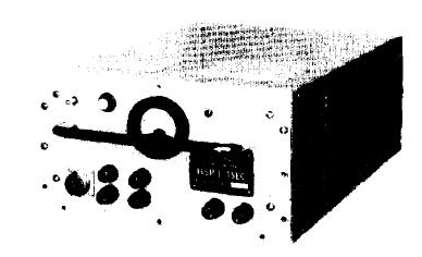 |
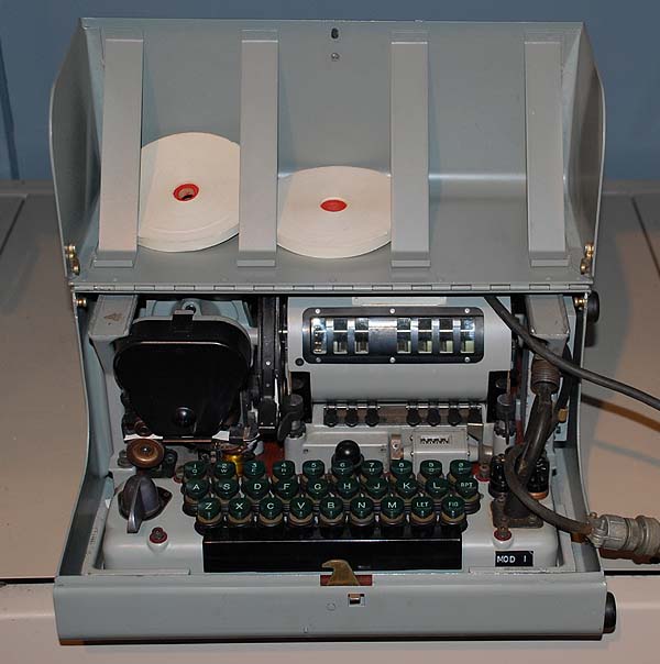
| This was captioned as a 'KL-7A' in an NSA document. What's inside the box and does it use an external keyboard? How does the operator replace the gummed paper tape? (NSA image) |
ROTOR INFORMATION
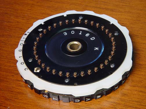
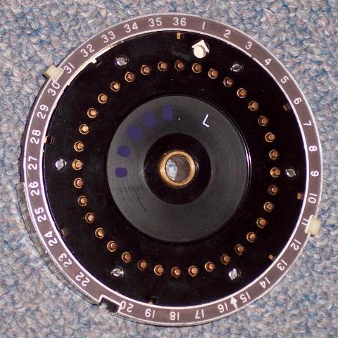
Close-up views of the left and right side of a KL-7 rotor. (Photos provided by David Hamer. National Cryptologic Museum/National Security Agency) The standard rotor box contained 12 rotors with letter designations of: A,B,C,D,E,F,G,H,I,J,K,L
but the L-rotor was noticeably different than the others. It was designed for use in position #4, the stationery position. Position #4 is the only one on the rotor basket which does not have window.
The 'L' rotor was fitted with two white TABS on the circumference of the rotor at positions #30-31 and #11. It could only be used in position 4, the stationery position of the KLK rotor shell. These TABS fit into milled slots in the KLK basket. The number 4 rotor also does not have notches around it's circumference for the drive pawls to activate or latch pawls to lock into. The rotor has 36 contacts on one side which exit on 36 contacts on the other side. (Photo by Richard Brisson) The alphabet on the rotors is grouped into clusters of three letters and two letters with spaces between the clusters and in the sequence: AB CDE FG HIJ KLM NO PQR ST UVW XYZ . Twenty six letters plus 10 spaces between letter clusters is equal to 36 contacts on the rotor. Can anyone explain this non-contiguous letter arrangement? One opinion says "This was the easiest and most apparent way to insert the 10 extra contacts needed for equal spacing. These 10 contacts formed the (reflector) reentry circuits through the rotor maze and are the only reason a rotor had 36 contacts!"
There are two serial number formats used on the rotors. Both have a five character serial number. One format has 4 digits and a letter while the other format has three slightly separated subgroups (2 letters, letter-digit, digit). The serial number format changed around 1975 when the M-rotor was introduced. This extra rotor was rewired monthly (at least in Denmark).
The operational L-rotor was anything but straight through rotor. In Denmark it was sent to AMSA (Allied Military Security Agency) once a year for rewiring and it was strictly forbidden to open this rotor. The remaining rotors were rewired on a yearly basis at NAMSA (NATO Maintenance and Supply Agency) , though one rotor, the M-rotor, was rewired monthly at the crypto center.
Maintenance rotors were classified as CONFIDENTIAL. The KL-7 was also cleared to process "Top Secret for Commanders Eyes Only".
The KL-7 was notorious for rotor and also keyboard contact problems. It was so problematic for the Germany army that they build their own option (EZ-KL7)as a workaround. KL-7 operators were expected to clean the contacts regularly with a gum pencil eraser - daily, if not more often. High traffic volumes led to a tendency to try and "cheat" and get more traffic processed before cleaning the contacts. This resulted in many problems.
There is one anecdotal story about KL-7 contact reliability problems. "In this instance 12 or 14 of us put our signatures on the TOP SECRET cover sheet before we handed the commander his "FOR COMMANDER'S EYES ONLY" message. We were working the same message on three different machines and suspected on reflection, that dirty contacts may have contributed greatly to our problem."
RELIABILITY
Dirk Rijmenants writes:
"Despite its extensive use, the KL-7 wasn't the most popular machine. On start-up, the vacuum tubes need 16 seconds to heat up before you can type on its keyboard, as the printer timing is controlled by the electronics. The KL-7 also has a high acoustical signature, and the motor gears produces a high-pitched noise. The KL-7 was notorious for its keyboard and rotor contact problems. The operator often had to push firmly on the keys to get the machine cycling, not allowing him to get any speed. Dirty contacts could cause the machine to halt, the so-called dead-rove.
To avoid such contact problems, the rotors and keyboard contacts had to be cleaned regularly and meticulously. The reason for these regular contact problems is the use of rotors and the sliding contact board. From any key to printing, there are two contact points in Plain mode. In Encipher or Decipher mode, there are 13 contact points, and two additional contact points when the FIG or LET key is used. Moreover, each pass through the re-entry wires can add another 9 contact points. In total, 472 contacts must work flawlessly to prevent the notorious dead-rove".
 |
| A complete KL-7 rotor set. (Photo via Jan Lispet) |
 |
| This rotor set is held by the National Cryptologic Museum. (Photo by Ralph Simpson) |
This a good view of the disassembled rotor basket. (Courtesy Eric Morgan, History of Communications Security in New Zealand)
This view shows the contact shoe arrangement for the rotor assembly. There are no rotors installed. (Photo by Jerry Proc)
 |
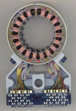
| Contact side of the stator. The stator bracketed each end of the rotor basket and made contact with the rotor wiring maze.. (Provided by George Mace. Photo by Jerry Proc) |
 |
| Wired side of the stator. (Provided by George Mace. Photo by Jerry Proc) |
OPERATING THE KL-7In the Royal Canadian Navy, a complete second rotor assembly was stored in a separate box away from the machine. This assembly had the settings from the previous day and could easily be substituted into the KL-7 to decode a late arriving message from the previous day. To encrypt a plain text message, the operator would enter the message on the keyboard and the KL7 generated a gummed tape using 5 letter groups. This tape was supplied in either 3/16" or 1/4" wide rolls about two inches in diameter. The tape was pasted on a message pad and the resultant encoded message was submitted to a ship's Message Centre where specific information such as Routing Indicators and Date-Time-Group was added. Finally, the complete message was passed to a radio operator or a Teletype operator for transmission. To decrypt, coded messages were received in 5 letter groups. These, in turn, would be entered on the KL-7 keyboard, and the machine would generate a gummed tape with the plain language text on it. This was pasted on a message pad and given to the Message Centre where it was typed up and duplicated for distribution within the ship and for filing. According to Walt Hutchens, an ex-USN coder, "the noise produced by the KL-7 rotors advancing was one of the two most distinctive sounds that I have ever heard. The other sound was the last round and the clip being ejected from an M-1 Garand".
An ex-army communicator who operated a KL-7 for 10 years, relates his impressions of the machine. "Rotors had to be taken out of the machine, cleaned and lubricated at periodic intervals. A special oil would be applied then wiped off the rotor contacts. For each keystroke, the machine made a 'plunking' sound. An operator could not achieve any speed on the machine because one had to press very hard on the keys to get the machine to cycle. In the encode mode, the KL-7 would add a space after each five letters. The advanced design of the machine also permitted the encoding of the space character, numeric characters but punctuation had to be spelled out in full.
After a message was decoded, the operator first had to read the security level classification of the document. If the operator was not cleared to the correct level, he was required to stop and locate another person with sufficient clearance. In the Comm Center itself, there was a list of personnel who were cleared to be in area. No one else was allowed. Once a general had to be informed that he could not be granted access because his name was not on the list. He did not push it at the time but the next day a revised list was received from Ottawa with his name on it".
Bill Moffatt (LSCV1, RCN 1950-1955) served in HMCS Iroquois in Korea in 1952. That ship was fitted with a KL-7, a Typex and a one-time pad. That means the KL-7 was already in service by 1952. Bill goes on to say "The main use for the KL-7 in Korea was to decrypt messages from the American forces which were situation summaries and position reports of enemy forces put together by the Americans from reports from observation posts or friendly agents behind the enemy lines. We considered most of them a waste of our time".
Mike Simpson, a former operator relates this piece of information. "One problem we had with the KL-7 was the sticky tape the 5-letter code groups were typed on during encryption, or the plain text during decryption. If the weather got very cold, the glue became very brittle thus causing the paper to break".
Components for the KL-7 and its variants were manufactured in the mid 50's to the mid 60's by several United States government contracted firms and the Singer Company was a major supplier. The parts were then assembled at either the Philadelphia Army Depot or at the Bluegrass, Kentucky plant. After final assembly, the units became the property of the National Security Agency and were distributed to the various military users. All crypto machines and materials were on loan to North Atlantic Treaty Organization member countries including Canada. In addition, there was also an airborne version of the KL-7 which was modified at one of the US Air Force Security Service facilities in Mississippi for use in aircraft.
Technicians maintaining the KL-7's held high level security clearances but were not allowed to troubleshoot rotors point-to-point or to search for "roving deads." Testing rotors from side to side was forbidden. They had no need to know how rotors were wired. Continuity was checked by placing the rotor on a conductive surface connected to one probe of an ohmmeter. The tech then moved the other probe from one contact to the other until all paths were tested. Defective rotors were returned to NSA for repair or disposal.
Operators could also identify roving deads. With the KL-7 in the encipher and then decipher positions, an operator could depress the L key and repeat function key and allow the machine to cycle several hundred times. If the machine stopped cycling under these conditions it indicated an open circuit in one of the rotors or dirty contact between the KLK rotor basket end plates and circuit board.
After the Walker family spy ring was exposed in the mid-1980's, it was found that they had supplied the Soviet Union with a complete working KL-7 and all keying materials. Immediately, all KL-7's were withdrawn from service and returned to the COMSEC depot at Ft. Mead Maryland. This included all code books, spare parts, manuals and any other paraphernalia associated with the unit. The system had been in service with the Royal Canadian Navy for 27 years.
All of the crypto gear fitted on Canadian ships in the 1950's and 1960's was owned by the National Security Agency of the United States and was loaned to North Atlantic Treaty Organization member countries including Canada. Also included, was keying material, key lists, certain rotors, and key cards. This material came in a variety of editions depending upon the application. Examples of these crypto packages would be named CANUSEYESONLY, CANUKUS, AUSCANUKUS, NATO, ALLIED, and so on. Some of it was CANEYESONLY and would have been generated in Canada by the Communications Security Establishment. The United States used NOFORN (Not For Foreign Dissemination). It was even used in combination with UNCLAS as in UNCLAS NOFORN, or, to be more likely, UNCLAS E F T O NOFORN (EFTO means Encrypt For Transmission Only).
| History of the KL7 by Dirk Rijmenants |
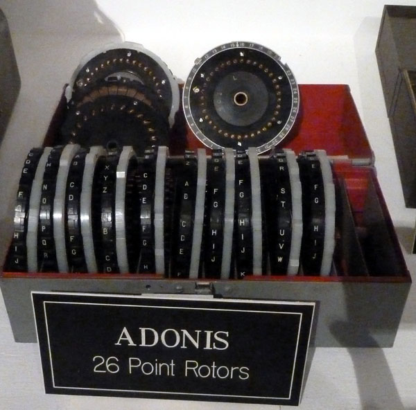
THE PALLAS KEY SQUARESam Stokes spent a few years in the U.S. Naval Security Group, and had occasion to use the Adonis when he was in Alaska. He provides an explanation for the use of the Pallas Key Square when setting up the encryption and decryption for the KL-7.
"First, the rotors had to be assembled and set for a particular day according to a key list that was kept in the safe. The rotor sets were kept in a box and were assembled in the rotor basket in a particular sequence for each day. In addition, each rotor had a rotating ring that was set in a particular position for each day.
Besides the daily rotor settings, in order for the message to be decrypted, the operator had to know how to initially position the rotors for each message, so the first step in encrypting a message was to select a set of randomly generated numbers from a book that both operators kept in a safe.
Those numbers were then run through an operating aid called the Pallas Key Square. It was a very large piece of paper (that folded up like a road map) and contained a bunch of very confusing rows and columns of numbers with letters and numbers along the edges of each row and column. The random number settings from the book were run through the key square to be "encrypted." As I recall, the numbers were run through the columns and rows according to the date and I think each key square was good for a month.
It was very easy to be off a row or column and screw it up so that the other end had bad numbers and wouldn't be able to decrypt the message. My memory has gone south on me here, but I think you had to do this for each rotor, so you had to run the numbers though the key square eight times, one for each rotor. As I recall, the Pallas Key Square was not highly classified; I think it was Confidential, even though we were sending traffic of a much higher classification
The resulting letters and numbers were put into a five letter code group in the message header, I believe, right after the date-time-group. The operator at the other end would set up his rotors for whatever day it was, and then take out his Pallas Key Square and run the numbers from the message header so he would know how to set up his rotors to begin to decrypt the message.
The machine I used was manufactured by the Teletype Corp. and had a green button by each rotor position. The green button was used to step each rotor into the proper position. Our procedure was to have two people do this. Each person had to pass the Crypto Board Test in order to be qualified to operate the Adonis KL-7, off-line machine.
One would encrypt the message and the other would decrypt the message before it was sent out for actual transmission. We had two KL-7's in order to do this.
As I recall, were supposed to actually set up the rotors in each machine before testing the message. Since it was a big hassle to open up the basket, get the rotors out of the safe, and assemble the eight rotors in the correct position for the day, in actual practice, we just took the rotor basket out of the machine used to encrypt the message and put it in the second machine and try to decrypt the message.Now that I think about it years later, this might also explain why the distant end couldn't decrypt several of our messages.
Also, the rules said that each time the crypto vault was opened; the entire contents had to be inventoried. We had a walk-in vault that contained several months of keying materials as well as superseded material. It took about an hour to properly inventory everything, so we tried to open the vault as few times as possible.
Why was I using a KL-7 when we had a circuit with on-line synchronous crypto gear? We used it because we had a vessel snooping around in the Arctic (not the Canadian Arctic) and had to communicate with this vessel through the Navy General Service communications system, rather than our own Naval Security Group circuits, so the messages were off-line encoded and sent via the regular message center.
After I was in Alaska, I went to Guam for 18 months, and although I was certified on the KL-7 while on Guam, I never had the opportunity to use it. In 1968, the KL-7 was a very old system.
I did see it being used when I was a Tech Controller in San Diego. The USS Pueblo crew was being debriefed at the Balboa Naval Hospital, and we set up special circuits from the hospital for this operation, but also sent traffic via the General Service System. Once again, NSG messages being sent via the GENSER system were first encrypted using the Adonis system.
Disclaimer: This was a few years ago, so I may be incorrect in some of the details, but I think I got the major stuff right".
Sam Stokes, KG6WYZ, is now in the publishing business.
ALTERNATE SYSTEM NAME
Maurice Cammack says the KL-7 had two system names. He expands on this. "The KL-7 was known by two system names. ADONIS and POLLUX were associated with the type of cryptographic operations being performed by the device. ADONIS would be used by higher level units. POLLUX would use common rotors for inter-service communications between the Army and Air Force. Both services placed conditions on the Pollox option but eventually adopted it.
When used as an "Adonis" device, each message encrypted with the KL-7 also included an encrypted message indicator, or the initial alignment of the rotors for encryption/decryption purposes. The KL-7 was set up for each day's key according to a keylist distributed by NSA, or the various military cryptologic agencies. In addition, a gummed roll of random five letter indicators was distributed along with the keylist.
To encrypt a message, the next gummed letter combination was torn off, and pasted to the log sheet which contained details about the message, i. e., originator, addressee, date time group, precedence, etc. This was to ensure that the gummed message indicator was not reused. The encrypting operator, using the initial days setting on the device, encrypted the gummed tape random five letter group, and used the resulting encrypted output to align the rotors again before actually typing in the message contents. When the message was transmitted, the ORIGINAL random five letter combination, torn from the gummed roll, was sent as the first five groups, each letter being spelled out phonetically. R for example was spelled as Romeo, etc. The receiving operator would set up the days key, associated with the date time group of the message, and encrypt the message indicator received as the first five groups of the message. The output from this operation was then used to align the rotors, the machine was switched to decipher mode, and the five letter coded groups were typed into the device, with the clear text coming out on gummed tape. The clear text was then pasted on a sheet of paper, and unless it was an "Eyes Only" type message, passed onto a clerk who would type the message on a mill typewriter.
The primary difference between Adonis and Pollux was the message indicator. When used as a Pollux encryption device, the message indicator was not encrypted, but passed phonetically in the clear as the first five groups in the message. The receiving operator used these five groups to align his rotors, switched to decipher and typed in the encoded groups, with clear text being printed on gummed tape. From this, anyone can see the obvious insecurity associated with the Pollux system and recognize that the Adonis system's use of encrypted message indicators was an attempt to increase the security of the information encrypted in the KL-7 hardware system.
The gummed indicators, sent in a roll by the cryptologic agencies, was also an attempt to ensure the selection of more random message indicators. Early on, operators simply set up the rotors, switched to encipher and held down random keys to generate a string of message indicators which were used to encipher individual messages. In the Spring of 1957, I was sent, along with several of my fellow cryptographers, to assist the newly formed German Army Signal Corps' NATO elements in using the KL-7 during field exercises. We were carefully instructed to show them how to use the Pollux KL-7 system only, and could not discuss the use of the machine with encrypted message indicators (Adonis). One of our objectives was to ensure that the German Cryptographers used a random message indicator for each message, and we showed them how to create a string of message indicators like I mentioned above. Within a day or so, the German cryptographers, many of whom were former members of the Nazi Army Signal Corps, were making up their own message indicators from memory, and some of them used the same indicator over and over, which further reduced the security of the Pollux system. It was not until the senior Signal Officer at the Headquarters in Mainz convened a meeting of all of the German cryptographers and explained the rules, as only an old German Army Officer could, that the message indicator selection problems were corrected.
One humorous aside to my time with the German cryptographers - they constantly tried to get me to describe other cryptographic systems that we had in the American Army because they knew we couldn't possibly trust our secret communications to a piece of junk like the KL-7".
THEORY OF OPERATION
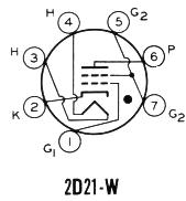
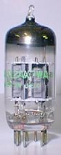
The KL-7 used three type 2D21 and one 12AX7 vacuum tubes. There was one spare of each type plugged into the circuit board. Crypto-variables such as rotor settings were referenced from a hard bound paper code book or 'flash' paper bound into a small booklet.
George Mace provides a brief description on how the KL-7 prints characters. "Depressing any keyboard letters/ figures key would place a ground on its associated coil, located in the printer unit. These coils were arranged in a 360-degree pattern, in two rings. A magnetic rotor spinning at 2200 RPM would then induce a small analog signal into a transformer. All the analog signals were the same, except for their timing based on their angular position in the two rings. The transformer output analog signal was applied to one grid of the 2D21 Print tube and also triggered the 12AX7 Gate tube.
This Gate Tube output was applied to the second grid of the Print tube and controlled the timing, thus printing the correct character. All that the encipher or decipher switch on the keyboard did was place the rotor basket contacts in series with the key paths before their connection to the printer coils. The sliding contact board actually performed this function by routing any letters/figures key ground straight to the printer coils in the "Plain" position and to the left or right hand rotor basket contacts in the Encipher or Decipher position. When conducting, the 2D21 Shift tube provided a time delay via the 12AX7 gate tube allowing a figures character to print instead of the letter since both used the same keyboard key.
The "notch" in the upper left hand corner of the sliding contact board facing the printer unit was actually a cam. In the encipher position, it pushed a pin forward into the printer tape feed mechanism and produced the "space" between the 5 letter code groups. There were 4 cam-operated switches located under the printer unit motor that operated with every cycle. These removed the plate voltages from the various 2D21 tubes, since these were gas tube switches and could not be shut off by grid voltage.
Note: If an incorrect letter was typed during Encipher or Decypher the KL-7 did NOT lose crypto key synchronization; it only produced one incorrect letter! The rotors would step once or remain stationary each cycle depending on their notch cams regardless of which letter key was typed.
Descriptions of the KL7 subassemblies:
1. The KLB-7/TSEC was the device base unit consisting of the aluminum frame, circuit board, printer
unit and keyboard. The plastic bubble on center behind the keyboard was the shift lamp, indicating upper or lower case figures.2. The KLK-7 was the rotor basket, holding eight rotors. Number four rotor was stationary, while the other seven could rotate. Each side of the rotor basket has two groups of 26 contacts and 10 contacts. The 26 contacts make connection to the circuit board and then onto the keyboard. The 10 contacts however make contact only with the KLA Stepping unit where an internal wiring harness routed the signal path back to the 10 contacts on the other side. This was called the reentry circuit (reflector) for a more secure system.
3. The KLA-7 was the rotor stepping unit containing 7 magnets and 7 switch assemblies, to determine the rotor stepping pattern. The printer unit provided mechanical power to the stepping unit by a drive arm.
4. The KLX-7 was the keyboard adapter with wiring harness to allow interconnection to the TSEC/HL-1 Baudot paper tape reader. The HL-1 could only read tapes, it could not punch tapes.
5. PRINTER - The printer had a print wheel spinning at 2200 RPM and characters were picked off on the fly and printed onto the paper tape. This print wheel did not stop as it did on the ECM SIGABA machine!
6) POWER SUPPLY - The KL-7 was one of the first COMSEC devices to use germanium diodes for full wave rectification of the A/C generator (400 cycles?) located in the printer unit. This produced the 200 and 220 volt DC power supplies for the electron tube plate voltages. Also a negative 72 volt power supply was provided for the electron tube grid bias.
In it's heyday the KL-7 was was considered to be an electro-mechanical "giant" in spite of its small size.
POWER AND TAPE READER INPUT
POWER
When used with a 24 DC power source, one end of the DC power cable connects with the DC power source such as batteries. The other has a round connector which attaches to the right hand side of the KL-7 keyboard to the DC input connector. DC then passes through the two fuses, and then through the sliding permuter board to power the KL-7.
When the 120 VAC to 24 VDC power converter is used, the DC cable would plug into the DC power connector.
TAPE READER
The KL-7 could also be used with the TSEC/HL-1 Baudot paper tape reader. To make the connection,
the KL-7 key board was removed and the KLX-7 keyboard adapter inserted, with the sliding permuter board under it and then the keyboard was reinstalled. On the front edge of the KLX-7 there was a small rectangular connector which accepted the cable input from the HL-1. The keyboard remained fully functional with the KLX-7 installed but it just sat a little higher.KL-7 MODIFICATIONS AND IMPROVEMENTS
1) KLK rotor basket: The original end covers were made of plastic which cracked. They were replaced with black anodized aluminum covers.
2) KLB Keyboard: Two arms from the space function bar entered the keyboard housing and were protected from dirt/dust entry by four rubber pieces glued inside the keyboard. The original rubbers
contained chemicals (possibly sulfur) that tarnished the silver plated contacts on the sliding board with a heavy black coating. After new composition rubbers were installed, the keyboard contacts were cleaned to solve the problem.3) KLA Rotor Stepping Unit: The original shaft used to drive the rotor step pawls had case hardened plates to push against the pawls. This shaft was replaced with a unit that had seven roller bearings
to drive the pawls and required less mechanical power from the printer motor.4) KLB Keyboard: The two original fuse holders on the right hand side of the keyboard were screw in cap type. They were replaced with twist lock cap type fuse holders.
5) KLB Printer Unit: The original motor speed was maintained at 2200 RPM's by a thermistor type unit on the rear of the motor and not very effective. The entire motor was replaced with a self-contained, mechanical contact-governor unit that was very effective.
6) KLB Circuit Board: The original germanium diodes were dark brown and of octagonal shaped construction. Newer boards and replacement diodes were lighter brown and cylindrical in construction.
7) KLB Circuit Board: The original plunger-type male contacts were solid pins and were prone to bend easily. Newer boards and replacement contacts were of heavy-duty construction.
8) EZ-KL7 - An option specific to the German Army. See photo below for explanation.
The KLX-7 option is shown installed under the keyboard with its front facing connector. This machine example has an additional option which was added to meet the requirements of the Bundeswehr, the German army.
Klaus Kopacz explains "The KL-7 in the picture is the KL-7 tandem version. The German army constructed a supplementary device named EZ-KL7 to solve the electrical contact problems encountered in the KL-7. This device was used to operate two KL-7 machines in tandem in order to detect encryption and decryption errors. The first KL-7 encrypted and the second one decrypted the result or vice versa. The task of the EZ-KL7 was to compare the results.
To use the KL-7 in this manner, some redesign was necessary. The assembly fitted to the front and below the keyboard is the control module only. Behind the rotor basket is the connector box which interfaced with the EZ-KL7 option. The EZ-KL7 was only used by the Bundeswehr but was offered to other NATO member countries. The offer was declined since many members preferred to migrate to more modern machines like the KW-7". (Photo source: Die Welt der geheimen Zeichen book)
 |
| This is the example of the KL-7 aboard HMS Belfast. (Photo by David Hamer) |
 |
| These superb photos of the KL-7 assembly (above) and the AC power converter (below) were supplied by John Alexander, G7GCK Leicester, England. The KL-7 is shown in the "sanitized" condition with rotors missing and identification plates rendered illegible. The top photo shows the power cord connecting to the filter and then to the keyboard. (Photo and copy courtesy John Alexander, G7GCK Leicester, UK). |
 |
|
|
 |
| This view of the KL-7 accessory rack shows the placement of the AC power converter and spares case. The US Army issued this accessory rack with every KL-7 since it contained the AC power converter. (Photo courtesy John Alexander, G7GCK Leicester, UK) |
 |
| This view illustrates some of the details on the inside of the lid. (Photo via Jan Lispet) |
 |
| KL-7 shipping and carrying case. (Photo via Jan Lispet) |
 |
| KL-7 in metal desk case. This example is held by the C&E Museum Kingston, Ont. Two full reels of gummed paper tape have been placed in the lid to show their relative size. The KL-7 remained in production from 1952 to 1968.(Photo by Jerry Proc) |
 |
| With lid closed. (Photo by Jerry Proc) |
MAINTENANCE SECTIONTOOLS AND ACCESSORIES
This graphic is a simulation of a KL-7 butterfly rotor tool. It was used to adjust the KLA-7 rotor stepping unit. The tool was made of machined steel, about 1/4 inch thick and rotated on a steel shaft, just like the rotors. One side of the butterfly had a high and low cam surface which was used to adjust the stepping switches. The other side of the butterfly (the side facing outwards in the photo) had a given space to adjust the rotor drive pawls and rotor stops so a rotor would step only once per machine cycle. This tool was used with the KLA-7 removed from the KLB-7 base. (Illustration and copy via George Mace <gmace8(at)comcast.net>)
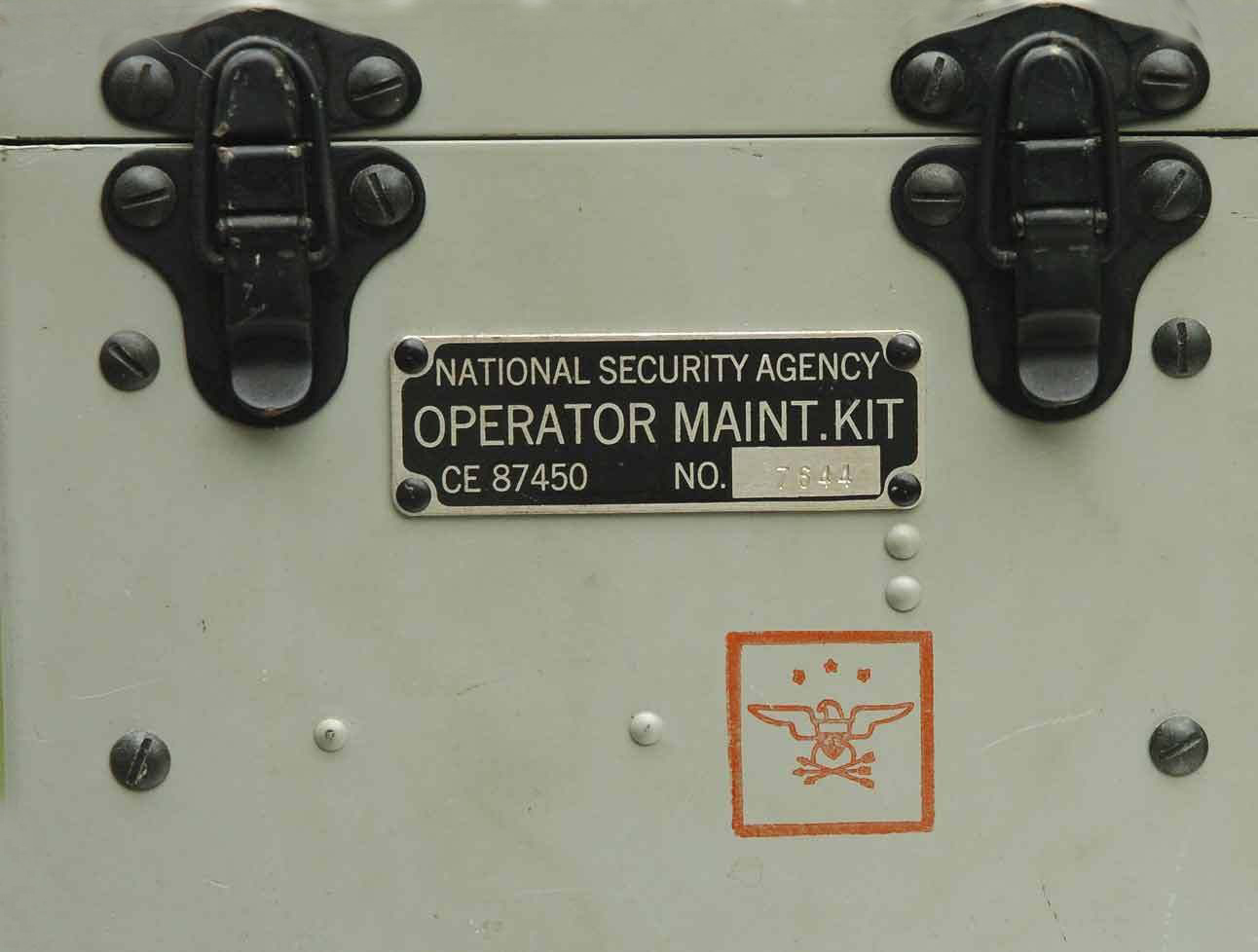
The KL-7 maintenance kit (# CE 87450) includes the following items: - Contact eraser. Parapink AW
Faber-Castell #701
- Finger mount tape cutter.
- Two different size tube pullers.
- Four 2D21W boxed tubes.
- Dust brush.
- Bristle "tooth brush"
- Contact burnisher block and spare cloth strip.
- New package of lint free cloths #CE87298
- One General Electric NE-48 bulb for the "Shift" lamp.
- One W313 bulb for the "Keyboard Illumination" lamp.
- One gum tape moistener.
- Pin straighteners (red and blue) for 7 and 9 pin tubes.
- Missing is metal can of red colored cleaner/lubricant (Quietone ?)The box itself measures 6 in. x 6 in. x 5.5 in.
(Photo via e-bay. Copy by George Mace).
 |
| KL-7 paper tape moistener . It was made by the Teletype Corporation (Photo by Darwin Maning) |
External view of above KL-7 maintenance kit p/n CE 87450. (E-bay photo)
Another version of the KL-7 maintenance kit. This type was provided by NATO and used for several years in The Netherlands. Clearly visible on the light blue booklet is the word Landmacht which translates to "Army" or "Armed Forces". (Photo via Jan Lispet)
PARTS AND SUB-COMPONENTS2D21 THYRATRON CHARACTERISTICS
- Type: 7 pin, miniature gas tetrode
- Filament: 6.3 VAC @0.6 amps
- Peak Forward Voltage: 650 volts
- Peak Reverse Voltage: 1350 volts
- Peak Plate Current: 500 ma
- Average Plate Current: 100 ma
- First introduced: 1944
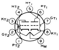
12AX7 CHARACTERISTICS
Type: 9 pin miniature; high-mu triode
Filament 12.6V (series); 6.3 V (parallel)
0.15 amps (series); .0.3 amps (parallel)
Plate Voltage: 330 V max /100 V typical
Plate Current: 1.2 ma max/ 0.5 ma typical
Plate Dissipation: 1 watt per section
First introduced: 1947
This is the contact side of the double-sided permutor which sat beneath the KL-7 keyboard. The material is linen phenolic and the thickness is about 0.2". It has been milled out to accept pressed-in silver contacts. The surfaces are quite smooth, as if they were surface ground after the contacts were installed. The rollers and tracks have enough latitude to allow a linear travel of about 3/4". This is the roller side of the double-sided permutor .This piece lives under the KL-7 keyboard and somehow interconnects the keyboard switches (above the keyboard contact assembly) with other KL-7 contacts below the keyboard contact assembly. This keyboard contact assembly can move from left to right and the rollers which support it allow it to move about 3/4" total. Photos and copy in this this table by David Ross N7EPI
Shipping boxes containing crypto machine spare parts were stamped with the red American eagle. (Photo courtesy George Mace). The origins of the red eagle stamp are not clear at this time. One source believes it was used at the Lexington Signals Depot Rehab Facility or by DECAS (Defense Contractors Acceptance System) and would have been an acceptance or repaired/modified acceptance stamp. Can anyone confirm?
A close-up of the printer assembly. The plain text output was printed on a dry-gummed paper tape. (Photo by Jerry Proc)
KL-7 printer clutch components. (Image by George Mace) KL-7 paper tape canister. (Image by George Mace)
Contact plate assembly with cover off. (Image by George Mace) Close-up of contact plate wiring. (Image by George Mace)
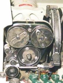
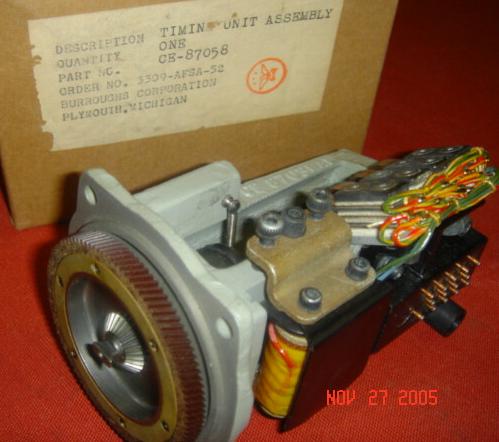
KL-7 TIMING UNIT: THE HEART OF THE MACHINE The shipping box states Timing Unit Assembly, CE-87058, Burroughs
Corp, Plymouth Michigan which definitely identifies it as KL-7. It also states Order No. 3309-AFSA-52, which identifies the Armed Forces Security Agency 1952. The timing unit is located under the printer unit motor. (E-Bay photo)The white plastic cam upon which the four switch "arms" ride is
actually four cams molded so that each switch operates in a
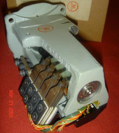
predetermined sequence. The purpose of the cam is to interrupt the B+ supply to each of the 2D21 gas tubes thus shutting them off. (E-Bay photo)Fourteen pressure contacts are shown here. These are the initial version of the contacts which bent easily but were later replaced with heavy duty contacts. Three contacts for each switch assembly (12) and two for the clutch solenoid. (E-Bay photo) The large fiber gear was constantly turning when the motor was
running. Letters and figures were picked off the print wheel "on the
fly" at 2200 RPM. Energizing the clutch solenoid would allow the machine to cycle once. The small beveled gear in the center meshed with a bellcrank gear that stepped the rotor assembly once. The "offset" machined protrusion in the center of the beveled gear "keyed" into a mating shaft which drove the paper tape advance assembly. This
offset was necessary or else you could get the tape feed 180 degrees
out of phase! (E-Bay photo)
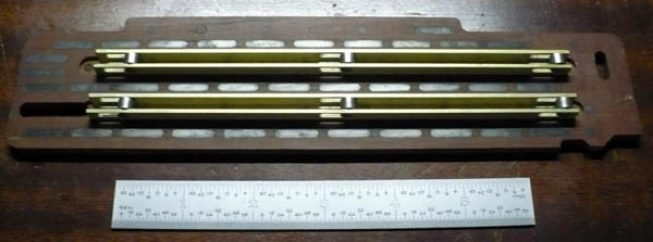
KLA-7 ROTOR STEPPING SWITCHES These are the rotor stepping switches (less wiring harness) used in the KL-7. Without the wiring harness, this assembly was unclassified. The white-notched rings in the rotors would actuate these switches and determine which rotors would step on the next machine cycle. (Photo and copy via George Mace)
MOTOR/INVERTER This is the DC motor/inverter which provided all of the mechanical and internal electrical power for the KL-7. It's an early type which employed a thermistor speed control . Nameplate data reads: Inverter Type MG-27 (B); S/N: E-2791. Input 24 volts D.C. 1 Amp. D.C. Output: 1 Phase; 6000 R.P.M.; 440 cycles; 200 Volts peak. 0.015 int. hp. Manufactured by the Red Bank Division, Bendix Aviation Corporation, Red Bank, New Jersey. This unit is also stamped M.F.P. OCT 1953. It has four spring loaded pins labeled N1 thru N4. Weight is 2 pounds 6.4 oz unboxed. The small gear has 20 teeth and is approximately 0.5 inch in diameter. (Photos via E-bay)
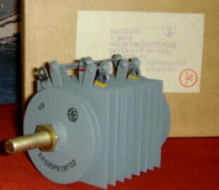
Power supply selenium rectifier. This was one of two types. (Photo courtesy E-bay) Type K9
The heavy duty, full wave selenium rectifier pictured above, was one of two used in the KL-7 A.C. power converter. This power converter contained a step-down transformer with a rectifier mounted on each side of it. Threaded studs in the center of the rectifiers were used to secure the power converter metal cover.
The full wave selenium rectifier is stamped General Electric Part Number 6RS25PB1BFD2 along with the GE logo, K-9, the United States Government National Stock Number, (NSN) 6130-00-980-0599. The shipping box identifies it as a 1959 procurement. This is the info from the box label: CE-11970, 1 each, Selenium Rectifier, DA-18-119-SC-654; 211-LYN-59; Burroughs Corp, Plymouth , Michigan. It also has the Burroughs Quality Control stamp 12-B-500 in a circle, and that ever famous, red EAGLE in a red circle with outstretched wings. Electrical ratings as taken from the FEDLOG DATA are : 45 VOLTS AC rms max; D.C. Output is 35 V at 2.4 amps into a resistive load.
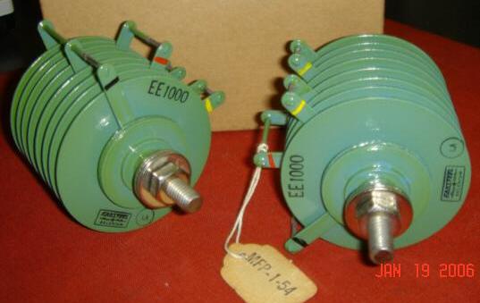
Type EE-1000
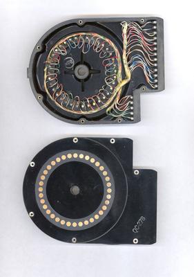
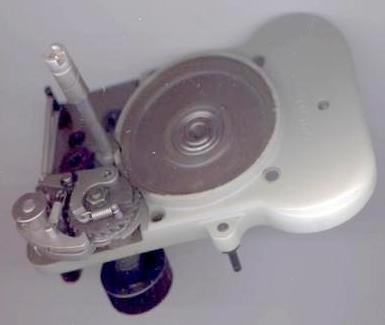
Full Wave Selenium Rectifiers, Type EE-1000. Ratings: 45 VAC rms, Max D.C. output is 35 V at 2.4 Amperes into a Resistive Load. The tag which is stamped MFP-1-54 indicates that these parts were Moisture Fungus Proofed in January 1954. The parts box shows a 1949 procurement number and the label on the box reads: CE-11970, 2 EACH, SELENIUM RECTIFIER, DA-49-170-SC-1332-2A; BURROUGHS CORPORATION, PLYMOUTH, MICHIGAN. (Photo via E-bay) PULSE GENERATOR - ASSEMBLED AND DISASSEMBLED VIEWS
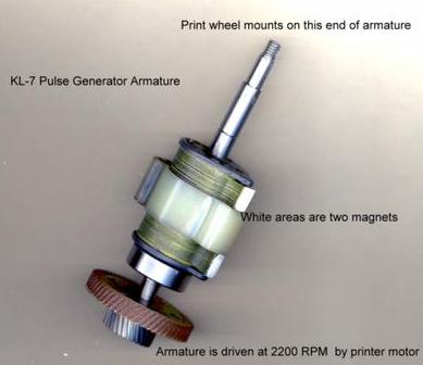
The pulse generator contains all the coils for printing and the spinning magnet which induces the analog signal. It also has the spacing assembly which generated the five letter code groups.
There are 30 contacts for this unit. The first 26 are labelled A through Z and the last four are numbered 1 through 4. Inside, however, there are 37 pulse coils. They are arranged as follows:
26 coils for the letters of the alphabet A through Z; 10 coils for the figures 1 through 0; and one for a SPACE function. Pulse coils for the top row of letter/figures keys are wired in series and produce two analog signals by the spinning magnets.
Markings: PULSE GENERATOR ASSEMBLY; PN: CE-87056; ORDER NO. 3309-AFSA-52. "AFSA" Armed Forces Security Agency. Manufactured by BURROUGHS CORPORATION, PLYMOUTH, MICHIGAN (Photo via E-bay) The pulse generator as assembled. (Photo via E-bay)
Cover assembly. (Photo by George Mace) Rotor assembly. (Photo and lettering by George Mace)
Front and back views of the stator assembly showing the 37 pulse coils and the numbering scheme of the contacts. In the left photo, there is no coil at the 12 o'clock position. (Photos by George Mace)
KL-7 Operator's Manual Canadian KL-7 Assessment Report KAM1-TSEC - Maintenance Instructions for TSEC/KL-7
KAO-83E/TSEC is the actual operating manual for TSEC/KL-7 but NSA will not release it.
STORIES THE LAST MESSAGE SENT VIA ADONIS IN CANADA
This is the last message encrypted by the "ADONIS" off-line system and was sent by the Royal Canadian Navy on July 1, 1983. A copy of this message can be viewed at the MARCOM Museum in Halifax, Nova Scotia.
R 302359Z JUNE 83
FM NDHQ OTTAWA SSO COMM
TO CFCCHQ OTTAWA//COMD//
FMCHQ ST HUBERT//SSO SIG//
MARCOMHQ HALIFAX//SSO SIG//
AIRCOM WINNIPEG//D COS C AND E//
COMMGR LAHR//COMD//
CFSCE KINGSTON//COMD//
INFO MARPACHQ ESQUIMALT//SO COMM//
BT
UNCLAS DGCFO 052
SUBJ: TSEC/KL 7 ADONIS OFF-LINE CRYPTOGRAPHIC EQUIPMENT
RETIREMENT - LAST MESSAGE1. THIS IS THE LAST MESSAGE SENT ON THE STRATEGIC MESSAGE SYSTEM USING THE TSEC/KL7 ADONIS OFF-LINE CRYPTOGRAPHIC EQUIPMENT.
ALTHOUGH THIS MESSAGE IS UNCLASSIFIED, SPECIAL ARRANGEMENTS WERE MADE TO HAVE IT OFF-LINE ENCRYPTED.2. AFTER 27 YEARS OF SERVICE IN THE STRATEGIC AND TACTICAL ENVIRONMENTS OF THE ROYAL CANADIAN NAVY AND THE CANADIAN FORCES, THE TSEC/KL7 ADONIS GOES OUT OF SERVICE AT 302359Z JUNE 83 AND WILL BE REPLACED BY A MORE MODERN SYSTEM.
3. ARRANGEMENTS HAVE BEEN MADE FOR COPIES OF THIS MESSAGE TO GO TO THE C AND E AND MARITIME MUSEUMS. A COMPLETE TSEC/KL7 ALONG WITH MANUALS WILL ALSO BE PLACED IN THE C AND E AND MARITIME MUSEUMS WHEN IN DUE COURSE IT BECOMES UNCLASSIFIED.
BT
CONF TOR 010012Z JULY 83 CL
ANECDOTES ABOUT THE KL-7
by Doug Eyre" The KL-7 was maintained by our teletype personnel instead of crypto personnel because of its mechanics. I worked with a few of these folks at RAF Welford, England. We were in the 1969th Communications Squadron, Detachment 2. When there are just six maintainers on the site and only 4 of them have access to the comm center, you tend to learn what each of you do for a living. We used to play with the KL-7s after we found out how to operate them but that was a whole different story.
The KL-7 was fun machine. I was the NCOIC of Comm Maint at RAF Welford, UK. Our staff consisted of two crypto, two RTTY, two radio, and a slew of 291's (operators). The only thing we knew about the KL-7's was their location in the closet. Regularly, we inventoried the machines and their rotor lists. KL7's came in their own little field case that had a built in power converter that would allow the machine to operate from a battery power source. (We never tried it to see if it worked.) Built into the case top was a paper rest for text messages. A goose neck lamp, fitted with a mechanical dimmer and different coloured filters, would allow an operator to type a message in the dark. One never actually, typed on a KL-7. Its keys were beat into submission! It was a flat keyboard and was not designed for touch-typing.
One day, sometime in 1970 or 1971, a weird message in the multi-letter groups came across the Mode 5 Autodin circuit through the KW-26s. Everyone was scratching their heads when an old timer ("Woody" Woods, an operator) said it must be a KL-7 message. Quickly, we dragged out the KL7's out of the storage closet and set them up. Setting up the rotors took some time but when the task was completed, everyone tried to decode the message....and I mean EVERYONE.
Finally got the message was decoded. It was a TS for Commander's Eyes Only. Being dutiful troops, we stuck the TS Cover Sheet on it. A TS Cover sheet has signature blocks to account for everyone that sees the attached message. Subsequently, everyone of us who had seen the message had to sign the cover sheet. The base CO was not pleased when he got his Commander's Eyes Only message with 14 signatures on it - AHEAD OF HIM!
Shortly thereafter, AFCS (Air Force Communications Service) issued a policy that once a month, every station with a KL-7 had to send two messages out to two other stations and had to receive and break messages from two other stations to maintain proficiency with the KL-7. What a pain it was but we sure learned how to operate the beast. As far as maintenance went, about the only things we could do was to adjust motor speed, change out the tubes at random, and polish all of the contacts. Any one of those three or a combination thereof usually fixed the temperamental little boat anchor!
A few years later in 1975, I was on an inspection tour of a site in central Turkey. There, I found that the KL-7 really earned its keep and I developed a real respect for the operators there. America had irritated Turkey because we did not approve of the fact that they used American-sold weapons in the altercation over the island of Cypress. In reaction to that, the Turkish government imposed an embargo and made it abundantly clear that it was their country and we were guests and unwelcome ones at that point in time! The KL-7 was the only way to pass sensitive information back and forth in that theater because the Turks had gotten bold enough to enter several of our comm centers and demanded access to some of our communications traffic. Using the KL-7 was the solution. The Turks must have read the traffic from the KW-26s and decided it was garbled because of the multi-letter groups. Meantime the poor operators were working 24/7 to get the real traffic decoded for the intended parties. The 291's were to be commended for the way they handled themselves in Turkey during the embargo years!"
***** "We occasionally had to destroy KL-7 rotors. They would be placed in a heavyweight canvas bag, then the bag would be beaten with a 10 pound sledge hammer. Next , it was necessary top sift through all the remaining pieces and cut all wires between the posts that were now floating around in the mess. The finely demolished rotors were then placed in with the classified burn material. Our keylists for the KL-7 were always booklets and I never did see anything on flash paper. At one remote site that I visited, the operators did have thermite loaves for emergency destruction. That stuff would make you really nervous".
A RUDE AWAKENING FROM A KL-7
by Steve GardnerIf memory serves me correctly, we had to set the day's key every morning into our "on-call" KL-7's. Using a list sent from DIRNSA, we would select Outer rotor X, install Inner rotor Y and set it to position Z. Drop it into the basket, repeat it 8 times until full. Once the drum was installed, you walked the rotors to their "beginning -of-day" setting using the small levers below the windows. One machine encrypted and one machine decrypted.
We kept our KL-7's in a home built desk with split covers. Sunday nights were "GI" nights. The Tape-Apes (teletype operators) would use the desk covers to form their steel wool for the floor buffer. Monday morning when you reached in to remove the drum to set it for the day's Key, you would get blasted with 220v DC on the metal frame. We had to blow off each unit and take it apart to shake out the steel wool remnants . Frustrated wasn't the word for us mechanics .
FOLLOWING SECURITY
by Steve GardnerOne day, we had a new XO [Major] arrive on post. That night he showed up at the Main Commo door [safe door w/electronic lock], and hit the bell, Since I was closest, I opened the door. This Major started to enter. I held up my hand and said "I don't recognize you, who are you sir?" He gave me his name and again stepped forward. I put my hand on his chest to stop him and checked the posted access list next to the door. His name wasn't on it. I informed him of this and that he would have to step back so I could close the door. He informed me he was the new XO and could come in. I informed him that if he was not on the list, only the Post Commander could sign him in. He tried to step forward again. At this point the Tape-Ape running Receiving [out of sight behind the door] handed me a loaded 45. Showing the 45 to the Major I informed him he would clear the door now. I pushed him back into the hallway and closed the safe door. The rest of the night was quiet.
The next morning I was found by the Hq. orderly and told to report to the Post Commander. When I entered his office the XO Major was sitting on the CO's couch and the CO was behind his desk. I reported as required and was asked if I recognized the Major sitting over there? Yes, Sir. He said you pointed a 45 at him? No, Sir. I did not point it AT him, just near him. He said you laid hands on him? Yes, Sir. I needed to clear the doorway to close the Commo door and he would not move after being asked. I was then asked. "Would you have shot him if he persisted?" Yes, Sir. The Col. smiled and said "That's all Sergeant." I saluted and exited with vigor. That Major and I never became friendly, but we did work together when needed.
Steve Gardner [32G20]
12th USASA Field Station
Chitose, Hokkaido, JapanDEW LINE STAFFING
Sid CarmeanI first saw the AFSAM 7 in the summer of 1954 while attending the USAF crypto operators school. I don't remember hearing anything regarding it's date of introduction into service.
In late 1956, I was assigned to a little group as an instructor for a course on the operation of that machine to be given to the initial complement of electronic technicians who were to operate the machine on the DEW Line sites.
We were told that the techs had to be US citizens, even though most of the sites were in Canada. There would be a minimum of two US citizens at each crypto site in Canada, a crypto custodian/operator and an alternate, doing the crypto duties in addition to their normal electronic technician jobs.
We thought the US citizen requirement a bit strange since the machine was a NATO machine and the DEW Line was to be staffed 80% Canadian and 20% US.
USING THE KL-7
by Mo DaviesI was a British Army Electronics Technician (we called ourselves Cypher Mechs) in the Royal Corps of Signals from 1963 to 1975. From 1964 to 1968 I worked at the Comm Centre in the Big House at JHQ Rheindahlen, in Germany. We were called "Northern Army Group/2 ATAF Com Centre" and were only concerned with NATO traffic, The "Brits" had separate facilities, and we did not talk to each other!
The KL-7 was used within a secure area, inside our secure comm centre, within the secure building, which had a secure car park! Security passes could be worn out quite quickly. I was one of five technicians, who had to supply constant cover. Admittedly, at first we had clean sheets on "The Technicians Bed" every day in the Comm Centre, but did not necessarily use them. This facility was later withdrawn and our room used by our new CO, a Captain Traffic Officer (operator) as his office, Harrumph. Sleeping from 0100 Alpha to 0530 Alpha was the best one ever got, but as we subsequently used the Frame Room of the PABX one had to learn deafness or not sleep much.
Most traffic was sent via Ecolex with Creed tape readers, which was the Achilles Heel of that otherwise very reliable equipment. The line units were also in the frame room. I used to wake up if the ticking sound of the line units changed, as this was usually caused by faults in the equipment. I also learned to type one-handed very quickly as most Ecolex typing by the technicians involved unencrypted traffic.
More secure traffic was off-line encrypted using KL-7 before transmission over the Ecolex. We had a number of KL7's operated by Belgian airmen, British soldiers, and a German airman on a rolling shift basis to cover every day, all day. I think we also had a Dutch Airman, but am not certain after the lapse of time.
One regular exchange of traffic was with an American Artillery unit (abbreviated to US Arty), which required the use of a separate unit with different settings (non NATO?). All KL7's required regular contact cleaning, not a popular chore for the operators, so the Techies got that job regularly. We also evolved a system of using half clothes pegs as wedges to get a better contact between the basket and the body of the equipment. This enormously increased reliability of the increasingly elderly equipment.
The US Arty link was particularly difficult to operate. Frequently the operators failed to encrypt or decrypt messages on this machine. The Techies usually succeeded however. We did nothing different, just cleaned, set up and operated the equipment more carefully. Nothing of our activity ever went onto any log sheet, as we did not necessarily have sufficient security clearance for the messages involved.
I was working at JHQ when the Russians moved into Czechoslovakia. There was NO increase in traffic for several days. The 2 ATAF "Powers that Be", upon whom all decisions depended walked into the comm centre, and asked for the loan of the Broadcast receiver that we were NOT allowed to have within the secure area. I assume that they made any decisions based on what the got off the BBC and other news broadcasters. We got the radio receiver back after the traffic finally increased during the course of the following week".
ABANDONMENT
At the end of the Vietnam war,, some 700 KL-7 units were lost or abandoned in Vietnam in February 1975, along wit KY-8s
FOOTNOTES:
[1] United States Cryptologic History, Series VI the NSA Period 1952-Present, Volume 5, American Cryptology During the Cold War, 1945-1989, Book I; The Struggle For Centralization, 1945-1960, Thomas R. Johnson, Center for Cryptologic History, National Security Agency, 1995
Reference pages 217 and 218 of the document.
QUESTIONS:1) Does anyone know if the KL-7 was second sourced from IBM in New York state?
Credits and References:1) George Mace, e-mail: <gmace8(at)comcast.net>
2) KL-7 cases are available from Ira J. Moser, Owner, MECO Tel: (425) 788-0208
3) Cdr R.A. Willson, (RCN Ret'd) Toronto , Ontario.
4) Gregory McLean, (ex-RCN Communicator), Abbotsford, British Columbia
5) Charles A. Aston, Ellicott City, Maryland
6) 12AX7 graphic courtesy of http://www.mclink.it/com/audiomatica/tubes/12ax7.htm
7) Electronic Dimensions web site: http://www.el-dim.com/index.html
8) Richard Brisson e-mail <spytools(at)sympatico.ca>
9) Die Welt der geheimen Zeichen by Klaus Schmeh, 2004, Germany. ISBN 3-937137-90-4
10) Bjarne Carlsen <bca(at)fakse-ldp.dk>
11) Klaus Kopacz
12) Jan Lispet <jw.lispet(at)casema.nl>
13) Sid Carmean <sid_carmean(at)yahoo.com>
14) David Ross <ross(at)hypertools.com>
15) KL-7 manual info William J. Neill <wjneill(at)consolidated.net>
16)
17) Mo Davies <modavies(at)ntlworld.com>
18) AFSAM-7 primer http://www.nsa.gov/public_info/_files/crypto_almanac_50th/AFSAM_7.pdf
19) Ralph Simpson <ralphenator(at)gmail.com>
19) Dirk Rijmenants Cipher Machines and Cryptology E-mail: dr.defcom(at)telenet.be
July 19/'26