The KW-26 was used by U.S. /NATO intelligence services to provide point-to-point 100 wpm circuits for expeditious transmission of highly compartmented information. Only the keying material differed from that issued to operational units. Each circuit had a scheduled re-key time every 24 hours called BRAVO INDIA (BI), a process specific to the KW-26. It was used prior to HJ (HOTEL JULIET).
However, in the early 60's, most long haul communications were via radio propagation which was subject to many forms of interference both man made and natural. Since the receiving unit could only tolerate a bias distortion rate of about 25-26%, many circuits were constantly dropping synchronization, thereby necessitating many re-key/re-starts daily. Since most of the circuits were long haul and ciphony was not yet prevalent, the circuit stayed in the clear until a restart could be accomplished.
The quantities shown below were issued to the following services for service trails as authorized in a former SECRET document dated June 15, 1955.
US Army - 8
USN - 8
USAF - 8
NSA - 2
Unit cost in 1955 - $15,500
VARIANTS:
- First unit delivered in 1957 as KW-26(D-3) [1]
-A First version
-B Dual "ping-pong", manually synchronized. Used by the British
on mutual US communications
circuits at 66 wpm. It used
two Phase Indicator Lights on the receiver which flashed alternately.
-C Most common version. It had one Phase Indicator light on
the receiver.
-D Airborne version fitted with 115VAC 400 Hz power supply.
At one time the NSA Communications Center had 336 KW-26's in operation. [1]
RECEIVER vs TRANSMITTER DIFFERENCES
The KW-26 receiver and transmitter look nearly identical, however there were two differences. Ken Sutterfield explains " Transmitters did not have Phase Indicators. Instead, they had a transmit light. The "C version of the transmitter also had an alarm test switch located above the meter on the left side of the front panel. It was similar to the meter switch located below the meter".
The 'B version of the transmitter had the Alarm test switch mounted internally. Doug Eyre explains. It was on the A7 panel on the left side. We had to open the equipment to perform the alarm check. As I recall, the alarm switch was "hidden" because outsiders were not to know how many alarm positions there were (14, I think). We were supposed to check each position and clear the alarm with the switch. But the last position should not have been able to be cleared. Alarm checks were perfunctory at best".
KW-26A
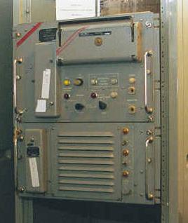
KW-26 'A' Model. (Photo courtesy www.ehistory.com . Used with permission) |
Doug Eyre describes the photo. "This is just the
receiver section (top) and its power supply (below). The transmitting unit,
nearly identical in appearance, was usually mounted directly below the
receiver. There are power meters, test switches and fuses located behind
those covers on the receiver unit. I suspect they were for the prevention
of TEMPEST. Power was applied by switches on the right side of the power
supply in between the yellow lights. Control circuits sequenced the
power in stages.
On the receiver unit, at the right side, there are two white-collared jacks. That is where the "roll around" TTY monitor was plugged in to. There are two black rotary switches. The one on the right was for plain, cipher local, and cipher remote. If you were in cipher local, the equipment only communicated with the roll around monitor. Once you put it in remote, then everything was operating normal" |
KW26-C
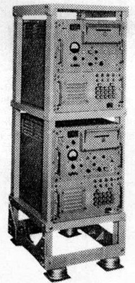
The KW-26 "C" model. |
This photo depicts a receiver (top) and transmitter (bottom).
Note all the additional fuses and switches on the power supply. (ie the lower section of both units). Those switches had to be turned on in sequence to apply power. There was a primary difference between a “B” model and a “C” model. In the “C” model, the transmitter and receiver was hinged so it could be folded down for maintenance. The switches on the front were wafer switches and were ganged anywhere between 5 and 9 deep. A maintainer hoped that he would never had to replace a switch. (Photo courtesy National Security Agency). |
 |
| Model 'C' Receiver. This example is held by the C&E Museum in Kingston Ont. Note that the air intake cover has been modified. (Photo by Jerry Proc) |
HARDWARE
The KW-26, introduced around 1958, was an on-line crypto for teleprinters and could run at speeds up to 74.2 baud. "C" versions of the machine were introduced in 1961-62. KW-26's were build by Burroughs in Paoli, PA and utilized "BiMags" which is short for Bi-stable ferro-magnetic core memory, as introduced by IBM on early mainframes. The 26's used only vacuum tubes at the onset. Later models (by 1969) incorporated transistors as the result of the many modifications to the KW-26. Transistors were used on the front core board and the input/output cards on the rear of the machine. Core boards were all classified Secret. Driver packages and power supplies were unclassified.
After a decade of service, the key card readers became pretty beat up. For cantankerous machines, a dollar bill was often used to clean the contacts and banging on a closed reader was also sometimes successful at restoring operation at "HJ" time. In one isolated case, a hammer was hung on the latching handle. Upon closing the door, the hammer was used to tap the surface of the card reader to make sure the worn pins made contact with the other side of the reader.
There were three "KAM" maintenance manuals for the KW-26. One was the theory, one the illustrated parts breakdown, and another had the circuit diagrams. It was once commented that the theory KAM was written at the 14th grade level!
Eric, KE6US, was an instructor in MOS 345. Here her describes the Speed Normalizer function. "Most of the last week of the 16 week course was devoted to the Speed Normalizer which was meant to be used on Transatlantic cables that even then were obsolete and being abandoned. It was one of the core boards which I vaguely remember went in the last slot.
Students and instructors alike dreaded this complex circuitry (more BIMAG logic) which compensated for the inherent reactance and resulting phase and time delays in such a cable. There were only two of us who took the time to figure it out and we ended up teaching it to every group that went through as a favor to other instructors. I never heard of ANYONE anywhere who had ever used the Speed Normalizer. But such is the way of the military ".
CARD READER DESCRIPTION
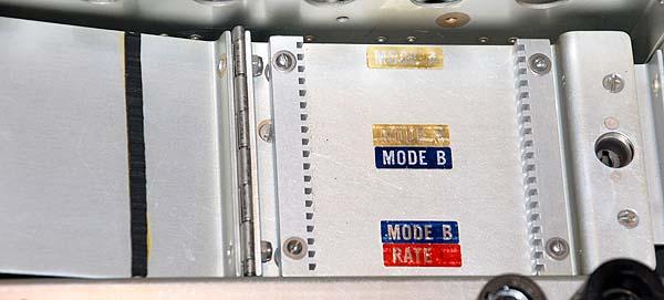
Select this link to see the inside of the card reader . The KW-26 card reader interior was split vertically in the middle. There was a raised blade on the stationary part of the card reader and a recessed blade on the hinged door. Also mounted on the door was a plate with stationary gold strips. As the hinged door opened the operator was presented with a horizontal plate, the recessed blade and a spring-loaded pin on the far right side of the door.
Every card had three holes punched on the far right side. The middle hole hooked over the spring while a stationary alignment/retainer pin on the left side of the door fitted into another hole that was always in the card. When the card was in place, it was held by the retainer on the left and the spring pin on the right. When the operator closed the door, the blades cut the card in half but the spring pins on the vertical/stationary side of the card reader and the tension from the card reader door being closed, held the card halves in place. However, once the door was opened, the two halves would separate and prevent the card from being reused. During troubleshooting, there were ways to bypass the mechanism.
1. One could fold the card in a certain fashion in order to defeat
the spring.
2. The spring could be wedged in place with a cigarette filter
3. The card reader could be left closed thus “bouncing” the pins
that were located on either side of the spring pin. Those were
the pins over the two holes on either side of the spring pin that are mentioned
above.
Steps 1, 2, or 3 were never done with a live card - only with maintenance cards.
OPERATION
Five minutes before "HJ" or crypto restart, the transmitter was recarded and a phase put up by the sending station. (The term HJ's was used initially with the 26, but later became accepted as the term for timed restarts for any system). One hoped that the receiving station was using the same sequential card deck and placed the right card in the reader of their receiver. If not, well, you can bet what fun that was. The receiving station upon receiving a phase, would get an alarm indicating that the circuit was not in sync. The receiving station replaced his card and would in turn place his transmitter in phase and replace his card. Once both units were sending a phase to each other and at the appointed HJ time, each would go to live traffic. If everything worked like it was supposed to, the the system would drop into sync and traffic would start pouring out of the Model 28 or Model 40 Teletype machines. If not, a lot of secure voice coordination went on verifying the right key cards and card numbers.
To communicate in the clear, a series of operating conditions were created. First, a FOX test would be run until the distortion/interference returned to an acceptable level. Then the distant end would ask to "GO HI" "BRAVO INDIA" (transmitter send revs from standby). When sync was achieved, receiver would send "HOTEL CHARLIE 2 (go to transmit). Then the operation was repeated on the other side of the circuit. The equipment was also susceptible to unstable power supply, and between power failure and distortion, it was not unusual to go through an entire book of key cards in 36 hours on the more unstable circuits.
One annoying problem was with the card readers. They were designed for "once-use" cards. Once the card reader was closed, it cut the key card in half. Well, on more than one occasion, a card would slip while closing the card reader door and would spoil a card in sequence. When that happened, a secure voice coordination link was immediately set up to coordinate card replacement. You knew the key card slipped when you could see the corner of the card protruding from the side of the reader. If all went well, only two cards were used during a 24 hour period. One other annoying component of the KW26 was the electro-mechanical relay used for the output. It was difficult to adjust.
Originally, the machine cost approximately $13,000 per copy in the mid 1960s . KW-26's were mainly used in major military Communications Centers (supporting TTY circuits). It required tender, loving care to keep them going. Typically, these machines needed 16 weeks of training at the crypto school. The "26-C" was rack mounted and featured handy, pull-out, sliding rails for service access. It also played an important and vital role in NATO COMSEC for many years having given reliable service well into the 1980's.
Richard Morris describes the technique of reestablishing a connection or performing an HJ by going high and blind. "This was used when you had lost sync in both directions and couldn't use a teletype to communicate in either direction. It was a particularly valuable skill when the entire site went down due to a power failure. I haven't done one in about 25 years, so I may be a bit off in my description. You start by rotating the transmitter start switch several times to get the attention of the "distant end." This was called "flagging" him and his indication when reading the incoming signal on his panel meter was that the needle would move from zero to nearly full scale and then back to zero. He acknowledged that he had seen the flag by flagging you back. You would then send a BI using the next key card. He could tell it was a BI because the input meter would wiggle at about 15% of full scale. When he had synched on your transmit signal, he would send out a BI using the following card. When you had synched on his signal you would go to operate (HC2). That would let him know he could also go to operate. He could tell because his meter needle moved quickly but randomly between about 20% and 80% of full scale. You would both do your alarm checks. Depending on the circumstances you might exchange niceties on the teletype (always finished with "CUNT" - see you next time) or if you were working on a lot of circuits at one time you would just return the circuit to the "floor." At Wildwood we would have to reset about 25 circuits by going high and blind after a power failure. Each of us reset about eight KW-26s at a time. Done by skilled operators and maintainers it could be done in only a fraction of the time that it would take if you had to make a phone call. We only had three roll around teletypes, so it would have take forever if each circuit had to wait for its turn with the teletype.
Some operators and maintainers saw going high and blind as a bit of a challenge. The question would be sent, "do you want to go high and blind?" If the answer was yes, the response would be "me first" or "you first" to designate who would use the next card and send their BI first. There was a procedure to set up a circuit by "going low" or plain text to send the initial teletype communication and then switching to cipher mode, but it wasn't used very often.
I believe that the modification required rewiring the start switch and running a number of new wires was Mod 16. It took around six to eight hours per KW-26. Truly the Mod from hell. We had about 50 online and spare KW-26s at Wildwood and it took several weeks to complete the Mod on all of them at the rate of about one for each of the three daily shifts"
MAINTENANCE PROCEDURES
Richard Morris comments on some maintenance procedures. "Each core board had about 30 to 40 bimags. Even though they taught us how to check them with the crab grabbers. We had spares if they had to be replaced, but I never saw a bimag fail except for diodes. Each bimag had a small, glass cased diode type associated with it and those were the components which failed. Occasionally, you could look carefully at each diode on a bad core board and see which diode was bad. Sometimes you could see a small black spot on the glass case when they failed.
The switch selectable meters on the front panel had multiple uses. You could use them to look at the input or output signal to the lines or the teletype or the power supply voltages (- 230, -250, and -270 volts). My recollection is that the voltages each had a switch setting and were read on the meter as a percentage of the nominal voltage.
Each crypto technician carried a "7-level" screwdriver in his front pocket to make power supply adjustments. The right way to do it was to use a multimeter, but the quick way was to use the panel meter. The seven level was also used to adjust the oscillator - but this was at your own risk. The adjustment was inside the oscillator chassis and the adjusting screw was live with about 250 volts on it. To prevent shorting, the adjustment hole in the chassis was lined with a grommet. If you touched the shaft of the screwdriver you got a real wake up. Although the prescribed tool was a tuning wand, I'm guessing that many more adjustments were made with a 7-level screwdriver than were made with the wand. (My 7-level had a length of heat shrink tubing covering most of the shaft.)
The scheduled maintenance called for a cleaning of the air filters weekly and check of the wave form of all the driver packages, the oscillator frequency, and the power supply voltages every 28 days.
My recollection of the Air Force staffing levels for the KW-26 was one technician was allocated for about every seven KW-26s. It's replacement, the KG-84, was allocated one technician for every 300 KG-84s. The introduction of the KG-84 resulted in the cross training of a large number of crypto technicians into other career fields".
This excellent narrative on KW-26 maintenance procedures is provided by Doug Eyre. "Our site in Hawaii had 80 to 100 KW-26's in one large room. We left the keys in the card readers at all times. For one thing, it made it quicker to get to the cards if we had to perform destruction. Secondly, it was much simpler to have the keys there when we were performing scheduled or unscheduled resets.
Three simple tools were used to perform basic maintenance tasks.
1. The Screwdriver - The KW-26 that I was most familiar with required that you open the transmitter drawer about 4 inches so in order to access the alarm switch and alarm clear switch. Opening the drawer required that you undo the 4 captive quarter turn screws, one per corner, and then pull the drawer open. It was not common practice to leave the drawers unlatched because of the potential for TEMPEST.
After you synched the circuit, you were required to rotate the alarm switch through all of its positions. (I don't recall the exact number, 12 or 14 or so.) You were required to stop at each position and press the clear switch. The alarm would clear and then you would go to the next position and repeat. The last few positions were designed so that they would NOT clear when the clear switch was pressed. The purpose of the alarm switch was to ensure that the encryption and alarm circuits were functional.
The screwdriver handle was ideal for "bouncing" the pins in the card reader because it did not mark up the paint on the outside of the card reader. It was ABSOLUTELY forbidden to bounce pins with live cards. Bouncing pins while troubleshooting with maintenance cards was a standard procedure. Another trick was opening the card reader and folding the crease where the card was cut so that it would hang in place. Bouncing pins was much simpler.
2. The Key Itself - It didn't take much to bounce the pins and the key itself would do the job just fine. Trouble was, it chipped the paint after a while and one of the things we always had to do if we were getting an inspection was to sand the chipped area and repaint.
3. The last item was the famous ZIPPO lighter - Guys that smoked used them all the time. They didn't chip as often as the key and worked just as well.
The military was one of the first users of the cleaner called 409.
Well, it was soon noted that the cleaner was so good that it washed off
most of the silk screening on the front of the equipment. Eventually
the depot (which by the way was Kelly AFB, TX) created giant metallic "decals"
that we put on the front of the machines when necessary. We would
have to pull off all of the switch knobs (the decal fit over everything
else) and then peel off a backing from the metallic decal and smooth it
into place on the front face of the machine. It was not aesthetically
pleasing! Further, the original 409 was very thick. In
an effort to improve it, its water content was doubled. After that
it never cleaned as well.
 |
| An array of seven KW-26's at an unidentified site. It has been confirmed that Hickam AFB was still using this machine type in 1983. (Photo courtesy National Security Agency. Colour restoration by Doug Eyre) |
When we pulled our card changes, we would have to open the card reader and pull out the two halves of the cut card and then put the new card in. It was awkward holding onto the two halves but there was enough suction on the front air intake of the receiver power supply that we would slap the four halves (two from the transmitter, two from the receiver) up on the intake and they would stay there until we buttoned everything up.
Sometimes the transmitter drawer had to be opened in order to perform an alarm check. There were occasions when the cards would be jarred enough to slide down off of the intake grill and slip in between the circuit cards in the transmitter. That wasn't fun because it meant that we would have to pull the circuit down and power off the equipment to get into the card cage extract the card halves. It didn't please one's supervisor to hear why there was excessive downtime on a circuit due to operator error.
While in training, we needed some instruction on how to properly fold the pages of the KAM (maintenance manual). When unfolded, some of the pages stretched for 6 feet on the lab table. With the bi-mags, we had to bring a roll of pennies with us to class to “chase pennies” on the schematics. The symbol for a bi-mag was a circle and we would shuffle pennies all over the drawing to identify the logic flow. IT WAS A NIGHTMARE! Once you got out to the field, all we had to do is swap out the bad boards and send them back to the depot.
The KW-26 was robust enough that you could literally give it a bath. We had some units in Base Ops on the flight line at Hickam AFB. Airplane engines in the 1960’s were filthy and soot would get all over everything. Maintenance personnel would take out a complete KW-26 unit and bring it over to the main communications center where we had 80 or so of them. They would take out all of the circuit boards, oscillators, relays, pull off the tube shields then pull out all of the tubes. They would then hand wash each unit in a large metal tub of warm water with pinolium and then rinse it off in clear water. Compressed air was used to blow dry everything. The KW-26's would then be reassembled and the next 6 hours would be spent making sure that all was well. After that it would be taken back to Base Ops. What amazed me was the first time that I saw a machine being washed. As far as I know, this was only done to the machines we had at Base Ops (about 4 of them if I am not mistaken) and I never saw one fail to come back up.
All of my experiences were with the 'B' and 'C' models. I was told that there was a D model which was fitted with a 400 Hz power supply for use aboard aircraft. I have no way of believing that a KW-26 would or could be used aboard an aircraft but then stranger things have been known to happen! The problem would have been the transmission media. You would require a two way, hot link, 24/7. The KW-26 was not forgiving of line problems! "
[Another submitter says that ten KW-26-Ds were installed on Air Force
One for use while the plane was on the ground at Andrews.]
Doug also relates some anecdotes. "The KW-26 was chock full of electron
tubes. There were two 6197 tubes on each AAL board. (A 6197 was the
industrial version of the 6CL6 power pentode). There were probably
12 to 16 AAL's in the equipment but I cannot remember the exact quantity.
Electron tubes developed intermittent shorts and the slightest vibration
would trigger the condition. Bad tubes would cause the equipment
to alarm out (transmitter) or lose sync (receiver) and the KW-26 would
need a reset. Each time the transmitter drawer was pulled out and closed
for an alarm check, that was an opportunity to discover if any of the tubes
had developed intermittent shorts. If you shut the drawer and the equipment
alarmed out, the practice was to patch to a spare KW-26 then troubleshoot
the primary machine.
 |
 |
 |
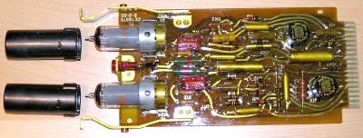 |
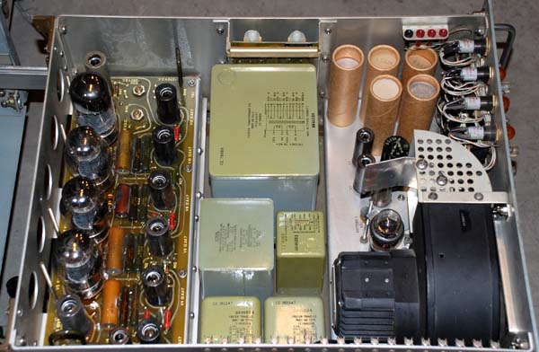
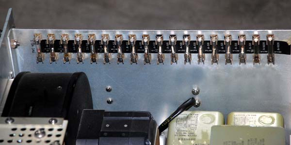
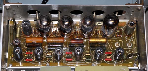
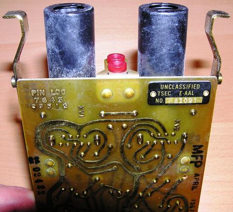
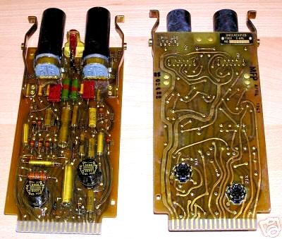
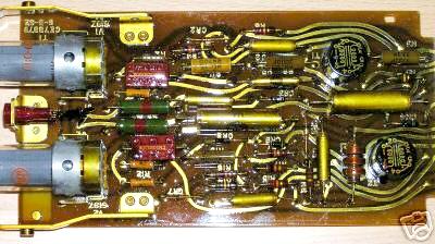
| Various views of an E-AAL board. It provided steady, timed pulses.
There were several of them on the left and right back two/thirds of the
transmitter and receiver chassis.
Squeezing the levers unlocked the card from its slot. The two black, circular transformers were the only removable items on the board that didn't have to be unsoldered. In the top photo, note the designation MFP and a date. This means the board was Moisture/Fungus Proofed in April 1961. MFP was a shellac-type coating which sealed just about everything. It was difficult to remove if a component had to be desoldered. MFP had to be reapplied to the cleaned area once a repair was completed. (Photos courtesy E-bay) |
I was called in to work at RAF Welford, UK about two in the morning by a relatively new operator. Since his transmitter had been alarming out, he had patched to spare and called me in. Well, I threw in the maintenance cards and started to check things out. Sure enough, slam the drawer and it alarmed out. After doing a reset, I pulled the drawer fully out. I knew it was a bad tube. Without thinking, I went to the tool board and grabbed a small ball peen hammer and started lightly tapping the tubes until I found the bad one.
After congratulating myself, I turned around and there was the very perplexed operator watching this crypto maintenance troop beating on his equipment with a ball peen hammer. I didn't even try to explain. I simply replaced the tube, checked the equipment over, put everything back in its place and went home. On my way out the door, I told the operator that if it gave him any more trouble, not to worry because if the ball peen hammer didn't fix it, we had the 10 pound destruction sledgehammer on the wall that I could use. We left it at that and I didn't get any more calls that particular morning.
The KW-26 also used four, 6550 power tetrode tubes. One always knew when they were bad because they would go milky white. A modification to the power supply was issued in the 1970's which called for the installation of a Plexiglas shield over the top of the five, big, oil filled capacitors in the corner of the power supply. On rare occasions their tops would rupture and spray the hot oil dielectric right into the maintainer's face. I once witnessed the event personally during my watch. Fortunately, the guy was wearing glasses so it didn't hurt his eyes but he had some pretty bad burns on his face that took a while to heal".
Doug goes on to say: "We had a power surge at Hickam AFB back around 1966-67 that wiped out the entire crypto shop. (Rumor said that that commercial power and military power, which were supposed to be separate, somehow added algebraically and zapped our 120 AC equipment with 240 AC. Don't know how true that was but our equipment was FRIED!)
They called us out of the barracks and we came as we were. I was in shower flops, shorts and a T-shirt with my badge. We pulled ALL of the AAL packs out of ALL of the equipment and had them in boxes. We had one running KW-26 that I sat in front of with an O-scope and just plugged a pack in, checked it, put it in a good or bad pile. The guy next to me would take the good ones and pass them on to guys to rebuild the bad gear. Another guy was pulling tube covers and pulling tubes and replacing them and they would go back into the pile to be checked. This was no small feat because those tubes and tube shields got HOT!
It took us about 36 hours to get all of the equipment/circuits back up and running. We had folks scouring the island of Oahu trying to scrounge up 6197s. We got them from the Army, the Navy, and the Marines as well as other AF sites by the caseload.
And the paperwork was not forgotten. We had two guys sitting at the workbench filling out AFTO Form 349s (which by the way are still in use by the USAF today in a slightly modified format) to document all of the maintenance and troubleshooting and parts replaced. There must have been about 20-25 of us working around the clock to bring the equipment back on line. A small insignificant effort in the big scheme of things but we felt like we had really accomplished something".
James Gabrisch recalls one of the machine's modifications. "There were two relays (line in/line out) plugged into a separate module (the E-BAT assy) that bolted to the under-side of the unit. These relays were pretty generic, and were used in a lot of different teletype gear. At some point between 1977-79, we did a mass conversion from the electromechanical relays to solid-state versions. They were the same size and shape, plugged into same octal socket. It was a much better deal, as those older relays were a pain to rebuild".
A WORD ON BI-MAGS
George Mace describes the Bi-Mags and how to test them. "The Bi-Mags (ferrite cores) of the KW-26 were all about three quarters (3/4) of an inch square, with a 3/8 inch ferrite core containing up to six windings. Twelve pins protruded from this clear epoxy resin filled cube for mounting to the printed circuit board. You could look into the clear resin and see the ferrite ring core, with small windings. These Bi-Mag cubes were all BLACK and physically looked alike, however they had different functions and identifying CE part numbers printed on top of them.
To test the bimags, a "grab claw" tool was used. Each claw had a wire extending to a Navy gray cylindrical housing which contained a size (C or D ?) 1 ½ volt battery and a switch. By pushing the switch you could change the state of the Bi-Mag, or lock it in "one" state. During the early days of the KW-26 we made our own (one maker) with a 'D' size battery and taped two leads to it, spaced just far enough apart to span across the selected pins!
Such a device was necessary to trouble shoot the KW-26 printed circuit boards, which could be raised on extender boards, above all other boards. This extender also turned the board 180 degrees so the printed circuit tracks and pins face the technician.
