KW-7 (Orestes)
The Orestes cryptosystem employed
the KW-7. It was an on-line, send/receive crypto unit installed in shore
stations and aboard ships. In one application, it was used for ship to
shore and for intership radioteletype communications. To send messages
over a secure UHF teletype circuit, a model 28 Teletype or reader (T-D)
sent the prepared message to the KW-7 which in turn keyed a UHF transmitter
in the AM mode. The KW-7 was also used aboard aircraft such as EC/RC-135's.
KW-7's saw service in three variants. The original version used wire
cords to set the daily key. Next, the plugblock version was introduced
while the last variant used a paper card reader. Externally,
one could tell the machines apart by the front covers. The original version
of the machine had a flat, front cover. When the plugblock version
was introduced the cover had a small square bulge. When card readers were
introduced, the cover shape changed to a large rectangular bulge.
 |
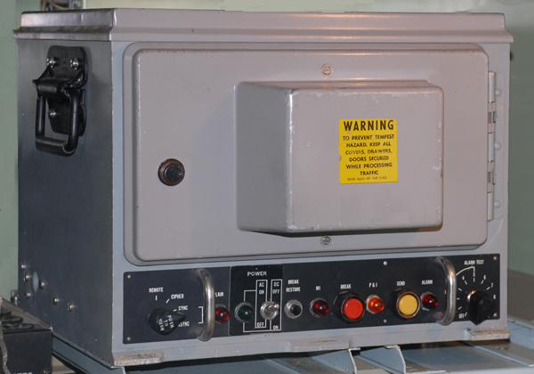
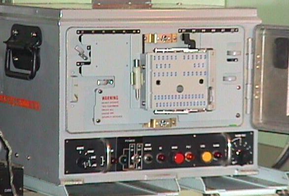
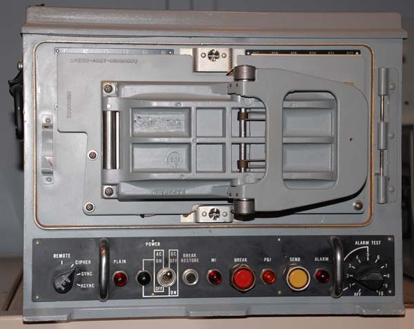
| Above: This is the card reader version of
the KW-7. . Both examples are on display at the Communications and Electronics
Museum in Kingston, Ontario. (Photos by Jerry Proc) |
 |
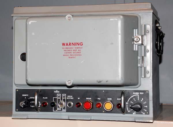
| Plugblock version. The KW-7 was not a totally
synchronous unit, therefore, it required a phasing signal to be sent in
order to attain a lock on the received signal. top. The circuitry
was all solid-state and fit in a fairly rugged housing that featured a
Tempest-sealed lid on top, removable for servicing. (Photo by Jerry
Proc)
Examples of the plugblock and card reader versions of the KW-7 can
be found at the Communications and Electronics Museum in Kingston, Ont. |
SETTING THE DAILY KEY
THE WIRE CORD VERSION
The original KW-7 had 30 fixed wires coming
out of the bottom half of the key area. Using a daily key list, the operator
plugged the wires into the top half a flat block. Many operators joked
that part of the KW-7 course consisted of basket weaving since that seemed
to be a prerequisite skill for this task. The task of coding the plugblocks
was sometimes referred to as knitting. The wires were about 14 to
18 inches long and it took forever to get them all plugged in and still
be able to close the door over top of them. There were metal loops
provided to help shorten the slack but it was still difficult to get them
packed in.
Many a time, a KW-7 used in flying command
posts for TTY traffic would be pulled in for maintenance
only to discover there were little black loops of wire hanging outside
of the edge of the locked door because it was such a tight fit inside.
This was frowned on since the purpose of the gasket was to reduce Tempest.
PLUGBOARD VERSION (?)
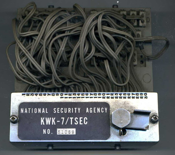
A former KW-7 operator, indicates that there was a variant of the
plugboard circa 1969. It was likely a predecessor to the plugblock
version and does not appear to be commonly known. He recalls " the black
cables were entirely separate from the box both ends. The bottom
end of one cable is shown in the illustration below. The numbers were aligned
perpendicular to the cable so that when properly plugged in, they were
easy to read. As with all of the plugs, it was a "bear" to get all of them
in place and still be able to lock the door without pinching the
cables". Any collaboration on this cabling scheme would be appreciated.
Contact: Jerry.Proc@sympatico.ca . Did this system have any
official name?
He also indicates that his KW-7 came with a special accessory. "The
only other attachment I had was a thermite grenade, which sat atop the
box the whole time I was with it. Im pretty certain that this fitting
was Standard Operating Procedure after the USS Pueblo was captured by the
North Koreans in 1968.
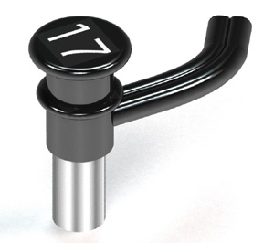 |
| This image depicts the connector type used at one end of the patch
cable. The other end would have been identical. |
THE PLUGBLOCK VERSION
Plugblocks had to be set up by hand and were
not considered to be a fun job. However, the introduction of the plugblock
offered two important features:
First, it reduced the damage to the cords.
Second and more importantly, it allowed the key to be set up in advance
on a spare block thus allowing the key to be changed in moments instead
of the 10 to 15 minutes it took to manually patch and route the cables
in the original variant. This allowed the operator to have the blocks "pre-corded"
before the start of the next crypto cycle (HJ). A locking lever at
the right side of the plugblock was lifted and swung to the left. This
permitted the entire plugboard block to be removed and another one inserted.
 |
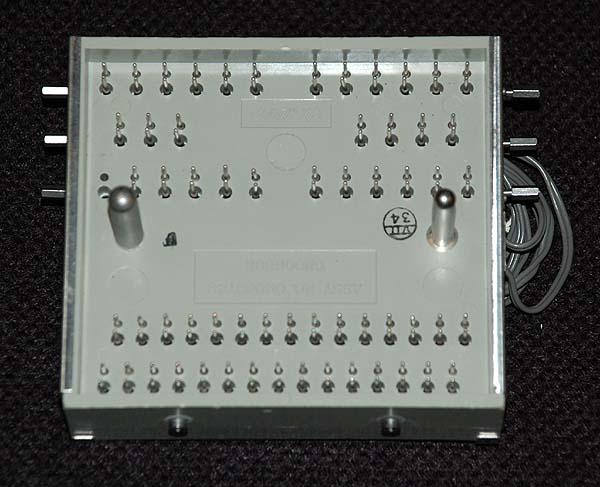
| KWK-7 plugblock assembly. Once wired up, this mated with
the plugboard in the machine and was locked in place. The three silver
coloured bars were used as retainers for the plug wire connectors.
(Photo
by Jerry Proc) |
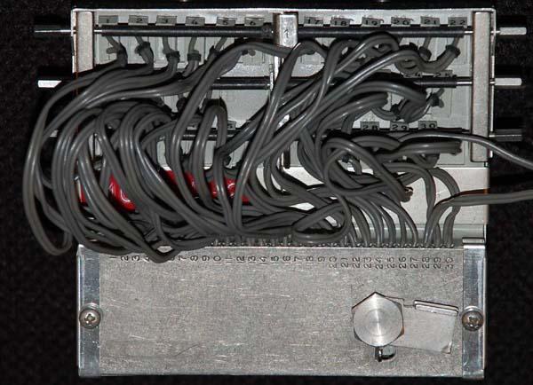
|
|
Contact side of plugblock assembly. (Photo by Jerry Proc)
|
 |
| This image illustrates the markings on the plugboatd.
(E-bay
photo) |
In the photo titled "A close-up view
of the mating plugblockmodule", the little white handled tool (clipped
to the left of the plugblock) was used to push the little white square
jacks out of the block. Flat face and block modified KW-7s were
totally compatible with each other and used the same key lists.
A KW-7 with fitted with a card reader could
not communicate with a machine fitted with a plugblock because there were
many more permutations available with the card reader than with the plugblock
or the 30 cables.
 |
|
A plugblock version of the KW-7. (Photo
courtesy of the Communications and Electronics Museum, Kingston, Ontario).
|
|
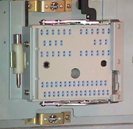
| A close-up view of the mating plugblock module.
The locking handle is easily seen. (Photo courtesy of the Communications
and Electronics Museum, Kingston, Ontario). |
For maintenance, there was a
back-to-back reader that would accept two plug blocks and it would test
to see if both blocks were sequenced identically. If not, an alarm would
sound and the tech had proceeded to search for a broken wire. Crypto techs
considered this to be a real pain when troubleshooting. There were clumps
of cord plugged all over the board and each cord would have to be
wiggled until the intermittent short was located. Each cord had two
conductors with a numbered pin at the end. If one broke, you could not
just get a spare cord, you had to get one with the correct number at the
end of it. To further add to frustration, a punch card machine could not
communicate with a plug board machine!
 |
This KW-7 test bed was made by SUB NDA West,
Denmark around 1987-88 in order to test the KWK plug board. (Photo by
Henrik Teller ) |
Steve Gardner, who formerly maintained
the KW-7 offers these comments. "You seldom got the plugblock correctly
routed the first time. It would work - BUT you couldn't get
the cover closed! Rerouting some of the patch cords would cure
the problem, but it required a new BI when you did it. The KW-7 does not
provide "Traffic Flow Security." If it is not sending a message
it spits out a "one mark" Baudot pattern, the same as BI pattern".
A KW-7 maintainer in Europe relates his maintenance
experiences with the machine. "We had bi-stable relays in the KW-7 which
switched the loop current between the mark and space state. Rarely
did we have problems with the KW-7, but if I had to repair one, it was
most likely one of those two relays that had a dirty contact and produced
gash on the Telex line. We opened the top cover of the KW-7, pulled them
out and unscrewed the aluminum cylindrical cover. They were then attached
to a small tester which had a little 5 cm cathode ray tube.
It was solely designed for testing the KW-7 relays. When a test signal
was applied, lots of spikes and noise were observed on bad relays instead
of nice rectangular blocks on the CRT. Next, we took a piece of non-perforated,
5 level paper tape, sprayed it with contact spray and moved it up and down
between the contacts. Bit by bit, the rectangles on the CRT had fewer spikes.
The process was sustained until the relay was free from noise. That KW-7
would then work (around 16 hours per day) perfectly for another 3
or 4 months. I can't remember actually replacing a relay. We always used
all possible tricks to get those things running again".
THE CARD READER VERSION
Introduced in 1977-1979, the daily
key was changed by installing a fresh key card - a vast improvement over
the plugboard method. The card reader modified KW-7 was not only
easier to operate in regards to key changes but it was slightly more secure
as a result of the additional permutations it provided.
|
|
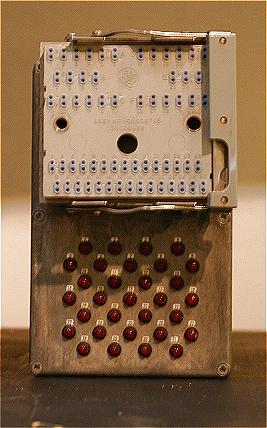
The front door has been removed exposing the card door latching
mechanism.
|
 |
| The card reader door in the open position. |
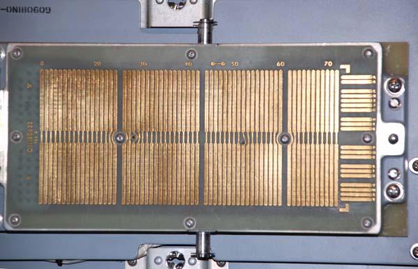 |
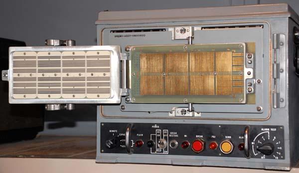
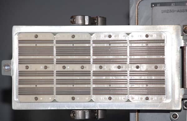
| Above and below: Close up views of the card reader contact
assembly. Apparently, the contacts on the door (bottom
photo) are "conductive rubber". |
 |
| All photos in this table by Jerry Proc |
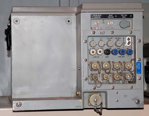 |
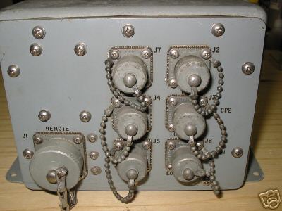
| Rear view: Unfortunately the power supply is missing. It connects
to the KW-7 via a 'D' shell connector. |
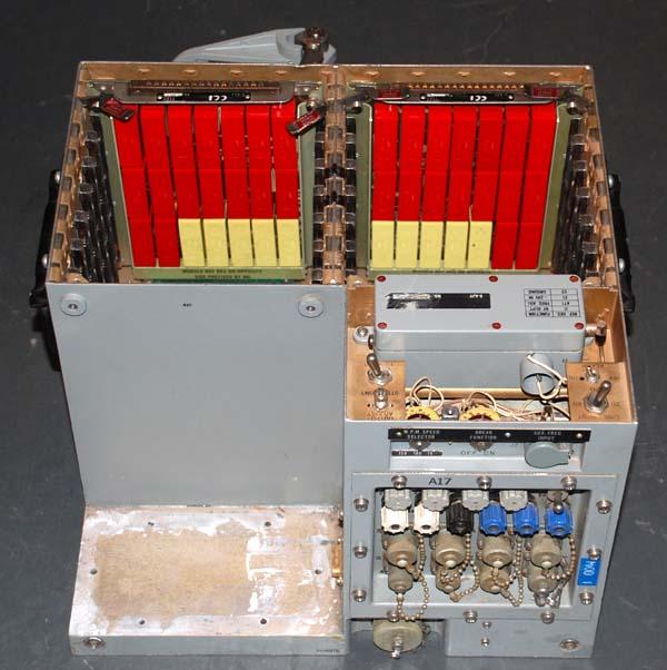 |
| Rear view showing the placement of the clock module
and two E-AJJ boards. |
 |
| A closer view of the E-AJJ modules which employed "flyball"
technology. |
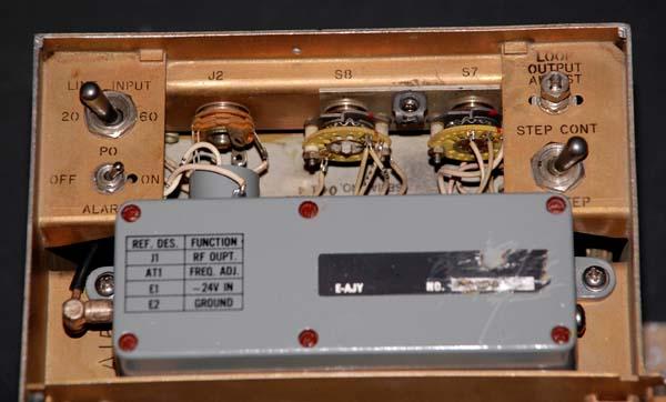 |
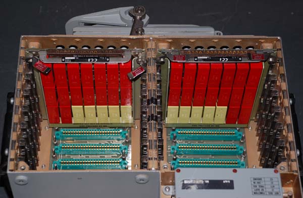
| Close up view of the clock module compartment. Note the
switch at the left top which could select 20 or 60 milliamps (input) current
loops. The step/cont switch is used during maintenance. |
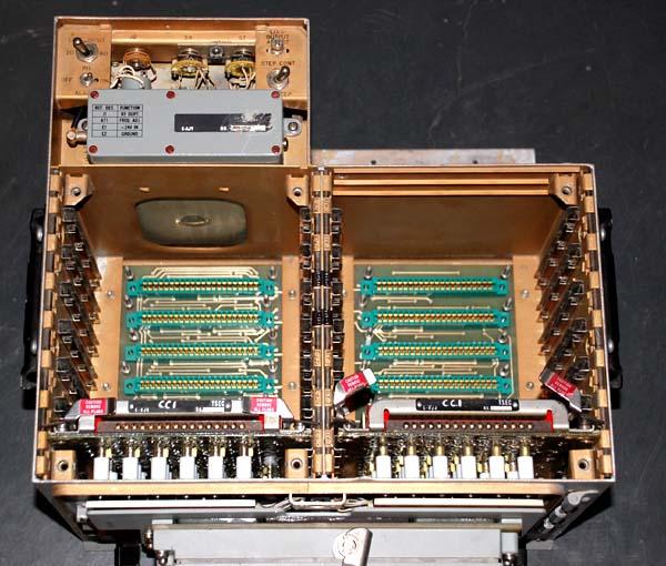 |
| Top view looking towards rear. |
 |
|
Closeup of rear connectors and switches.
|
|
All photos in this table by Jerry Proc
|
When new, these machines cost around $4,500 a piece and
required 6 to 8 weeks of training in order to maintain them. KW-7's
were also used in U.S. military radio shelters like the TRC-136, the GRC-122
and the GRC-142. The GRC-142 or GRC-122 used one or two KW-7s in a simplex
or full-duplex HF radio link In either case they would have been
attached to a GRC-106 radio set. Early shelter versions use Kleinschmidt
teletypes and later versions use UGC-74 teleprinters. The KW-7
was self-synchronizing to the extent that whenever the other fellow stops
sending, you push a button which sends out an initialization sequence to
the other end to put it in sync.
On close inspection, the red and yellow pushbutton
switches on the base of the machine are surrounded by large protective
hex nuts. That was a modification that was added shortly after the machines
were placed in service aboard the various airborne command post aircraft
(EC-135 variants). Seems that the equipment
was mounted close to the floor and it was easier for an operator to press
those buttons with the toe of his/her boot than it was to bend over and
press them with a fingertip. This repeated action resulted in the
mashing of the button faces and that would cause the indicator lamp to
short out which put the machine out of commission. To prevent the
problem, a modification was issued to secure a collar to both switches
so that the boot toe could no longer mash it.
Jim Dell, who served in the Royal New Zealand
says that "the BID/660/1 was used in lieu of the KW-7 in our major units.
The advantage of the BID/660/1 was that you could also employ Traffic FlowSecurity
(TFS) the same as the KW-37T. This meant that you didn't have to rephase
to resync and also you didn't need to keep a rubber band on the Transmit
button as you did with the KW-7 between traffic! TFS was only ever used
in overt operations".
Jerry Kemp used to maintain
the KW-7. He provides some insight on the use of the SEND button. "Aircraft
personnel apparently had a hell of a time keeping KW-7's synced.
So much so, that they would take the cap from a Bic ball point pen, and
jam it into the crevice of the SEND button, keeping the unit(s) syncing
all the time it wasn't in actual use. This activity caused all kinds of
havoc on the mechanical relays, located on the bottom side of the chassis.
I can honestly state that there wasn't a KW-7 that ever came in for maintenance
and/or PMI, that I didn't spend more time than anything getting those mechanical
relays back in operation again.
LOCKING KEYS
The security lock on the permuter cover is
unusual. Most common locks have one row of pins, corresponding to one row
of bumps/serrations on one side of the key.
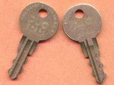 |
| This photo illustrates the unusual keys used
on the KW-7 lock. (Keys donated by Tom Chirhart, Stafford, VA. Photo
by Jerry Proc) |
The KW-7 lock has three rows of pins, two rows
on one side of the key and one row on the other side of the key. The key
is next to impossible to duplicate by the average locksmith because cutting
that third row of bumps/serrations can't be done on a regular key cutting
machine. By 1988, KW7's were being replaced by KG-84's.
SPECIFICATIONS:
Keying method: Cables, keylist.
Service life: 1960's - 1990's. It is
confirmed that the KW-7 was still in use as late as February 1993 at HQ
PACAF
Input: Teletype
Output: On-line encrypted teletype.
Speed: 50+ wpm.
Weight: 77 pounds with the permuter block
and 82 pounds with the card reader.
Applications: Strategic and tactical environments.
Note: Typically used to send encrypted teletype
from ship-to-shore.
Dick Morris comments on the weight. "The weight
of the KW-7 was significant to those of us who had to carry them into the
EC-135 command post aircraft through the crew hatch. The crew hatch door
was at the left side of the aircraft under the cockpit. It hinged downward
and had a ladder with about four steps. The way to get into the plane with
a KW-7 was to hang onto one handle of the KW-7
with one hand and grab a rung of the ladder with the other.
When you were standing on the first step of
the ladder, you leaned against the back wall of the crew hatch which let
you release your hand from the ladder and grab the next rung. When your
shoulders were a bit above the floor of the plane, you leaned against the
wall behind you and lifted the KW-7 onto the floor in front of you. Not
a task for the faint of heart".
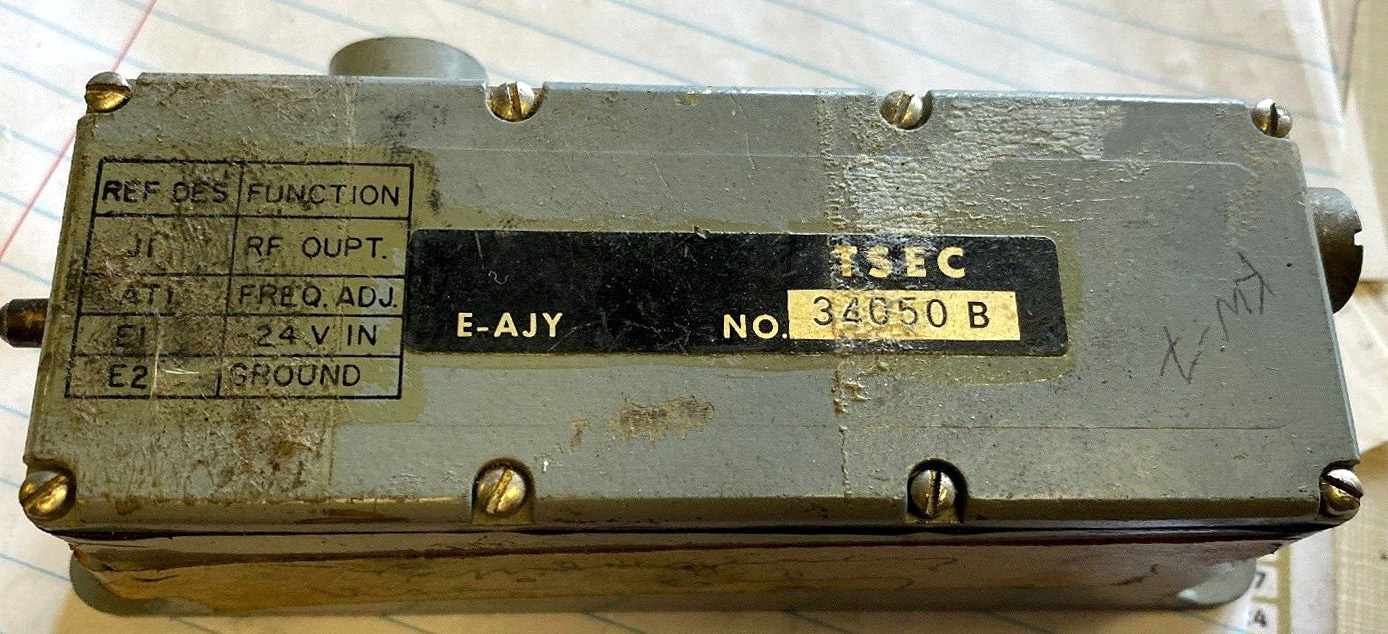
CLOCK MODULE (E-AJY)
There were at least two known variants of the
clock module whose designator is E-AJY. It produced a precise 1 MHz signal.
 |
|
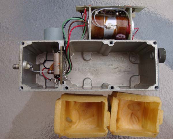
| KW-7 clock module - E-AJY..
These failed quite frequently. The internal temperature was monitored by
a thermostat consisting of a mercury thermometer with contacts. It was
calibrated to shut off the oven at around 65 degrees C (?). Sometimes
the thermostat would malfunction, thus overheating and melting the Styrofoam
covering the 1 MHz crystal. Some identification has been removed. (All
photos in this table by Jerry Myers) |
 |
 |
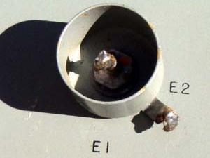
| E-AJY- Detail
of E1/E2 power input connection. |
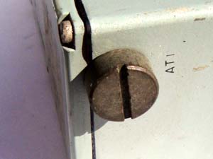
E-AJY.- When the screw is
removed, it allows access to a glass piston trimmer inside thus allowing
the module to be calibrated to the precise frequency. |
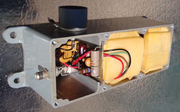 |
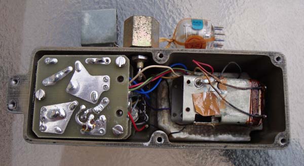
| E-AJY-The leftmost compartment
contains input power and output RF circuit board. |
 |
| E-AJY-Completely unpacked. |
 |
| E-AJY-Above and below: Two
views of the oven assembly which resides in the middle compartment. |
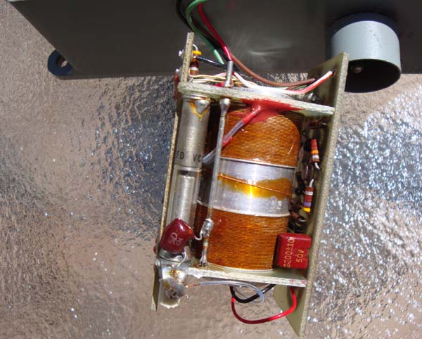 |
| E-AJY- clock module internal
views. |
 |
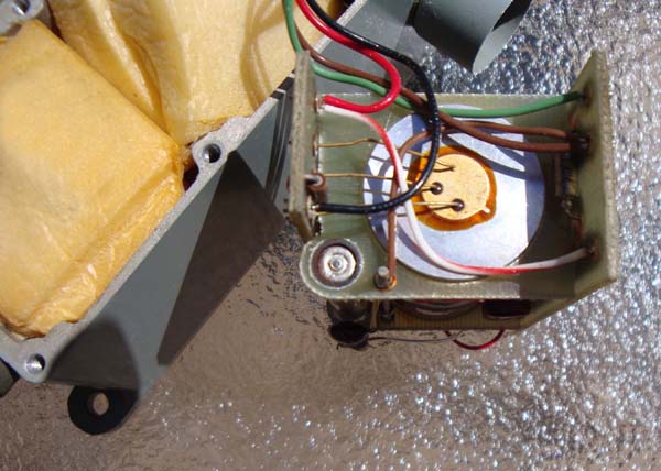
| E-AJY-The clock module had at least
one known variant which is shown here. What appears as a vacuum tube is
actually a crystal in a glass enclosure fitted with a 7 pin tube-style
plug. Nylon lacing cord is looped around the crystal to assist in
its removal. This oven had a short in the mercury thermostat thus melting
some of the styrofoam at the bottom of the compartment. |
 |
| E-AJY-The crystal plugged
into a 7 pin tube socket mounted at the bottom of the oven compartment. |
| All photos in this this table by Jerry Myers |
Jerry Myers explains the mercury thermostat version of the
clock module. "The thermostat was very short and had a bulb just like any
standard mercury thermometer except there were two wires imbedded into
the glass side at two places. These wires would make contact with the mercury
column when it rose due to the heating of the oven. The mercury would
make contact with the first wire then, after additional heating, it would
make contact with the second wire. This shorted the connection to a transistor
and killed the power to the oven. After prolonged cycles, the mercury
would sometimes fail to make contact with one of the wires thus allowing
the oven to overheat until the thermometer broke due to the excessive
pressure. At this point you the technician would not be able
to adjust the module for a 1 MHz output".
TRANSISTORS
The KW-7 used circuit boards that employed potted modules.
One of the transistor types found in the potted modules was the 2N404.
Introduced by RCA in 1957, it was a Germanium PNP alloy transistor
in a TO-5 case. Soon adopted as an industry standard and sold in the
millions. Multiple companies started to produce equivalent
devices (ie Raytheon, Sylvania, Tungsol, TI, GE, General Instruments, and
others).
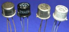 |
| Photo courtesy Transistor Museum |
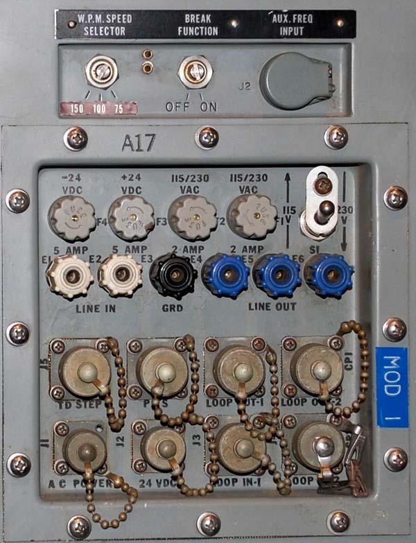
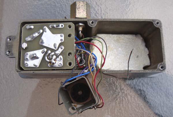
POWER SUPPLY
The KW-7 contained an integral power supply capable of running on
120 VAC 60 Hz or 24 VDC. It was mounted on the chassis of the KW-7, but
shrouded in its own enclosure and removable from the KW-7 without disturbing
anything else. Former technicians who maintained the KW-7 speak highly
of the internal power supply reliability since they never had to fix one.
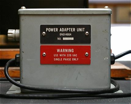 |
| In Europe, the KW-7 was operated with an external 220 to 110
VAC step down transformer. It's dimensions are approximately 15 x 15 x
15cm (Photo by Henrik Teller ) |
In Belgium, the Comm shelter was fitted with both 24 VDC
and 220 VAC. The 220v was provided by a small generator on a trailer
A power supply connected to the 220v mains would charge the batteries.
Normally the equipment always ran on 220v, but when the generator went
down, an inverter transformed the 24v from the batteries into 220v for
the equipment, the KW-7 power adapter and some other gear. Although a few
things ran directly on the 24 VDC mains, the KW-7 was always used on 220v.
(Our teleprinters needed 220v, so we had to have 220 anyway).
The KW-7 provided either a 20 or 60 ma loop current.
MANUALS
KAM-143B/TSEC Description, Installation, & Operation
of TSEC/KW-7 (a 1967 manual) KAM-144B/TSEC Preventive Maintenance
& Troubleshooting of TSEC/KW-7
KAM-145C/TSEC Operating Instructions for TSEC/KW-7
Repair and Maintenance Manual for the KW-7
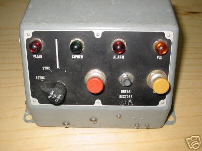
REMOTE CONTROL PANEL

|

|
| Photo by <logandad@gte.net> |
<Photo by logandad@gte.net> |
This is the cockpit remote control unit which could operate the KW-7.
It was made by Collins. The Orestes system, used in strategic and
tactical environments, was not limited to ships and land based systems
but also used in aircraft. The panel has 16 Clare Pendar switches: they
are a combination of DPST, 4PST, latching, momentary and all are illuminated.
Face plate is backlit as evidenced in the right photo. Switches have the
following labels, TTY / KEY, KW-7, MODEM TEST, POWER, KW-7, 700B-2 1, KW-7
2, 700B-2 2, 700B-4, TE-204, KW-7 1, 700B-2 1, 700B-4, TE-204, KW-7 2 .
Dick Morris adds. "The Collins remote unit depicted above was actually
part of the USAF ARA-60 system along with the TE-204A-2 synchronous modem.
This system was on the airborne command post aircraft. The code name for
the planes that I worked on at RAF Mildenhall in the U.K. was Silk Purse.
Similar planes at Offut AFB were code named Looking Glass."
KWX-7
The KWX-7 was another type of remote control for the KW-7.
 |
|
KWX-7 Front View. (Photo via E-bay)
|
 |
|
KWX-7 Rear View. (Photo via E-bay)
|
Mike Fite, MSG, USA (Retired) trained on the KW-7. He rerlates some
of his experiences. "I was stationed at Ft Gordon, GA for AIT (Radio Teletype
Operator) in early 1970. We were trained on the Plug Wire Cord version
of the KW-7. The classroom was enclosed within a chain link fence with
razor wire on top and an armed MP posted outside. We were not allowed to
bring ANYTHING into the classroom that was capable of capturing an image
(no ID Card, no paper, no photos/pictures of girlfriends, etc.) nor could
we take notes. All instruction was memorization-based. At the end of the
course we participated in a 2 week FTX in order to graduate. At the FTX
site we used both the 26 Delta HF radio and the 106 (with the KW 7). Just
as with the classroom, the area of operations was fenced-in and patrolled
by an armed MP, 24/7. As other folks have already noted, the changing of
the wires was a real pain. We had to be very careful in unplugging the
wires as well a "combing/separating" the wires through our fingers. An
equal amount of care was required when plugging the wires back-in due to
the delicate nature of the terminals. It was EXTREMELY frustrating to go
through the "key changing" process and not be able to communicate due to
having "crossed" a couple of the wires".
KW-7 IN SERVICE
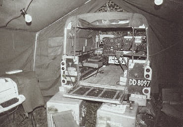 |
| This is a photo of an New Zealand Army FFR
(Fitted For Radio) vehicle showing the Land Rover backed into an 11 foot
by 11 foot tent. On the ground, immediately below the tailgate, are two
carrying cases for the KW-7. The KW-7 is sitting on the table with the
dust cover in place. To the left of the KW-7 is a Kleinschmidt teleprinter.
This FFR belonged to 2 Sig Sqn. (Photo courtesy Ian Fraser, RNZ
Signals Ret'd. E-mail: <ifra1616(at)bigpond.net.au>) |
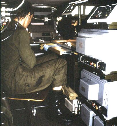 |
| A Landrover 109 SIII was used as a teletype van by 2 (DA) Signal
Battalion of the Danish Army. Above the KW-7 stack and over to the left
are two Siemens T-56 line converters. To the left of the operator is one
of two Siemens T100Z teletypes. (Photo courtesy Royal Signals
Historical Collection, Fredericia, Denmark) |
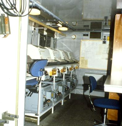 |
| This teletype van was used by 2 (DA) Signal Battalion of the Danish
Army. It was a Danish produced shelter (known as the M/83) and mounted
on a Magirus-Deutz 168M11FAL chassis.
At the left, and only partially visible behind the blue chair was
a Siemens T100- STV20 teletype and a Siemens M190 crypto equipment which
used keytape. It was only used for preparing messages (poking). Behind
that,
are four operator positions each with a Lorenz LO-133 teletype and
a KW-7. To the right (and not visible) were two positions with Lorenz LO-133
teletypes and KW-7. (Photo courtesy Royal Signals Historical
Collection, Fredericia, Denmark) |
For additional information on the vehicles mentioned in the photo
captions, please visit the Danish
Army Vehicles Homepage of Henrik Teller.
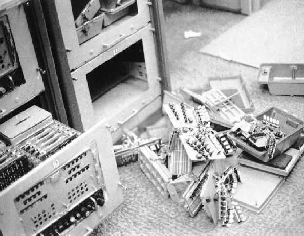 |
| When the U.S. Embassy in Tehran was stormed in 1979, the crypto
equipment or key pieces of it were destroyed by the communicators. That's
a KW-7 in the lower left portion of the picture. The front panel
has been removed along with the critical key generator boards. It would
appear that the personnel that ran the commo site knew what to do when
overrun. (Photo courtesy Memory Hole web site). |
As a result of the capture of the USS Pueblo in 1968 by the North Koreans,
the following cryptographic systems were compromised: KL-47, KW-7, KWR-37
and KG-14. An NSA report dated July 1969, details the cryptographic losses.
A copy of this report can
be found here.
For additional information on the KW-7. please visit the Cryptomuseum
web page. http://www.cryptomuseum.com/crypto/usa/kw7/index.htm
Credits and References:
1) Lee K. Shuster -
Salt Lake City Utah.
2) David Ross, N7EPI
3) Tom Chirhart - Stafford,
Virginia
4) Steve Gardner. E-mail: steveg(at)dfa-inc.com
5) Jim Dell, ZL4JAD <dinger69(at)xtra.co.nz>
6) Memory Hole web site: http://www.thememoryhole.org/espionage_den/embassy1.html
7) Henrik Teller <henrik_teller(at)vip.cybercity.dk>
8) Gregory W. Moore <gwmoore(at)moorefelines.com>
9) Dick Morris <rmorris(at)alaska.net>
10) Jerry Myers <jerry1joan(at)aol.com>
11) 2N404 photo courtesy http://semiconductormuseum.com/MuseumStore/MuseumStore_2N404_Index.htm
12) John Dill < jdill1927(at)bellsouth.net>
13) James Gabrisch <cpgarbanzo(at)sbcglobal.net>
14) Communications and Electronics Museum, Kingston
Ontario.
15) KW-7 manual info William J. Neill <wjneill(at)consolidated.net>
16) Jerry Kemp <cryptosys(at)oryx.us>
Back To Menu
Page
Sept 6/24