Click on image to fire the guns.
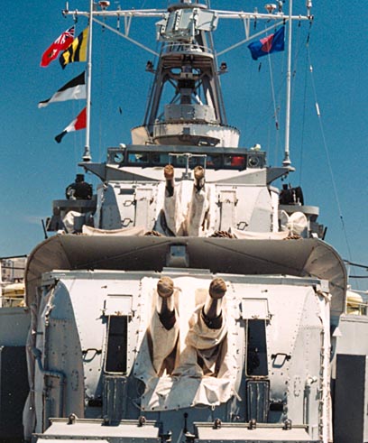 Standing at the bow and looking aft, are HAIDA's 4 inch guns. The lower
mount is called 'A' gun and the upper mount is 'B' gun. These guns
had a maximum range of 8 nautical miles.
Standing at the bow and looking aft, are HAIDA's 4 inch guns. The lower
mount is called 'A' gun and the upper mount is 'B' gun. These guns
had a maximum range of 8 nautical miles.
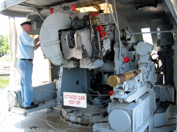
Technically speaking, these are twin, four inch HA/LA Mk 16 gun mounts. HA means high angle and LA means low angle. For these guns, the HA was 85 degrees and the LA was -10 degrees. When HAIDA was first commissioned, she was fitted with twin, 4.7 inch guns in the 'A' and 'B' mounts. These guns could only be elevated to an angle of 30 degrees due to the ammunition tray which protruded behind the breech. This angle was sufficient when the principal adversary was other surface ships, however, the 4.7 inch gun barrel could not be elevated sufficiently to shoot at aircraft. Prior to her tour of duty in Korea, Haida's forward 4.7 inch guns were replaced with the dual 4 inch mounts that are seen today. When fired, a 4 inch projectile left the muzzle at 2,610 feet per second and produced a "deck thrust" in the magnitude of 60 tons when the barrel was elevated to 45 degrees. Recoil was constant but the deck thrust varied with the angle of the gun. The range of the projectile could be upwards of 8 miles, again, depending on the barrel elevation. HAIDA's gunners had to be in good physical condition in order to load the gun because a 4 inch shell weighed 66 pounds. For the crew below decks, the firing of the guns could be best described as "being inside a 45 gallon drum and having someone pound it on the outside with a sledge hammer". John Clark served in HMCS IROQUOIS during WWII as a stoker and also as a gunner for the 4.7 inch guns . He recalls the hardships which were suffered during a gun firing. "I served both as a member of "Y" gun crew and also hoisting ammunition to "B" gun at different times when I was not doing my regular watch in #2 Boiler room. We had no ear protection and of course were never previously trained in gun crew or ammunition handling so there was no preparation for these "happenings". I lost some hearing but I can say that being in the boiler room during some actions was the noisiest and scariest I can recall. The vibrations down there were something else. Standing directly below the forced draft fan at higher speeds brought it all right down on top of your head with the constant firing by all guns. There was no smiling by the crew in the boiler room and hearing loss was experienced for a few days after each action. Gun firing was an experience no one looked forward to repeating. The fact that boiler rooms were pressurized seemed to make things worse". (Photo by Jerry Proc) |
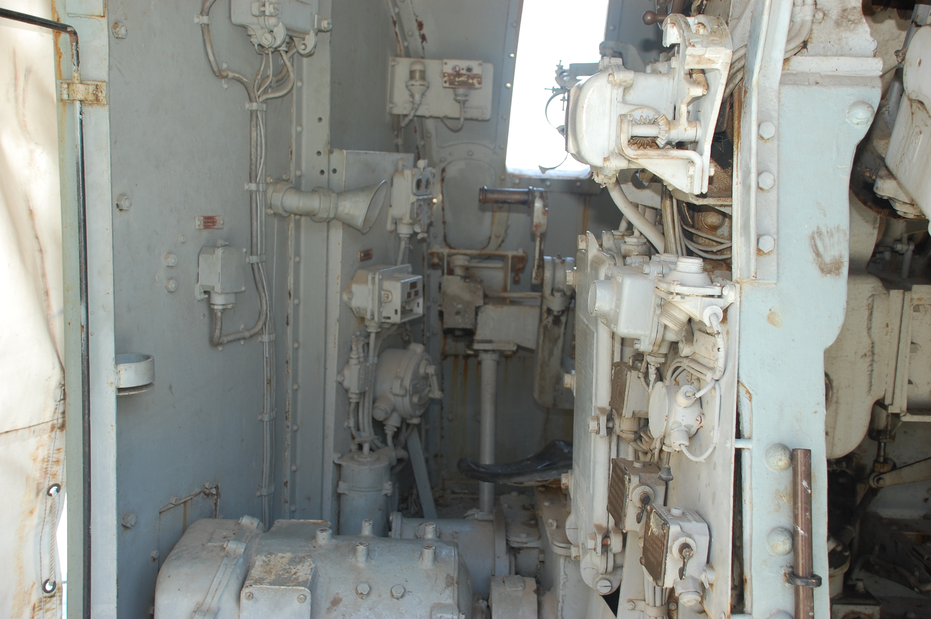 |
| Leftmost side of the 4 inch mount.(Photo by Jerry Proc) |
 |
| Left gun detail.,(Photo by Jerry Proc) |
CONTROLThe 4 inch gun was trained, elevated and fired electrically but was loaded manually. There was manual backup in case of power failure. Both barrels were driven by the same electric motor.
DUTIES OF THE 4 INCH GUN CREW
A 4 inch gun mount was staffed with a crew of 15 as indicated below. In addition, there were another 12 crew supplying ammunition to the guns. The number of men in the gun crew varied depending on what the ship was doing.
In normal operation, there were only four crew inside a mount. They were "riding" (inside) the mount. The Layer and Trainer were there as backups in case of a failure with the Mk 63 Fire Control System. Two Safety crew operated the interlocks that interrupted power to the firing buttons should a safety infraction occur. One such infraction would be to have a a loader standing directly behind the gun as the recoil force drove the breech some 18 inches backwards. The interlocks also energized the "Gun Ready" lamps on the bridge and in the Transmitting Station.
| LEFT GUN POSITION ' B' GUN | DUTIES | RIGHT GUN POSITION 'B' GUN | DUTIES | |
| Gun Layer | Elevates the gun barrels in manual mode and becomes the Aimer in power mode. He had an electric joy stick that trained and also elevated gun barrels. | Gun Trainer | Rotates the mount to the desired bearing. | |
| Communication/ Range Layer | He was also the Safety Officer | Breech Worker | ||
| Breech Worker / Captain of the Mount |
Fuze Machine Operator |
|||
| Fuze Machine Operator | Fuze Setter | |||
| Fuze Setter | Attaches the desired fuse to the projectile | Loaders: - 3 per barrel | ||
| Loaders: 3 per barrel | Places the shell into the breech | Ammunition supply | ||
| Ammunition Supply | Safety/Rake Number | |||
| Officer of the Quarters |
Note that the Crew Duty table above is applicable to the 'B' gun. only because it was the one which had the fuze setting machine. Years ago, Cmdr Bob Willson had the fuze setting machine moved from 'B' gun to the right barrel position on 'A' gun. This was dome so that visitors could see the fuze setting machine. As a result, there is no Fuze Machine Operator or Fuze Setter positions for the 'A' gun.
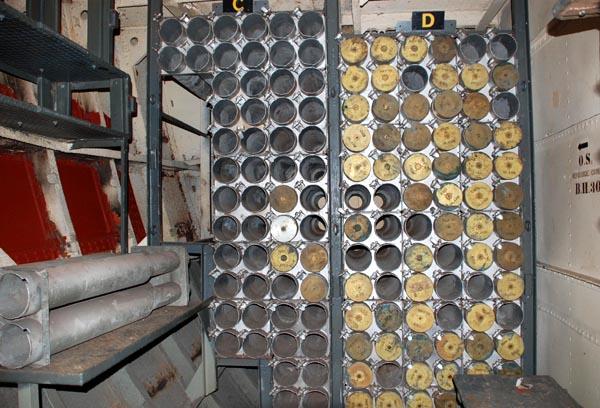 |
| This is one of two 4 inch magazines aboard the ship. 'A' magazine held 584 rounds while 'B' magazine held 537 rounds. The 4 inch guns could fire explosive shells or starshell. ( Photo by Jerry Proc) |
SHELL DATA and HANDLINGWeight of projectile: 35 pounds
Weight of Round:: 66 pounds
Muzzle velocity: 2,691 feet per second
Rate of fire: 15 rounds per minute (with fuses)
Recoil: 60 tons when the barrel was elevated to 45 degrees. (Recoil is the common term. "Deck Thrust" is the technical name for this force.
Detonator: Electric, not mechanical.Spent shells were extracted from the breech block by an extractor mechanism and flung unto the deck where they were kicked over the side. The crew who fed the guns obtained the rounds from the ready-use lockers. It was then left up to other crew to keep the ready-use lockers provisioned with rounds during action stations. There were four ready-use lockers for each 4 inch mount.
FUZES
There were three fuze types used with HAIDAs 4 inch guns.
* Direct Action Fuze. No setting necessary because it explodes on contact with the target.
* VT (Variable Time) type. Used to detonate Starshell . They were set for elapsed time after the shell leaves the gun barrel. Altitude is determined by the gun barrel elevation. It would be elevated for the desired range plus 1/2 mile or so. The intent was to illuminate the area behind the target.
Here is the way in which time is set.There is a small circular channel in the projectile head which is loaded with a powder that burns a fixed distance per second. To change the time of detonation, the fuze setter shortened or lengthened the distance from the ignition point to were it reached the charge. There were tables which related time to distance for the fuze. The Fuze Setter only rotates the nose of the shell. That in turn, changes the distance inside. In summary, the VT fuze explodes at a a predetermined distance above the ground rather than upon contact.
* Proximty Fuse - The fuze is set to detonate whenever the proectile comes close to a metallic object like an aircraft.
| This is a Mk 53 Proximity Fuse which used
three vacuum tubes. It is not known which Mark was used aboard HAIDA. The
vacuum tubes and associated electrical components in the fuze had to withstand
an acceleration of 20,000 Gs upon firing. To prevent premature
detonation and to give time for the fuze to clear the gun barrel, a simple
solution was implemented. The electrolyte for the battery was stored in
two separate but adjacent compartments. That made the fuze safe to handle.
Upon firing, the immense G force would break the electrolyte separator
and the battery would become activated once the electrolyte became mixed.
Once the battery was active, it took very little time for the
filaments in the vacuum tubes to heat up thus ensuring that the fuze was
far enough from the gun so as to avoid premature detonation of the fuze
Click on image to enlarge (Photo by Jerry Proc) |
FIRING TECHNIQUE
When firing at surface targets, HAIDAs gunners used a technique called straddling. When a salvo lands on either side or forward/aft of a target, this indicates that the fire control solution is correct and the next salvos may be fired without waiting for spot correction.
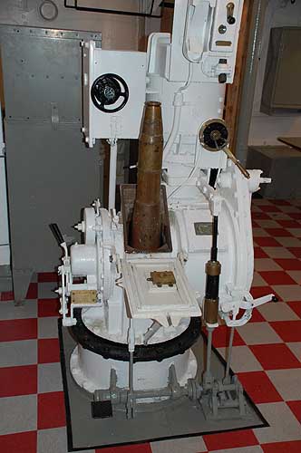 |
| This ammunition hoist has now been rigged by HAIDA volunteer Marg Mathers to illustrate a 4 inch round which has just emerged from the magazine. (Photo by Jerry Proc) |
 |
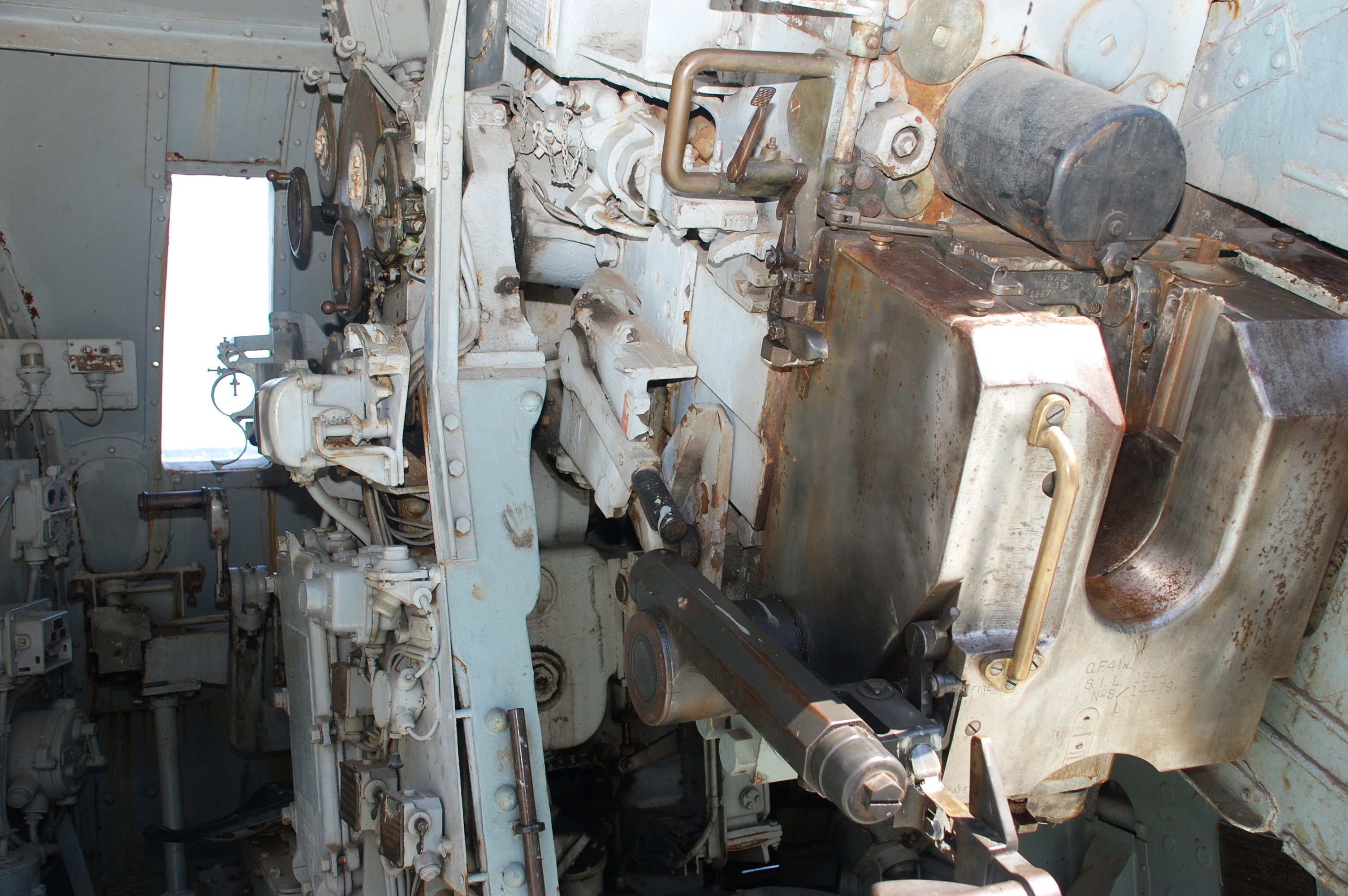
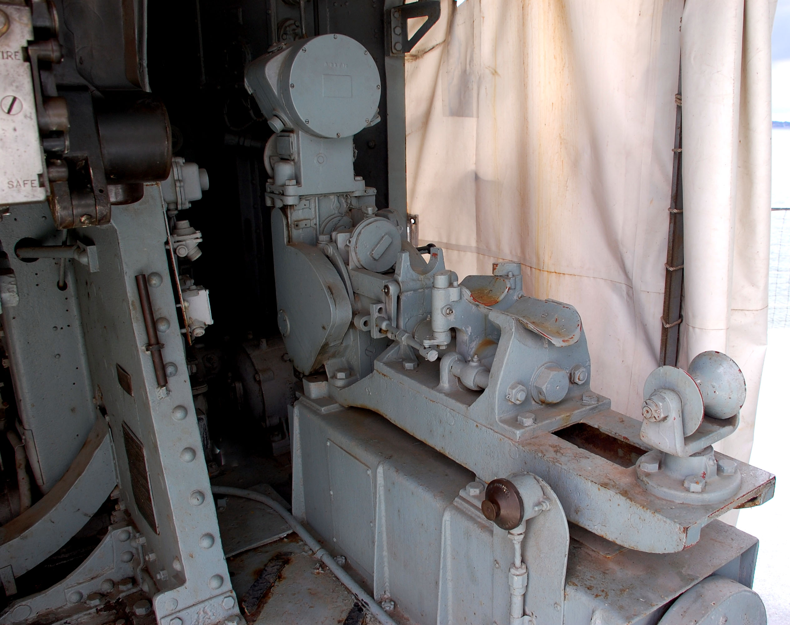
| An interior view of the 4 inch gun. At the right side is the fuze
setting mechanism with a practice round in the cradle. In use,
were three fuze types:
1) Proximity type. The fuze triggered when the projectile is near the target (ie aircraft) 2) Direct action 3) Timed fuze. (Photo by John Paszkat) |
 |
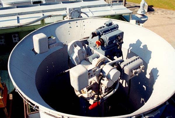
| A more detailed view of the fuze setter. This fuze setter was moved from the 'B' gun to the 'A' gun . Click on image to enlarge. (Photo by Jerry Proc) |
 |
| As part of modernization in 1950-52, HAIDA was fitted with a pair of Mark 29 gun sights. Illustrated above is the forward sight just aft of the bridge area. The other gun sight was fitted on the forward portion of the aft superstructure and controlled the 3" 50 gun. (Photo by Jerry Proc) |
An "aimer" stood in between the two counterweights and aimed at the target by using the two optical sights mounted at the top. The upper sight (black eye shroud) was used to acquire the target while the bottom one (orange eye shroud) was used for visual tracking. As the aimer tracked the target, this motion was transmitted electrically to the gun.In order to hit a target, the gun must be fired in advance of the target's current position. This calculation is called "leadoff". The lead angle was developed by three gyro's fitted within the sight housing. There was one gyro for each of three planes of motion. Radar (AN/SPG34) was used to determine the actual range of the target at any given moment in time. Once the target was acquired, the aimer would squeeze the lever in the red handle and "uncage" all three gyro's. Range information produced by the radar was fed in electrically and would control the distance that the gyros moved. The longer the distance, the further the gyros travelled thus developing the lead angle. The leadoff was also affected by the speed of the target and whether it was moving left to right or right to left. Rifling in the gun barrel imparts a spin to the projectile in order to keep it from tumbling end over end, however this spin also causes it to drift slightly to the left or right depending on the direction of the rifling. At the same time, gravity is pushing the projectile downwards. Hence, all these factors need to be taken into account when developing the leadoff angle.
The AN/SPG34 antenna affixed to the 'B' mount could control both 'A' and 'B' mounts simultaneously. The range difference, bearing and elevation were corrected by a parallax unit in the forward AN/SPG34 compartment.
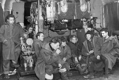 |
| Part of this 4 inch gun crew is definitely enjoying a lighter moment after some tough target practice. (HAIDA Archives Photo 991.074.001) |
 |
| Looking up, this is all that is left of HAIDA's WWII era 4 incch gun mount at the 'X" position. |
CONTRIBUTORS:1) Jim Brewer
2) Peter Dixon - Docent Manual 1994
Sept 23/24