ASDIC/SONAR  SYSTEMS  (1943 - 1963)

ASDIC is the original British name for the equipment which sent sound pulses  on specific bearings in order to detect submerged submarines. The acronym means Antisubmarine Detection Investigating Committee and whose origins began in 1918. SONAR is the American term used for the equipment to detect submarines and it got its name during WWII.  The acronym means SOund Navigation And Ranging.  Reference to ASDIC was still being used into the early 1960s. The year 1965 seems to be a watershed year in which the term SONAR became standard terminology thus generating other terms such as passive-sonar and active-sonar.  The terms ASDIC and SONAR will be used ere depending on  which is more  historically appropriate.

The main components of a WWII era SONAR/ASDIC system are:
1) Sound pulse generating and receiving equipment.
2) An underwater transducer or oscillator of some type.
3) A dome to house the transducer or oscillator.
4) Recording/control  equipment to indicate range, bearing and depth of the target.

Besides  detection, SONAR can then be used to control weapons like a depth charge launcher or Squid. The main searchlight beam was for long range detection of targets and was developed during WW1. The 'Q' attachment and type 147 ASDICs were secondary sets used for maintaining contact with deep diving submarines  and were  developed during WWII. The terms oscillator and transducer are used interchangeably here.  Oscillator is the British term; transducer is the American term. Although physically different, the oscillator or the transducer perform the same function and they are the components of the system which get immersed in sea water.

Listed below are the SONAR/ASDIC systems which were identified as being fitted to HAIDA.

NAME DESCRIPTION DISTANCE IN SERVICE DATE END DATE
144 ASDIC Main ASDIC set 2,500 yards 1943 195? 
1444 'Q' Attachment Secondary set 1,200 feet 1943 195?
147B Depth Finding Set.  Used in conjunction with 164B set 1,000 feet 1943 1963
AN/SQS-10 Scanning sonar.  6,000 yards 1952 1963
AN/SQS-501 (also called type 162)  Sea Bottom Identification set 1.800 feet 1952 (?) 1963
164B Range and Bearing Finding Set For Ahead Throwing Weapons like Squid 2,500 yards 195?  1963
AN/UQC-1B Underwater Telephone 8,000 to 12,000 yards 1960 1963
The in-service date for the 164B is problematic. According to the Imperial War Museum, the production years for the 164  set were 1956 and 1957. Assuming a best case procurement, that means that 164 was not aboard the ship until 1956 or possibly 1957. That leaves a gap in the SONAR chronology and also suggests that the 144Q may have stayed aboard ship until the 164 sonar was installed.

A 1952 drawing shows the SQS-10 repeater display in the Operations Room, so that confirms the in-service date for that SONAR type.
 

144 ASDIC (1943-1949)
144q_range recorder_b.jpg
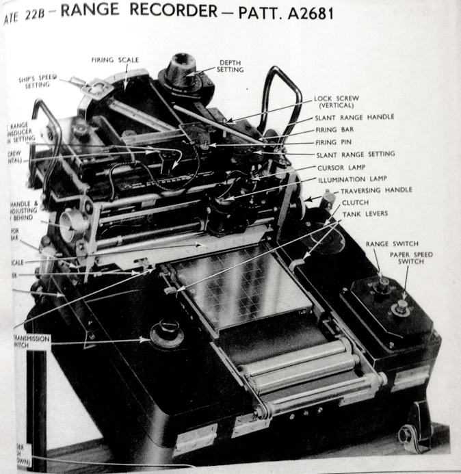
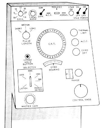
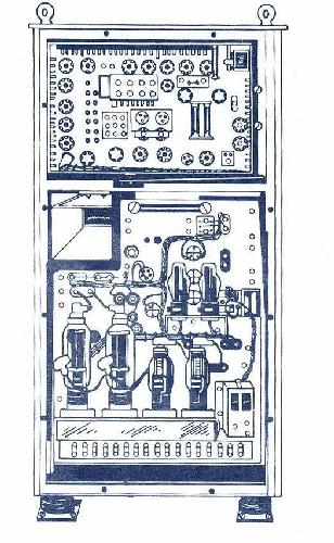
144 ASDIC range recorder. Click on image to enlarge (Collingwood  Heritage Collection)

To record echoes.specially treated paper was driven by a gear mechanism and marked with a stylus. This paper was impregnated with a solution of potassium iodide and starch. Passage of electrical current through the paper from stylus to roller released 'free' iodine. The iodine was then deposited on the paper thus making a record in the form of a brown mark. When installing fresh paper records, it was imperative to minimize the amount of time that the paper was exposed to air. Within the recorder, the paper roll was stored in an airtight container known as a tank. Each roll of paper was 30 yards long and a black warning mark would appear on the right hand edge signifying the approach of the end of the roll. After its appearance, there was still sufficient paper remaining to complete the attack. Alternately, yellow coloured, cadmium-iodide paper could be used in the range recorder. Generally speaking, the range recorder was only switched on when investigating a contact and during attack.

The recorder also had a paper speed switch which had two positions. - Cruising and Attacking. In Cruising , the paper moved slowly, just fast enough to give a clear space for the stylus to mark on. In Attacking mode,  the paper moved at a faster speed. The object of the switch was to save paper by providing a slow paper speed when sweeping. When sweeping was initiated, the range recorder operator had to see that the paper speed switch was set to cruising. On gaining contact, the switch was set to Attacking .

To summarize, the range recorder has two jobs. One is to make the transducer train and transmit when it should. The other is to mark the echoes on the paper and indicate the time to fire the A/S weapon. The recorder is fitted with control switches. They are the barrel switch with four positions, the scale change switch and the paper speed switch. It also has a handle to adjust the transmission interval.

asdic_sonar_144q_bearing_recorder_b.jpg
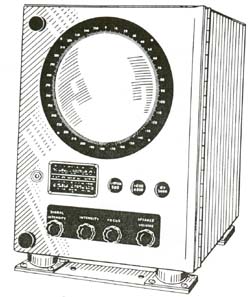
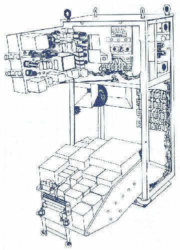
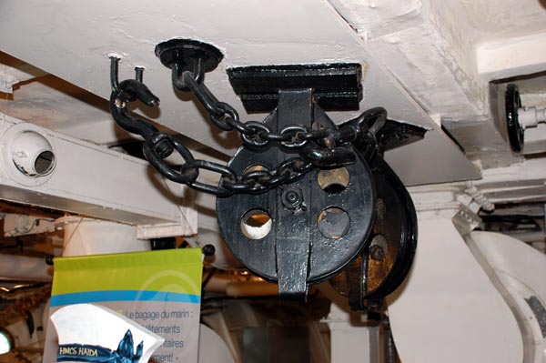
144 bearing recorder (Collingwood Heritage Collection)
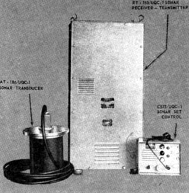
There is no photo available for the 144 transmitter or receiver equipment. Photos of the transducers are very hard to come by because ASDIC was very secret during WWII,.
144_control_panel3_v1.jpg
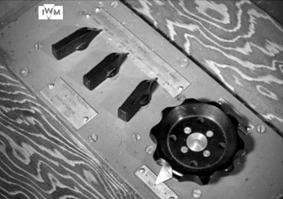
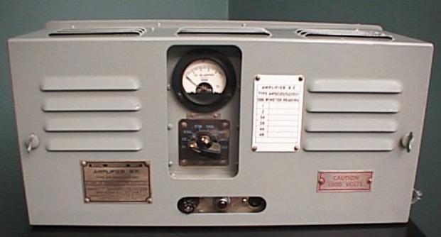
The Control Training Unit determines the movement of the oscillator. It can be swept continuously or in steps of 2.5 or 5 degrees. The direction of rotation cam also be set to be either left to right or right to left. It also contains the OFF/ON switch for the 144 system. Click on image to enlarge. (From an Imperial War Museum film) 
144_bearing_indicator.jpg
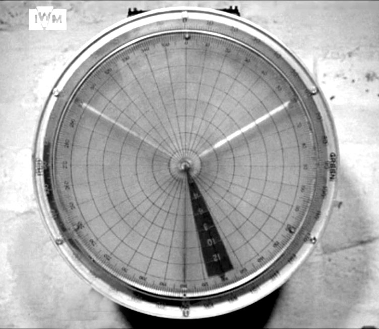
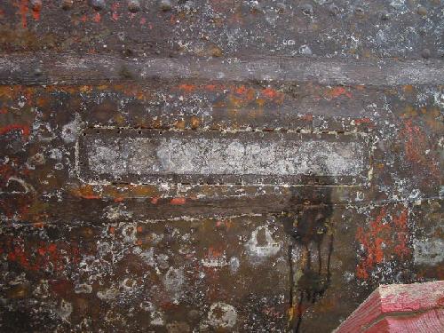
This bearing repeater unit shows the direction that the oscillator is trained to, (From an Imperial War Museum film) 
/144_echo_push_switch.jpg
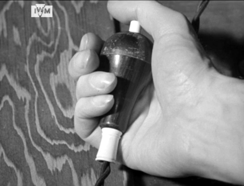
This is the hand held ECHO PUSH switch. It allows the operator to stop the  oscillator  from training once an echo is heard and the switch is pushed. (From an Imperial War Museum film) 
 
144'Q' ATTACHMENT (1943-1949)
No photo is available of the "Q" attachment
The 'Q' attachment was an additional ASDIC  set which required separate transmitting and receiving equipment suitably inter- connected with the main 144 set. Physically, the Q oscillator (transducer) was mounted beneath the main oscillator and trained with it. It projected a fan shaped beam that was narrower in the horizontal plane than the main ASDIC beam but sufficiently wide in the vertical plane to receive echoes at any angle from the horizontal to 45 degrees below horizontal. The beam was only 3 degrees wide on the horizontal plane. Collectively, ,it enabled contact to be maintained with deep targets at short ranges and also minimized the dead zone. The Q beam was transmitted through a window in the bottom fore part of the  ASDIC dome.

This arrangement also allowed the Q oscillator to be used at angles of up to 70 degrees from the bow. In shallow water, the Q beam would strike the bottom giving long drawn out echoes that appeared similar to heavy reverberations. This effect made the Q beam appear stronger than the main beam but the effect disappeared in deep water.

According to Norrie Millen (retired Royal Navy):

"I think under ideal conditions a range of 2800 to 3000 yards was possible with the 144 set , It all  depended  on sea state,  water temperature, water salinity  etc. Q and Q2 [attachments] were used for close range contacts"

In order to locate a submerged submarine, it was necessary to determine the range, the bearing and depth of the target .On-build, this was done with the 144Q and 147F ASDICS.  This graphic gives some indication of how the beams looked. (Source: DDE220.com)

 
MODEL  FREQUENCY  DESCRIPTION BEAM SHAPE RANGE  TRAINING 
144 MAIN  14 to 22 KHz 15 inch transducer held in a vertical plane.  Conical  2,500 yards All around in horizontal plane
144 Q  38.5 KHz Strip shaped  transducer - 12 inches by 1 inch Wedge shaped in horizontal plane  1,200 yards All around in horizontal plane
147 "SWORD" 50 KHz Strip shape  transducer  - 4-5 inches wide by 4-5 feet long.  Fan shaped in horizontal plane 1,000 yards Tilted 45 degrees backwards in a vertical plane. 
A film on the general operation of the 144 ASDIC can be found here. (Via Imperial War Museum)
147B "SWORD" DEPTH FINDING SET (1943-1963)
No 147F photo is available at this time
The 147 type was a depth finding set that complemented the main ASDIC  set (144Q ) and the Q attachment. It's most notable feature was its sword shaped oscillator operating at a frequency of 50 KHz. Physically, the sword was four to five inches wide and approximately four to five feet long. To prevent interference with the main set, the 147 was mounted ahead of it. When not in use, the sword was stored in a lifting tube mounted within the hull. 

When deployed, the sword could project a fan shaped beam being narrow in the vertical plane and wide in the horizontal plane. It could be trained up to 65 degrees horizontally and 45 degrees vertically .This new design, which added depth determining capability, could accurately track a target within 20 feet. Another feature was its integration with Squid, an ahead-throwing Anti-Submarine (A/S) mortar. But Squid was not fitted to HAIDA until her 1949 - 1952 modernization. 

When an echo was received on a 147B set, the operator would tilt the sword until the echo was lost. He would then reverse the procedure until the echo was heard again, then continue sweeping until the echo was lost on the opposite end of the sweep. Every echo received would then be printed on the depth recorder. A line of light on the depth recorder would indicate the centre of the echo trace. The operator would then look at a calibrated scale and read off the depth directly in feet. From here, the information was used for setting the pistols on depth charge fuzes. 

In 1942, the minimum range for a lost contact was around 170 yards, As U-boats went deeper when attacked, the minimum range was about 270 yards in 1945.


AN/SQS-10 SCANNING SONAR (1952? to 1963)
The AN/SQS-10 sonar was called an azimuth scanning AM type since it transmitted and received omni-directionally.  SQS-10 sonar was granted 'AN Nomenclature' type number in 1950 and manufactured by Sangamo Electric. Unlike the wartime ASDIC sets, this unit did not use a quartz oscillator. Instead, it used  a transducer -- a device that produces underwater sound based on the magnetostriction principle. Unlike the 2000 yard limit of the wartime ASDICS , this set could operate out to 6000 yards under ideal conditions when echo ranging.
asdic_sonar_sqs10_system_block_b.jpg
AN/SQS-10 block diagram. Click on image to enlarge. Transmitting and receiving equipment would have been located in the Sonar Equipment Compartment in the forward  mess deck.  The operator's console is in the upper left of the diagram. (Image courtesy Sangamo Electric Company)
asdic_sonar_sqs10cons.jpg
The  operator's control console was in the SONAR Control Room.. Targets were displayed on a Cathode Ray Tube. When HAIDA paid off, the RCN removed the console. (Graphic courtesy of the RCN)
/asdic_sonar_ip165_sqs10_1.jpg
The IP165/SQ was a slave indicator for the AN/SQS-10. It was mounted on an angle above the VK5 radar display Besides the indicator, there was a feed to the big plot table auxiliary projector so you could see the position of the submarine  track,  its course and speed. (Image courtesy RCN)


164B ATTACK SET ( 1952? to 1963)
This ASDIC set was mainly fitted into frigates and Tribal class destroyers and designed to be used with Hedgehog or Squid  weapons.. It incorporated a quartz transducer  In many ways, it was very similar to the 144 se. Type 164 was a range and bearing finding set that was supplemented with depth data from the 147F set.  For Tribal Class destroyers, Hull Outfit 7 (sonar dome)  or 7A was used. On HAIDA, both the 164 and SQS-10 transducers were fitted into Hull Outfit 7A. 
/asdic_sonar_164_range_recorder.jpg
Type 164B range recorder. Click on image to enlarge. (Collingwood Heritage Collection)
Type 164B bearing recorder Click on image to enlarge. (Collingwood Heritage. Collection) 

 
AN/SQS-501 BOTTOM FINDING SET (1952? - 1963)
The AN/SQS-501 was an auxiliary set designed specifically for identifying submarines lying on the ocean floor where the depth of water was not too great. It could also be used to determine the depth of water under the keel. 

There were three, fixed, quartz transducers mounted in the forward end of the ship's hull. One unit faced port and another faced starboard. The third unit, mounted in the keel, faced straight down. In operation, either the port and keel or the starboard and keel transducers were used. They produced a sound beam at right angles to the ship's fore and aft line. This beam was fan shaped, being narrow in the horizontal and very wide in the vertical plane. A simple changeover switch provided a means of projecting the beam to port or to starboard.

The recorder produced a shadow trace that gave a reasonably clear picture of the bottomed object. By application of a mathematical formula, it was possible to determine the length and width of the target. The transducers were mounted in hull fittings that were secured on the inside of the ship's hull. 

Another system equalized the pressure inside the fittings to that of outside sea water. This was accomplished with inter-connecting pipes between the hull mountings and a supply tank that was mounted inside the ship at water level. The liquid used in this system consisted of a mixture of water and glycerine. This prevented freezing and possible damage to the hull mountings in colder climates.

Otherwise known as "Tracer" (RCN) or "Sounder" (RN),   SQS-502 was functionally equivalent to  type 162 sonar. 

asdic_sonar_sys_sqs501_rfamp1.jpg
A/N SQS 501 amplifier. This was just part of the system.  (Photo courtesy of  jtaudio@shaw.ca)
/asdic_sonar_sys_sqs501_hull_opening.jpg
The three hull openings  for the SQS-501 transducers would have looked like this. This photo of HAIDA's hull was taken when she was in drydock in 2003. The hull has just been power washed, hence the visibility of hull pitting.  (Photo by Jim Brewer)


AN/UQC-1B UNDERWATER TELEPHONE (1960- 1963)
The AN/UQC-1B equipment is designed for use in submarines and surface ships tin order to provide voice or CW communication.

This device was an underwater communication set, or as it was more commonly referred to as an Underwater Telephone. It was designed for use in  submarines and surface ships to provide amplitude modulated (AM) voice or CW (Morse code) communication through the water using a 8.0875 kHz carrier. 

The AM mode employed Single Side Band (SSB) using the upper side band (USB). The useable range varied between  8,000 to 12,000 yards depending on ship's speed and sonar conditions. That is the range quoted for the 'A'  and 'B' variants.  Morse code used a fixed audio note of 712 Hz. Personnel stationed on the ship's bridge used a telephone like device when communicating on voice.

A small, cylindrical, magnetostriction transducer was fitted in the sonar dome, aft of the main set. A combined receiver-transmitter panel was fitted in the Sonar Equipment compartment while the 'sonar set  remote control unit (SSC-RCU) was mounted at either the command position on the bridge or in the operations room. The SSC- RCU contained a power off/on switch for the set, a loudspeaker with volume control, a Morse key, a phone/CW switch and a microphone. The UQC-1B gear was housed in the Sonar Equipment compartment which is on the forward mess deck. The transducer for the UQC-1B was located in the sonar dome. 

A hand written note on one of the source documents for this device indicates that the RCN ordered 45 sets on the initial procurement.  HMCS Haida was fitted with the AN/UQC-1B at the time she was paid off.

The in-service date for the fitting of UQC-1B in HAIDA is a bit uncertain. Here are the production dates for the variants.

UQC-1A - March 1958
UQC-1B - 1960
UQC-!D -  1962
A Parts Manual for the UQC-1B is dated 1956. Unless some collaborating data arrives, post 1960 will be used as the in-service date for the UQC-1B aboard HAIDA. 
 

/asdic_sonar_sys_uqc1_case.jpg
Not much to see on the exterior of the AN/UQC-1B. This example has certainly seen better days. .(Photo courtesy of Destroyer Escort Central web page http: //www.de220.com)
sdicsonar_sys_uqc1_parts_v2.jpg
These are the principal parts of the AN/UQC-1B system. From left to right: Transducer with cable, Receiver-transmitter cabinet and the control unit (Maritime Park Association)


asdic_sonar_sys_uqc1b.jpg asdic_sonar_sys_uqc1c.jpg
AN/UQC-1B: Front view of the receiver-transmitter cabinet with the service panel removed.  (Graphic courtesy of RCA Victor) AN/UQC-1B: The receiver-transmitter cabinet with both chassis swung down for servicing.  (Graphic courtesy of RCA Victor)

 
HULL OUTFITS 
The enclosure in which oscillators or transducers were fitted was called a hull outfit and more commonly called a sonar dome.
/asdic_sonar_sys_wwi
This is a cutaway view of a WWII era ASDIC dome  and approximates the placement of the main oscillator (transducer) for the 144Q ASDIC. It is not known if HAIDA's dome was identical in appearance.  (Image source unknown) 
asdic_sonar_sys_hull_outfit7.jpg
Hull outfit 7A. This SONAR dome, known  as “HULL OUTFIT #7A” was part of HAIDA’s SONAR system and would be found under the hull about one third the length of the ship. Three   transducers were mounted within the Hull Outfit.  The exterior of the Hull Outfit is clad with a special type of stainless steel called Staybrite. Normally, the dome is retracted when the ship is in shallow water or in harbour. When SONAR is to be used, the dome is lowered from its retracted position. It then floods with sea water, thus permitting the passage of the  transmitted sound pulse and reception of echoes. In the above photo, the hull outfit is being displayed in the inverted position. 

SONAR could not be used if the ship was travelling over 15 knots because the water flowing over the Hull Outfit would produce noise and mask the echoes.. (Photo by Jerry Proc)

asdic_sonar_sys_ hulloutfit7a-1.jpg
Cutaway view of Hull Outfit 7A showing the dome hoist. It approximates the placement of the transducers for the AN/SQS-10 and Type 164 SONARs and the AN/UQC-1B underwater telephone.    (http://www.hazegray.org/navhist/canada/systems/sonar/) 

 
sonar_dome_hoist. DSC_0038.JPG
The somar dome hoist was used to deploy or retract the sonar dome.
sonar dome hoist DSC_0037.JPG
If the ship was in drydock, and the sonar was in need of maintenance, the dockyard mateys  would drop the dome and work on it in that way. If the ship was  in the water and not accessible to a dry-dock,  then the crew would work on the transducers by going in from the top.  It is believed that the transducer for the AN/SQS-10 sonar weighed over 400 lbs.

When the dome was in the  up position there was a seal that allowed the inside cover of the dome to be removed without the ship filling full of water. That was one way of exchanging a bad transducer. 


/sonar_dome_hoist_accessory_DSC_0039.JPG
This winch could be used to lift the  sonar transducer element(s)  from the housing  It was used in conjunction with the heavy duty pulley to the right.  When it was necessary to swap a transducer,  it could be lifted up through holes in the mess decks above. These holes were in alignment with the winch. with the winch.

SONAR CONTROL ROOM


/sonar.jpg
HAIDA'S  Sonar Control Room as it appeared  in 2007. It  would have been staffed by four operators and  was located on the Flag Deck, port side, next to the Operations Room. (Photo by Jerry Proc) 
/scr_equipid1.jpg
Equipment n this photo:

1) Dome locator. It has  three indicator lights: up--moving--down.
2) Gyro repeater.
3) 164B Bearing Recorder. It also sent a signal to a readout in the wheel house. When the bridge gave the order "steer by sonar", the helmsman would follow the sonar bearing  repeater.
4) A/P 9960  Control Trainer. By turning the knob to a new bearing,  the transducer will follow to the new bearing. By pressing the knob, the sonar set transmits a single pulse. This is also known as the Captain's Bearing Instrument. 
5) 164B Range Recorder.
6) 164B Down Angle Recorder. 
7) Barometer. It does not belong in the SCR and was placed there only to cover up a bunch of cut cable ends. 

Three, small, circular gauges mounted to the plywood bulkhead do not belong there. These are pressure gauges and were  mounted for a movie shoot. They have never been taken down.

The AN/SQS-10 operator's console would have been at the aft bulkhead of the Sonar Control Room. It was removed from the ship by the Navy when HAIDA paid off.  There was also a repeater for it above the VK5 PPI in the Operations Room. 

Out  of view is the AN/SQS-501 recorder which was mounted on the starboard bulkhead in the Operations Room.

To hear pinging from a real sonar, select this link  (168 kb wav file). What you are hearing consists of a transmission, followed by an echo after 3 seconds. This is repeated a second time. It therefore takes 1.5 seconds for the sound to reach the target. The returning echo after 3 seconds corresponds to a contact approximately 2,400 yards away (Calculation: The speed of sound in water is approximately 4,800 feet per second  multiplied by 1.5 seconds = 7,200 feet or 2,400 yards). File courtesy of Keith Wilbur.

One of the four sound systems fitted in the ship was in the Sonar Control Room. It was the Admiralty Pattern  AP 12523 type 366 and located next to the power supply for the VK5 radar repeater.


Contributors or Credits:

1) https://acoustics.ac.uk/wp-content/uploads/2018/08/D1_WHackmann_History.pdf
2) Sonarman Trade Group 1 Manual. RCN. 1963
3) http://www.hazegray.org/navhist/canada/systems/sonar/
4) Jim Brewer <snack.235(at) sympatico.ca
5) http://rnsubs.co.uk/articles/development/sonar.html

  Jan 15/21