INTRODUCTION
HAIDA's electrical system consists of the elements listed below. It is important to note that a generator produces Direct Current (DC) power while an alternator produces Alternating Current (AC). The prefix "turbo" means that the prime mover is a stream-driven turbine. To be correct to HAIDA's years of service (1943-1963), the term cps (cycles per second) is used versus the term Hertz (Hz) which started coming into usage in the mid 1960's.TURBO-GENERATORS
Two, 200 kilowatt turbo-generators produced 225 volts of Direct Current. This power was distributed from the generators to the main switchboard located in the Low Power Room (mid-ships) and the aft switchboard in the Gearing Room. These two switchboards are inter-connected so that power could still be supplied throughout the ship even if a portion of the system was damaged. All of the lighting and any motor driven equipment such as ventilation fans or pumps ran from 225 volt power. The switchboard also permitted the ship's electrical load to be transferred from ship's own power to shore power when berthed.
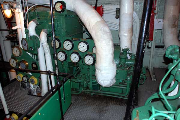 |
| Starboard turbo generator - front view |
 |
| Turbo generator - end view #1 |
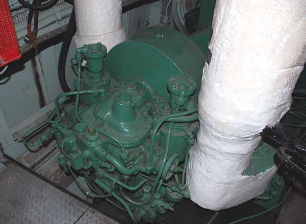 |
| Turbo generator - end view #2. |
DIESEL GENERATORSWhen shore power was not available, internal power could be produced from either of two auxiliary 60 kw diesel generators. These were originally Paxman 6 cylinder units last built in 1952 but fitted on all the Tribals built in the UK. Later on, the Paxman units were replaced with 100 kw diesel generators likely during the 1949/52 refit. Each 100 kw, 225 volt DC generator is powered by a three cyliner General Motors (Model 3-268) diesel engine. The forward generator is fitted in Boiler room #1 while the aft one was in the aft portion of the Gearing Room. The aft generator has been restored to functional order by Stoker Marg Mathers and is still capable of providing power to the ship.
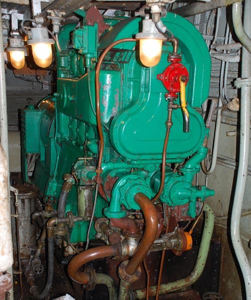 |
| Front view of the GM 3-268 diesel generator. The generator itself is at the back of the engine. |
 |
| This is the "business" end of the diesel generator. |
SWITCHBOARDSThe forward switch board is supplied by one 200 Kw generator fused at 900 amps and one 100 KW generator fused at 300 amps. There is a tie disconnect in the middle of the board rated at 1000 amps and two interconnecting disconnects are rated at 600 amps each. The after board is supplied by the other two generators with the same switching capabilities and capacities.
The aft switchboard identifies circuits starting from the letter A onwards while the forward board appends the number 1 after each letter. Example A circuit on the forward board would be designated 'B1' but on the after board, it would be just be a 'B. All major equipment such as weapons are fed from both boards through an automatic change over switch at each unit in case the power source fails The interesting thing is that the designators are not in direct correspondence with each other. As an example a power feed to a weapon could be from the forward feed and designated 'C1' while the aft feed might be designated 'K'.
 |
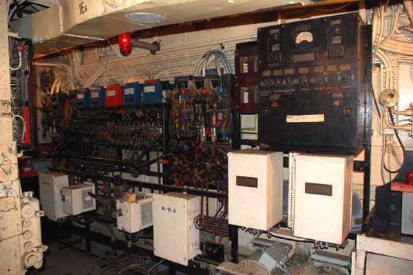
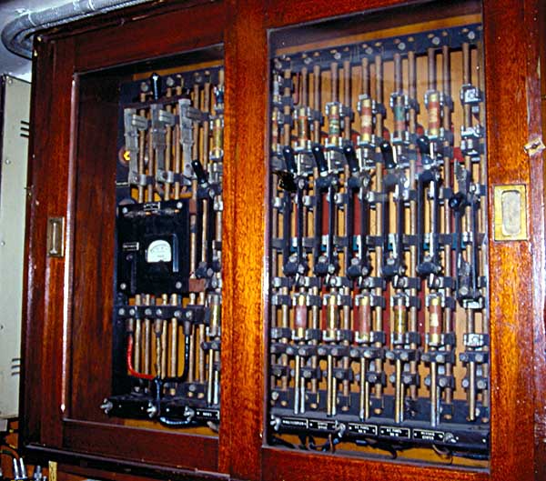
| Main switchboard - Looking at the aft bulkhead of the Low Power compartment towards starboard. Due to safety considerations, this compartment cannot be opened up to the visiting public since the switchboard in this compartment is "live". |
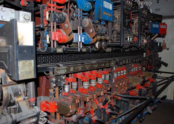 |
| Aft switchboard looking towards port. It was located in its own compartment within the Gearing Room. Due to safety considerations, the Gearing Room is not open to the public. |
 |
| Aft switchboard looking towards starboard. |
LOW POWER SYSTEMThe Secondary or "low-power" system is a 24 (nominal) volt D.C. system which is used to operate equipment such as gyro repeaters, plot tables and in an emergency, some of the radio equipment. When running, the system measures at 22 volts.
There was also a battery bank - 250 amp hours and normally one LP M/G and battery bank were run in parallel with trickle charge being applied. Also, there were two types of LP circuits - two wire for such things as M-type transmitters, FC motors etc and earth return for such things as gunnery firing circuits.
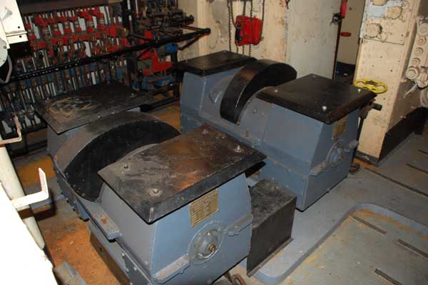 |
| A pair of 24 volt DC motor generators form the core of the Low Power system. |
 |
| Forward bulkhead of the Low Power compartment looking towards port. |
AC SYSTEMAs more and more North American electronics was fitted in the ship, there became a need to produce alternating current in large quantity. To facilitate this, two 50 kilowatt motor-alternators (M-As) were installed. One is located aft, adjacent to Radio 2 in the aft KVA compartment. The forward KVA compartment is located below the After-Lower Mess deck. These M-As produce 440 volt, 3 phase (delta), 60 cps AC power and each is rated at 50 kilo-volt-amps (KVA) . Examples of loads requiring 3 phase power include the 3in 50 gun mount and the sonar equipment.. The motor for the AN/SPS6-C radar antenna requires a 440 VAC, single phase feed. The 440 volt output is stepped down to 120 volts three phase using a 440/120 delta-delta transformer in order to power the bulk of the electronic equipment aboard ship. There is no neutral conductor in the system.
The forward M-A set has it stepdown transformer beside the control panel in the Electrical Workshop while the aft unit has its transformer behind the control panel next to the set. These alternators are driven with a 75 horsepower , 220 volt motor.
 |
| This is the restored aft KVA compartment. Note the ventilation (3L) shroud surrounding the motor-alternator set. The deck was restored in 2009 and the remainder of the compartment restored in 2010. |
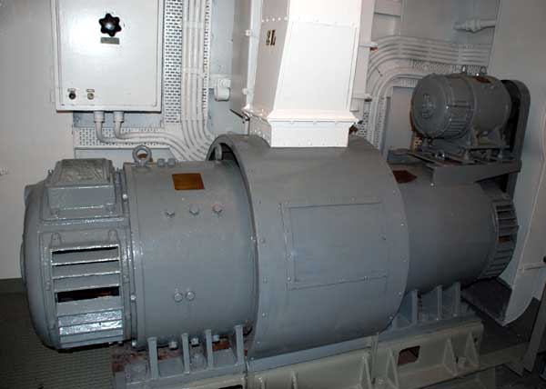 |
| Full view of the 50 KVA motor-alternator. The motor is on the left and the alternator on the right. The device atop the alternator is known as an exciter. It a small DC generator to supply the power that creates a magnetic field in the alternator. By varying the current provided by the exciter, the output voltage could be controlled. Frequency is controlled by varying the speed of the drive motor. |
DIESEL GENERATOR STARTING BATTERIESEach of the General Motors 3-268 two diesel-generators also need a 60 volt cranking battery. When the ship was in service, this battery consisted of ten, 6 volt batteries wired in series. Today, the battery for the aft restored diesel consists of five, series-wired, 12 volt, 950 (cranking) amp truck batteries. Due to overcharging but someone who didn't know what they were doing, these batteries were destroyed so the engine can no longer be started up.
 |
| This is the 3-268 starting battery for the aft diesel generator. |
*120 VAC 400 CPS SOURCEAlso fitted were two 120 volt 400 Hertz motor alternators which supplied power to parts of the weapons system, plot table system and the gyro compass. These were located in the forward "KVA" compartment area.
* 200 VAC 1100 CPS SOURCE was applied to the servo amplifiers fitted to the starboard side of the Transmitting Station.
* 50V 50CPS for indicator magslips.
* 120V 333cps (motor-alternator) for the gyro roll units in the Squid and gunnery systems.
* 20v 1100cps for power magslips.
OTHER PARTS OF HAIDA's ELECTRICAL SYSTEM
In 2019, the ship's electrical system was modified so that all lighting could be controlled by a single switch .This modification resulted in the loss of all power to Radio 2 and 3. .
 |
| This is the distribution panel for Radio 1 and 3 and is situated in Radio 1. Radio 2 used to get its feed from the aft 120 system while Radio 4 is fed from the transformer in the radar equipment space. ll switches in this panel have been left in the open position to compensate for the modifications done to HAIDA's electrical system. |
 |
| This small switchboard distributed emergency 12 VDC power to various pieces of gear in Radio 1. It obtained its feed from a bank of batteries located in a sealed enclosure on the other side of the bulkhead. |
 |
| Located in strategic positions, these heavy duty binding posts would be used to bypass a damaged compartment by providing an electrical feed to undamaged sections of the distribution bus. The bypass cables, which are terminated with huge lugs, were hung in the vicinity of the binding posts. Both the positive and negative 220 VDC lines have their own binding posts. |
 |
| Small electrical repairs were carried out in the Electrical Workshop located adjacent to the forward electrical switchboard. |
MESSDECK LIGHTINGPat Barnhouse of Ottawa Ontario took the effort to document his experiences as HAIDA'S Electrical officer. "Sometime during my tenure as the Electrical Officer of HMCS HAIDA between December 1959 and June 1960, the messdeck lighting was changed from DC-supplied incandescent bulbs to AC-supplied fluorescent lights. I believe this was done in just the four main messdecks - forward and after, upper and lower although it could have been extended to some of the others. This was not an authorized alteration for the Tribals, rather it was a unique, unauthorized fit in HAIDA only.
Impetus for this change came from two factors : a fleet-wide paint removal/cleanup campaign and a shortage of jetty DC shore power. The paint removal initiative came from the CANCOMFLT of the time, Commodore Plomer, who wanted the layers of paint removed from the interior of older ships for two reasons - reduction of a considerable amount of unneccesary weight that affected ships' performance and improvement in the interior appearance and cleanliness of the ships. The shortage of shore power was sorely felt on most occasions by HAIDA since being the junior ship in the squadron (a function of the Captain's seniority vis-a-vis the other Captains in the squadron), she always occupied the outboard position in the 'trot'. Jetties in Halifax were short of DC shore power and it was first come, first served. This meant, that almost all times alongside in Halifax, HAIDA had to run the diesel generator (which implied the services of a Stoker as watchkeeper) to provide sufficient power for domestics.
All the Halifax jetties had been supplied with ample AC power to support the St. Laurent and follow-on classes that were just coming into service. HAIDA, along with the other Tribals, had two large AC machines on board. These AC generators, usually driven by DC primary power, supplied power mainly for the 3inch50 gun and associated fire control system. Fortuitously, the Tribals were also supplied with an AC shore connection, no doubt to allow testing of the systems while alongside.
Since I had been put in charge, of the paint removal and freshup of the ship's interior, I had involved the electrical department in the endeavour. It was my Chief Electrician who suggested that we kill two birds with one stone by rewiring the messdecks for AC lighting, thereby making them even brighter since the DC incandescent bulbs didn't give a very good light at the best of times using readily available shore power. I gave the Chief permission to get on with it which he did by acquiring all the required bits and pieces (including light fixtures and a considerable amount of cabtire wiring) from naval stores and subsequently carrying out the complete installation.I did get caught in this unauthorized refit. Commodore Plomer came aboard to evaluate progress in his paint cleanup. The Captain proudly showed him our paint work and pointed out how "his" new fluorescent lights added to the attractiveness. Accompanying the Commodore was his Electrical Staff Officer, Commander Bev Miles who inquired of me, the refit number. I mumbled something about it being a "HAIDA special". He did not seem satisfied, but said nothing further. From that day, I never heard another thing about it!"
Additional Contributors or Credits:1) Jim Brewer <snack.235(at)sympatico.ca>
May 16/24