 |
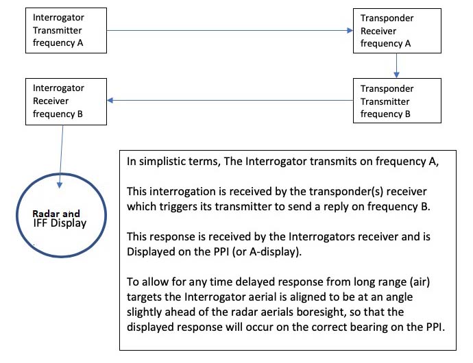
In order to best explain what IFF does, it would be prudent to understand some IFF basics.IFF is an acronym derived from the words Identification, Friend or Foe, a system which distinguishes friends from foe. To simplify the explanation, when IFF is being used, the interrogating radar automatically sends a series of coded pulses at the target. If the target is friendly, its transponder will reply to the challenge with a coded series of pulses. If the interrogator receives the correct code, then the interrogator knows that the target is friendly. The transponder was sometime referred to as a responsor unit in Royal Navy parlance.
Initially. IFF systems, had their own separate antennas mounted separately from the main radar antenna. In later developments , the IFF antenna was mounted in the "throat" of the search radar antenna. Mark XII IFF is the system currently in use today. HAIDA had the British Mark III technology installed on-build and later upgraded to Mark X standards. British IFF systems were designated into two series during World War II. The 240 designation was used for interrogators and the 250 series for transponders. IFF, in its most basic form, can be illustrated with the following diagram created by John Wise. To improve security, IFF systems were later re-designed to encrypt and decrypt the daily challenge/response codes.
|
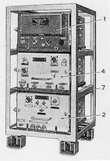
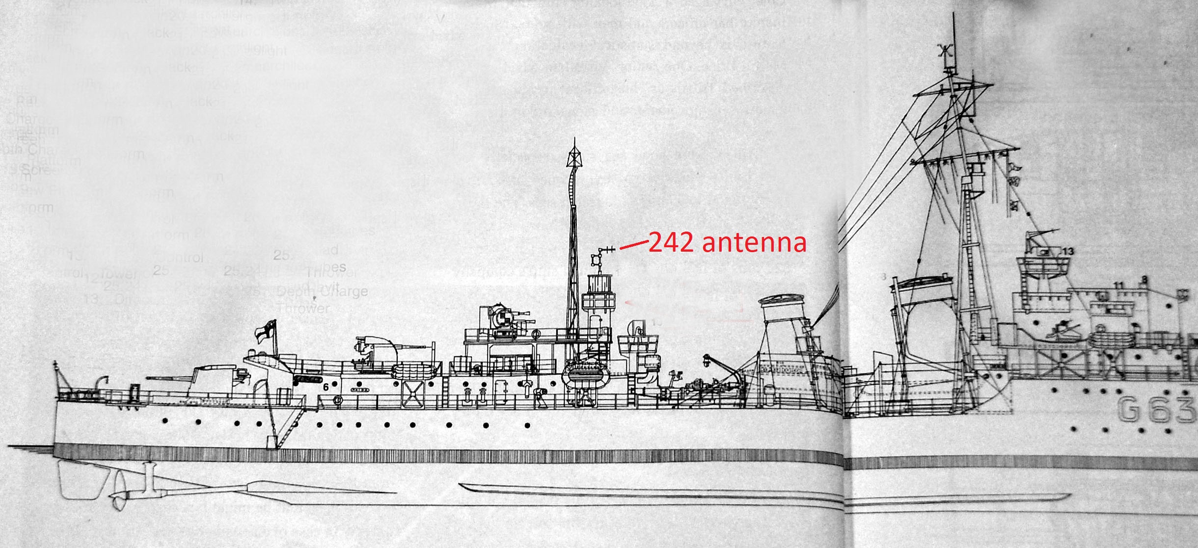
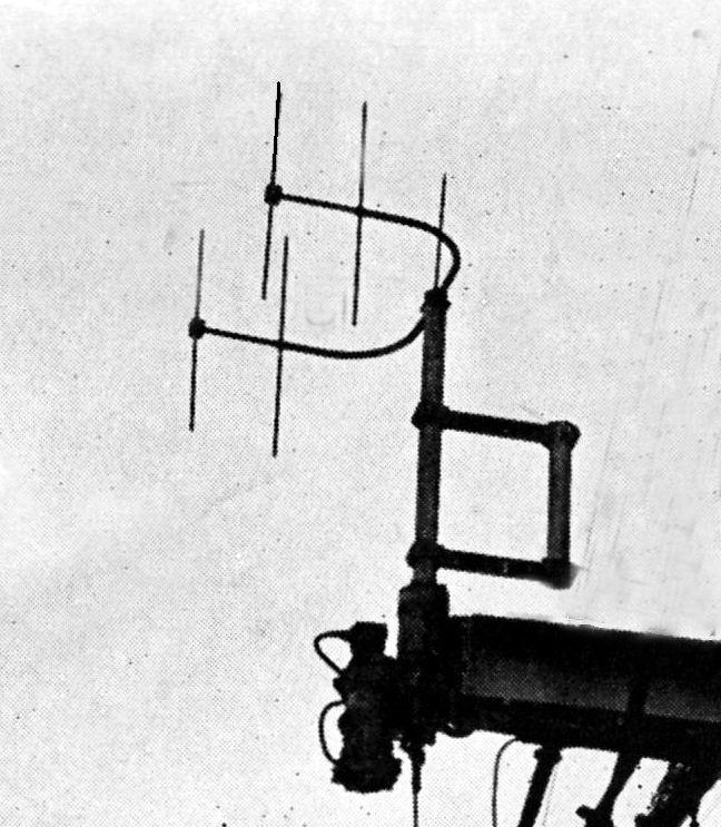
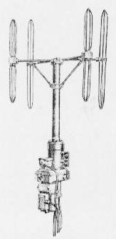
Type 242M Interrogator 1943 -1953 The Mk III ttype 242 interrogation equipment was fitted on RCN ships. A later variant, namely the 242Q, allowed the transmitter power to be selectable between 2 kw or 10 kw and the output frequency could be varied across a 30 MHz wide band. Type 242 equipment. It could operate in the 165 to 185 MHz band, but were normally used around 179 or 182 MHz. Power output was 1 kilowatt (British Admiralty) Location of the mating 242 IFF antenna atop the 271 radar enclosure. (Drawing via Battle Ensign Flying) Closeup view of the 242 antenna used with the 271 radar. The 271 radar was de-installed in April 1944 and was replaced with type 291 radar. (Image Royal Navy)
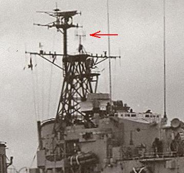
\ Aerial outfit ASS was used in conjunction with radar type 293 and the 242M interrogator. This is Aerial Outfit ASS as seen on HAIDA on her first tour of duty in Korea. (Photo courtesy RCN) Closer view of antenna outfit ASS. (Royal Navy)
Type 253P Transponder 1943 -1953(?) Type 253P was a shipborne transponder, compatible with the Mark III IFF system and operated in response to triggering pulses from any interrogator or radar set in the same frequency band. To limit mutual interference, the antenna for type 253P was situated at least 12 feet or more from the nearest interrogator antenna on a ship. HAIDA was fitted with the type 253P transponder. Type 253P equipment. (British Admiralty) It is presumed that when the AN/SPS-6C radar was installed, the British made Mk III IFF equipment was replaced with the Mk X, American made IFF equipment. The SPS-6C had the IFF dipole mounted in the feedhorn throat of the search antenna.
AN/UPX-1A IFF SYSTEM. 1953 to 1963 The Mk X IFF system sends a pulsed secondary signal from its Interrogator along with the main radar signal. This in turn is received by a Transponder situated in the target under observation. The Transponder then sends back an appropriate reply that is detected by the Interrogator and distributed for display. Separate pre-set frequencies are used for interrogation and reply - 1030 MHz for transmission and 1090 MHz for reply. Normally, the IFF antenna will rotate in synchronism with the main air warning radar thus enabling the responses to be superimposed on the radar display. HAIDA was fitted with the UPX-1 directional IFF and UPX-5 omni directional IFF.
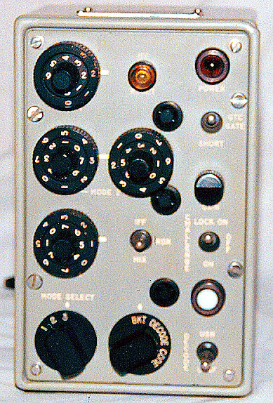
The UPX-1/ C1008 was the control box for the group video decoder. It controlled the mode of transmission ( ie mode 1, 2 or 3) and the 'squawk' code assigned to each particular ship. (Photo by Jerry Proc) When HAIDA paid off, this was her IFF fitting. It includes both UPX-1 and UPX-5 IFF systems. Unless otherwise noted, all this equipment was fitted into several racks in the Electronics Maintenance Room except for the IFF antennas. AN/UPX-1 SYSTEM
* AN/UPA-24 /KY80 IFF Video Decoder
* AN/UPA-24 /C1008 Radar Set Control (in Operations Room)* AN/UPX-1A /RT-194A IFF Receiver-Transmitter (for IFF dipole in front of SPS-6C feed horn)
* AN/UPX-1A /KY-61A IFF Coder/Decoder
* AB-274 IFF Dipole antenna assembly in front of SPS-6C feed hornAN/UPX-5 SYSTEM
* AN/UPX-5 /RT-269 IFF Receiver-Transmitter (for the omnidirectional IFF antenna on foremast yardarm)
* AN/UPX-5 /KY-88 IFF Decoder
* AS-177 Antenna Assembly (dedicated to UPX-5). 1090 mHz TX/ 1030RXMISC
These devices were shown on the ship's drawing but were never installed:
* AN/UPM-99 Radar Test Set
* AN/UPA-38 /KY-136 Video Coder
* AN/UPA-38 /C1407 Radar Set Control in Ops Room
 |
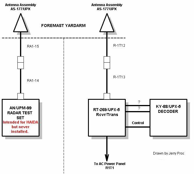
| One AS-177 antenna was for the omni-directional IFF, namely the UPX-5A system. The other AS-177 was for the radar test set. These IFF antennas were mounted at the very tips of the upper yardarm of the foremast. Because one of the antennas was deinstalled, when HAIDA paid off, its existing partner has been cloned and applied to the correct position on the starboard side of the yardarm. The UPM-99 set was specified on the IFF system drawing but never installed. In case the transponder coax cable became damaged, the coax for the test set could be pressed into service. (Photo by Jerry Proc). |
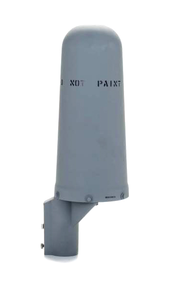 |
| The AS-177 omni directional antenna Here it is shown with its weatherproof enclosure. |
 |
| Above and below: Internal views of the AS-177 IFF antenna. (Images via E-bay.com) |
 |
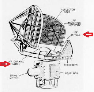 |
| This graphic illustrates the placement of the IFF interrogator dipole antenna in the throat of the main search radar. The dipole was fed by a separate cable. |
 |
| HAIDA's directional UPX-1 IFF system circa 1962. |
 |
|
|
| Except for a pair of AS-177antennas, all the IFF equipment was removed when HAIDA paid off. |
 |
| RT-269/UPX-5 receiver transmitter. Click on image to enlarge. (Photo by Serge.Margoulies) |
 |
| KY-88/UPX-5 decoder. Click on image to enlarge. (Photo by Serge.Margoulies) |
 |
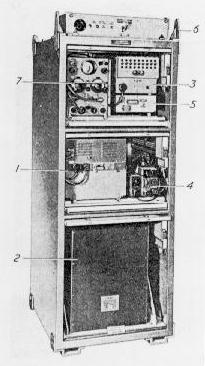
| This AC distribution panel, located
in the EMR, provided primary power to all the IFF equipment in the EMR.
Click on image to enlarge.Visible here (clockwise). are the circuit breakers
for:
1) UPA-24 Video decoder
|
Back to Tour Intro March 24/25