Mounted midships, is a quadruple mounting for 21 inch, Mark 9 torpedoes. The ship only carried 4 torpedoes in the tubes and reloading was not possible at sea since it was a difficult procedure. Torpedoes were fired from aft to forward to take into account the forward movement of the ship and to prevent them from colliding with one another as they left the tube. The torpedoes were the only weapons system to survive the entire life of the ship from 1943 to 1963.
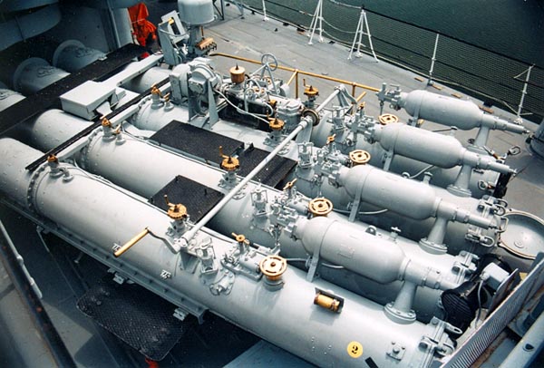 |
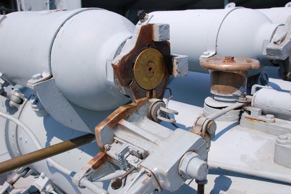
| The tubes can no longer be rotated electrically due to a shorted winding in the drive motor.(Photo by Jerry Proc) |
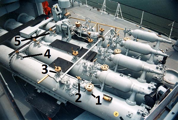 |
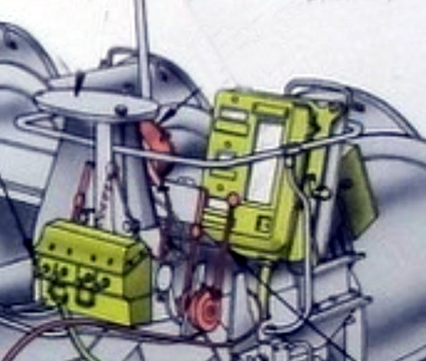
| Torpedo controls. Each item is in multiple of 4's except the crank
handle which rotates the mount manually and straddles all four tubes.
1 - Round brass wheel - Gyro platform set.
|
 |
| Click on image to enlarge.
4 - Unknown 5 - Locking pin 6 - Electric motor starter and control to rotate the mount. 7 - The small hand wheel atop the controller rotates the mount, 8 - Local operator's seat. 9 - Direction control. This is the clutch from the motor that determines the direction that the tubes turn. The further that the wheel is turned to the left or right, the faster the mount turns in that direction. 10 - Manual training crank. In case the mount lost electrical power, it could be manually rotated with the crank handle. |
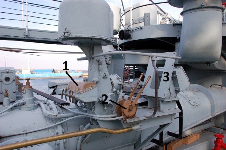 |
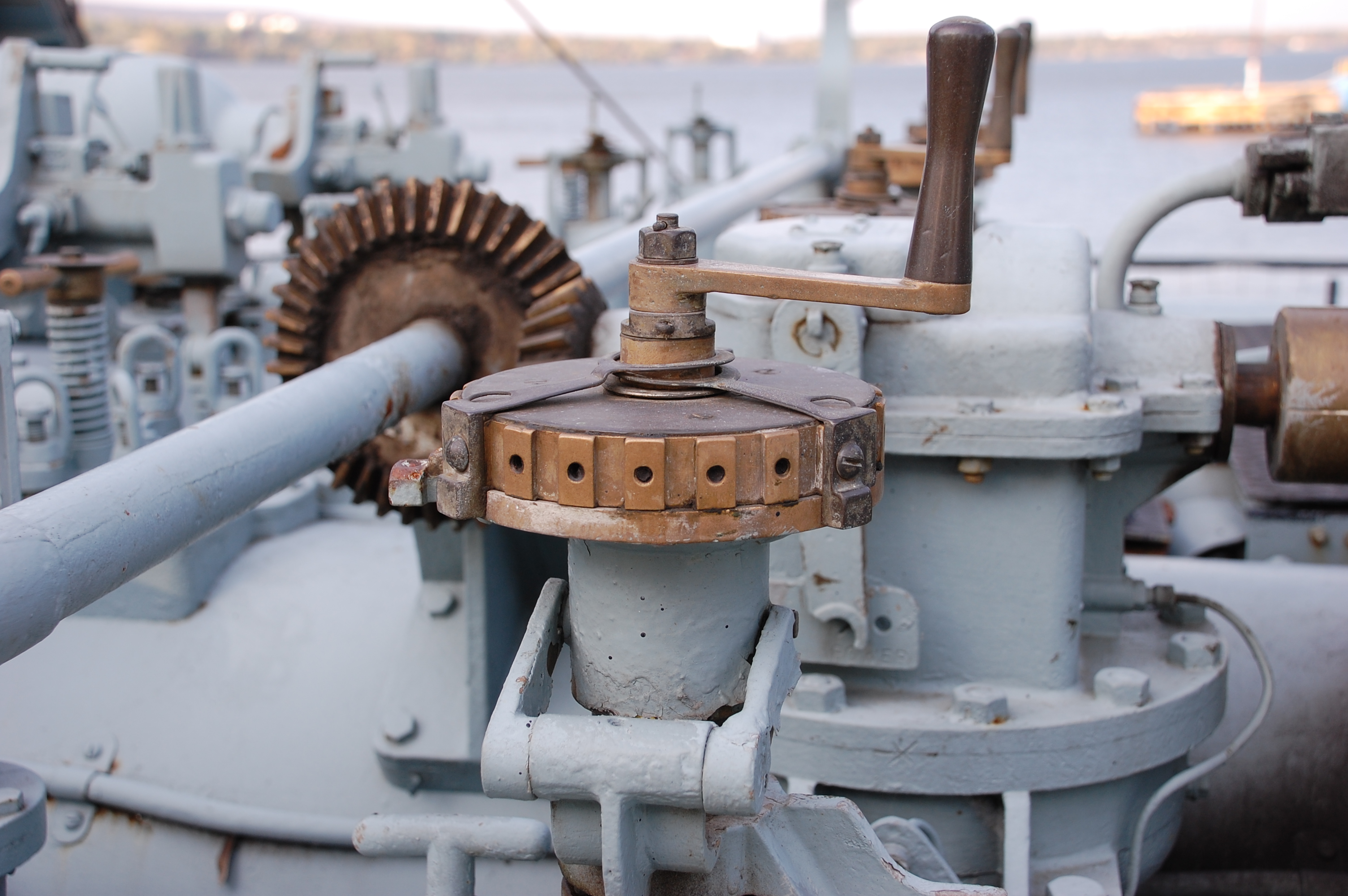
| More torpedo controls. If the bridge was put out of action, torpedoes
could be fired from this local position. Normally, the tubes were rotated
by an electric motor but if power was knocked out, the mount could be rotated
by a large hand crank. Inside the weatherproof dome is the torpedo
aiming sight. (Photo by Jerry Proc)
1) Transfer switch. This allowed the torpedoes to be controlled manually
from this position or controlled electrically from the bridge.
|
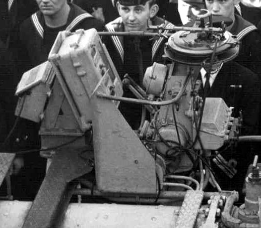 |
| The Order Instrument view of item #3. The person at the local position would have been a junior officer or a Chief or a P1 TGM (From Unlucky Lady) |
 |
| This is an Order Instrument which was fitted to the MK 8 torpedo mount. It looks identical to the instrument in the Athabaskan photo above. It is believed that the Order Instrument provided instructions on, range, number of torpedoes to be fired, gyro settings etc to the local torpedoman sitting on HAIDAs Mk 9 torpedo mount. |
 |
 |
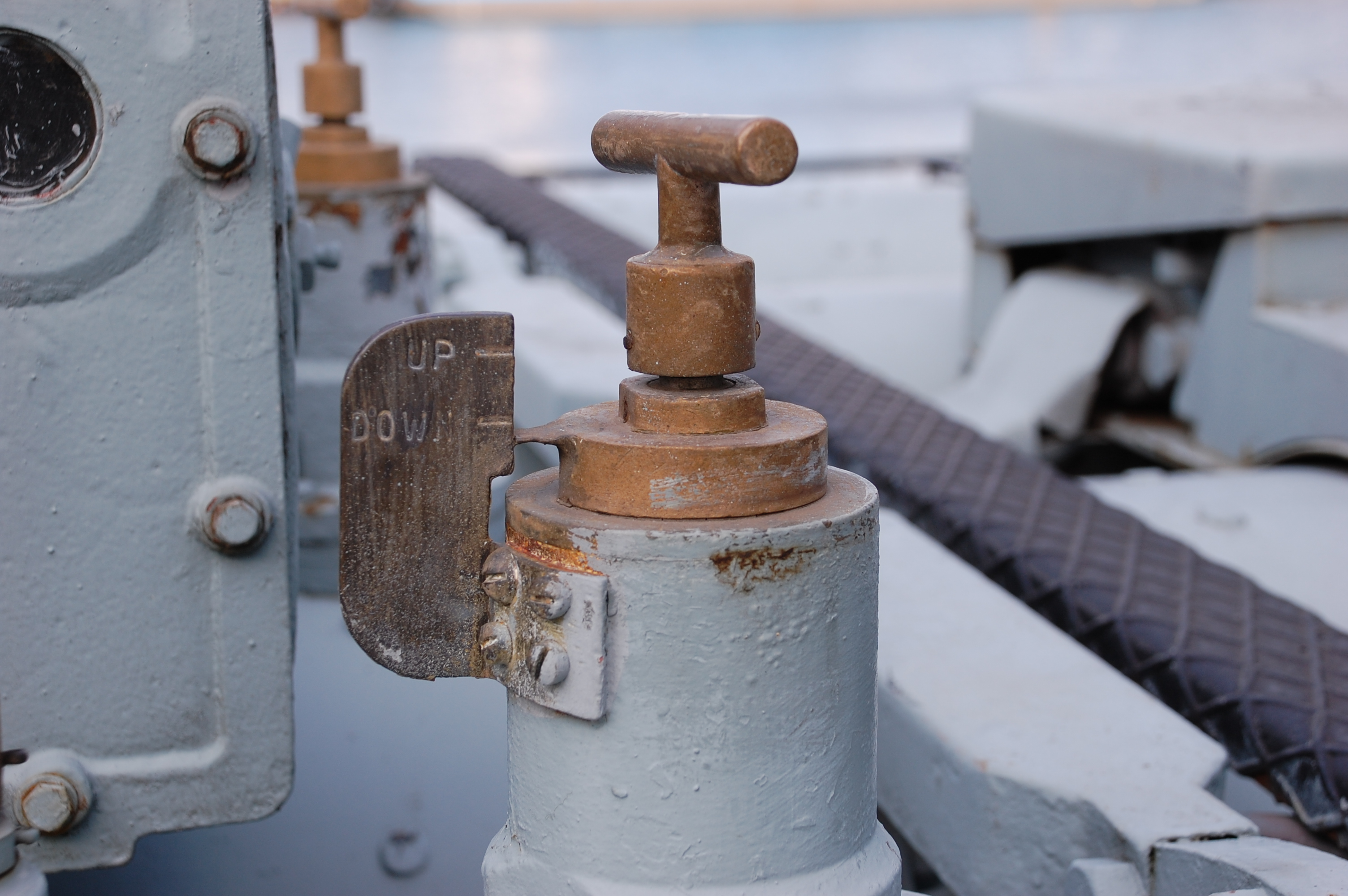
| Closeup of the locking pin, typical in four places. In the DOWN position, it would prevent the torpedo from leaving the tube if fired accidentally It needs of course, to be in the UP position in order to fire a torpedo.. | This is the control which determines the running depth of the torpedo. Typical for each tube. |
 |
|
| Click on image to enlarge.
Item 11 - Oil reservoir for the gearbox.
During peacetime, and in HAIDA's era, torpedoes were unarmed. There was one exception to this and that was the Cuban Missile crisis of 1962. |
|
So how was the torpedo fired out of the tube? It worked on the same principle as a 'spitball' being blown through a straw.The tubes were rotated 90° to port or starboard and the guardrails were lowered. Inside the torpedo is a huge air tank. Two turbo air compressors in Boiler room #3 provided compressed air to charge the torpedo's internal air vessels to 3,000 psi. This air was used to start the diesel engine and also for running the engine. The torpedo used a percussion charge located in a pistol atop the expansion tank to launch it. Pressure from the explosion was too slow to push the torpedo so the pressure was allowed to build up in the tank atop the torpedo. Then, a big relief valve on the back end of the tank opened up. Suddenly there was enough pressure to blow the torpedo out of the tube. This explosion of gas would throw the torpedo clear of the ship by a distance of 10 feet.
 |
| The breech of the firing pistol has been opened up to show the black powder impulse charge. Impulse charges were stored in the Torpedo Magazine. The Pistol Shop is the place were they built the detonator for the torpedo warhead. (Photo by Jerry Proc) |
 |
| This is the torpedo aiming sight (also called a rake) with weatherproof dome removed. (Photo by Jerry Proc) |
 |
This training aid for a Mk 8 torpedo mount
is very similar to that of HAIDAs Mk 9 mount. It contains some additional
labelling which is not found in other closeup photos. Click on thumbnail
to enlarge. (Collingwood Heritage Collection)
|
 |
| Principal parts of the 21 inch, Mark 9 torpedo
. This traing aid is a cutaway of the real thing except for the lack of
a warhead. The only part that is "practice" is the blowing head.
This instructional torpedo is part of the jetty display at HMCS HAIDA.
Click on image to enlarge. By cutting out various sections, this torpedo
was used for instructional purposes and is estimated to weigh
1,800 pounds. When a practice torpedo ran its course, it would automatically
rise to the surface to be retrieved, cleaned and re-loaded into the torpedo
tube.
1 - Warhead - Can be TNT or later, Torpex. (Torpex is 50% more powerful than the same weight of TNT). A practice torpedo was also known as a "blowing head" type. 2 - Air supply tank was pressurized to 3,000 psi. and was needed because the diesel powered torpedo is an air breather. Taking up the most space in the torpedo. compressed air was used to start the diesel engine and then becomes its air supply. The air tank did not participate in the launching of the torpedo. That was done with an explosive charge. The air tank also supplied air to the gyro that kept the torpedo on course. 3 - Diesel fuel tank. This was the main fuel tank. Besides being fed diesel oil from this tank, the engine was also fed with kerosene or alcohol from the auxiliary tank but to a much lesser degree. 4 - Lubrication oil tank. Because the torpedo engine is a four cylinder radial diesel with no sump, the engine receives its lubricating oil from the oil tank. 5 - Depth control . It used a pendulum and bellows arrangement that kept the torpedo running on a preset depth. Bearing or depth corrections were applied to vertical and horizontal vanes at the very back of the torpedo. 6 - Auxiliary fuel tank. The auxiliary fuel tank is there to supply either kerosene or alcohol to the engine in order to control engine heat. If the torpedo is to be used in cold water such as the North Atlantic, the tank would be filled with kerosene because it burns hotter. If the torpedo was used in a warmer climate like the Caribbean the tank would be filled with alcohol which burns cooler. 7 - Four cylinder (opposed 4 radial ) diesel engine . The exhaust from the engine exited via the hollow propellor shafts. 8 - Air driven gyroscope. The gyro had a clock work spring to help it get going. There is also a bellows that was preset for the running depth. A vertical pendulum kept the torpedo running at the preset depth. The torpedoes speed could also be preset. 9 - Two contra rotating propellors. |
 |
| Detail of drive shaft and contra -rotating propellors. |
 |
| The arrow points to the 4 cylinder diesel engine and above it, the settings controls. , |
 |
| Ahead of the engine are the fuel tanks and rhe lubrication oil tank. |
 |
| Air supply tank for the diesel engine. It occupies much of the internal space in the torpedo. |
 |
| Warhead. Torpedoes were also known as "fish". |
| Click on any image to enlarge. All photos in this table by Jerry Proc |
Jim Brewer offers more details about the MK 9 torpedo gyroscope and the exhaust placement in the torpedo. "It has a clock work spring to initiate motion. There is a little air operated latch that tripped with the inrush of air from the supply tank which brought it up to speed and kept it going. There is a handle on top of the tube that set the platform of the gyro. In flat mode , the torpedo ran straight. If the platform was tilted one way or the other, the torpedo would steer to the right or left. The amount of the tilt would control the radius of the steering curve."Practice torpedoes were properly known as blowing head torpedoes. In lieu of an explosive, the warhead was filled with water to give the torpedo roughly the same weight as the real thing. When the torpedo ran out of fuel and came to a stop, a latch on the side would open an internal valve and admit the last of the air into the warhead case thus blowing out the water. That action provided positive buoyancy which allowed the torpedo to float up to the surface for recovery and possibly another practice shoot. In the Pistol Shop, across from the Captain's Pantry, two blowing heads were stored under the aft bench. Under the deckboards, one can see the circle where they were stored.
Torpedo warheads were normally stored in the Torpedo Warhead magazine. They would be brought up from the magazine and attached to the torpedo only if action was anticipated. Once the warhead was raised out of the magazine, it was "muscled out "unto the deck using eyebolts attached to the deckhead along with block and tackle. Access to this magazine is through the hatch located just slightly aft of the sliding door on the Captain's Day cabin .
A pistol is a device which initiates the explosion of a torpedo's warhead. In the 1940s, the pistol came in one of two varieties. The first was the contact type which only exploded when coming in contact with any vessel. The other one was the delayed fuse variety. In the latter type, the torpedo was intended to beech a ship's hull and penetrate it before the warhead exploded. There was also a type of pistol that detonated whenever it detected a change in the magnetic field produced by a ships hull. This pistol was found to be very unreliable so its use was discontinued by most navies during WWII.Torpedoes could also be used against a stationary target such as a pier or any enemy shore facility which bordered on water's edge.
HAIDA's practice torpedo was on display in the forward upper mess deck for decades. On October 30th 2003, two months after the ship arrived in Hamilton, the torpedo was moved from the mess deck to the outside where it awaited the next part of its journey down to the jetty. A crew of about six volunteers wrestled with the thing while encountering one obstacle after another. There was one causality and that was a dolly that got crushed under the weight of the torpedo.
 |
| Here, thepractice torpedo is making its way out of the port passageway. Operating the winch was volunteer Jerry Proc. (Photographer unknown) |
21 INCH
MARK 9 TORPEDO SPECIFICATIONS
| ITEM | VALUE |
| Overall weight with TNT warhead | 3,732 pounds |
| Overall weight with Torpex warhead | 3,815 pounds See Note 1. |
| Weight of original TNT warhead alone | 722 pounds |
| Weight of Torpex (later) warhead alone. | 805 pounds |
| Range | 10,500 yards @ 36 knots
13,500 yards @ 30 knots Also see Note 2. |
| Length | 23 ft 10.5 inches |
| Negative buoyancy | 732 pounds |
| First in service | 1930 |
Note 1 A note about the specs. The overall weight of a torpedo fitted with a TNT warhead is assumed to be 3,732 pounds as referenced from the Naval Weapons web site. A Torpex warhead weighs 83 pounds more than a TNT warhead so the overall weight of a Torpex fitted torpedo should theoretically be 3,815 pounds.Note 2: All torpedo speeds should be noted in Knots only. Distance travelled should only be in yards. Weight should only be in pounds Metric is not normally used for torpedo parameters.
The War Thunder Wiki web site also notes that the Mk IX torpedo came in two other variants .Two improved versions of the Mark IX were also developed, namely the Mark IX* and Mark IX**. Both speed and range were improved in the variants However. details about the improvements are intentionally not listed here because the speed and distance provided are in metric Not only that, at some point the TNT warhead was replaced by Torpex. That's not noted in the explanation. It's also very odd that the variants are suffixed with a single or double asterisk. It would male more sense had the variants been designated Mk IX-A and Mk IX-B or something similar.
 |
| Starboard Torpedo firing station. The one on the port side of the
bridge is identical. (Photo by Jerry Proc)
1 Hold-down clamps for binoculars.
After the target was sighted from this station, the torpedoes were remotely fired by lifting one of the firing levers. (Item 6). If the bridge was put out of action, the torpedoes could still be fired under local control from the torpedo mount. The torpedo tubes were labelled E-R-I-F when looking from the back. The firing levers on either side of the bridge (located under the torpedo aimer) on the starboard side, left to tight, were engraved FIRE. The officer or chief pulling those triggers did them in the order of F-I-R-E (if four were to be fired). On the port side the levers were marked ERIF and the firing officer pulled them in that order starting with F. That firing sequence had been proven to avoid collisions or turbulence caused by the torpedoes being too close together once in the water. In all of this what's important is that firing sequence must begin from the aft most tube regardless if the mount is pointing to port or starboard. . |
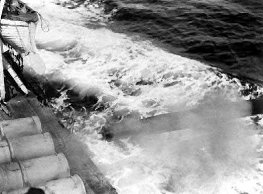 |
| A torpedo launching. It has just left the
tube and cleared the ship. (Photo by Roy Kemp, Toronto Daily Star)
When a torpedo is fired, it travels in a straight line for a certain distance called the "reach". At the end of this period of straight line travel, it may be set to start on a circular course. The arc of the circular path is determined by setting the gyro in the torpedo. At the end of the circular path, the torpedo proceeds to the target in a straight line. This final straight line of the torpedo is called the final track. Haida's torpedo's were normally fired from the Bridge using a rake sight. |
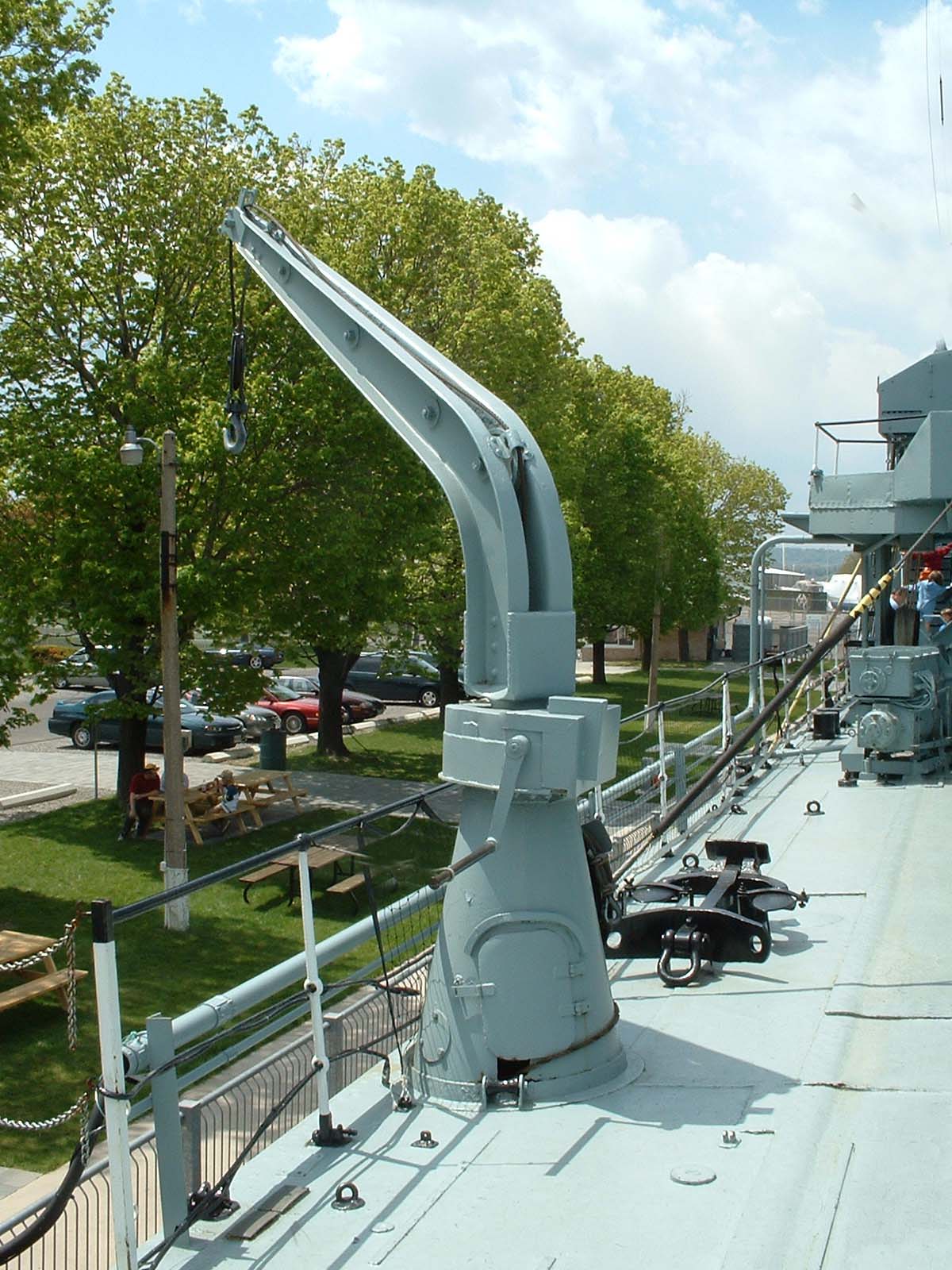 |
| The Torpedo Davit was used to retrieve practice torpedoes. A crank handle mounted on the side of the unit allowed the davit to be rotated in a circular motion .In close proximity and just forward of the davit is the Deck Hoist. By rigging a wire cable from the hoist to the davit, a practice torpedo could be raised from the water to deck level.(Photo by Jerry Proc) |
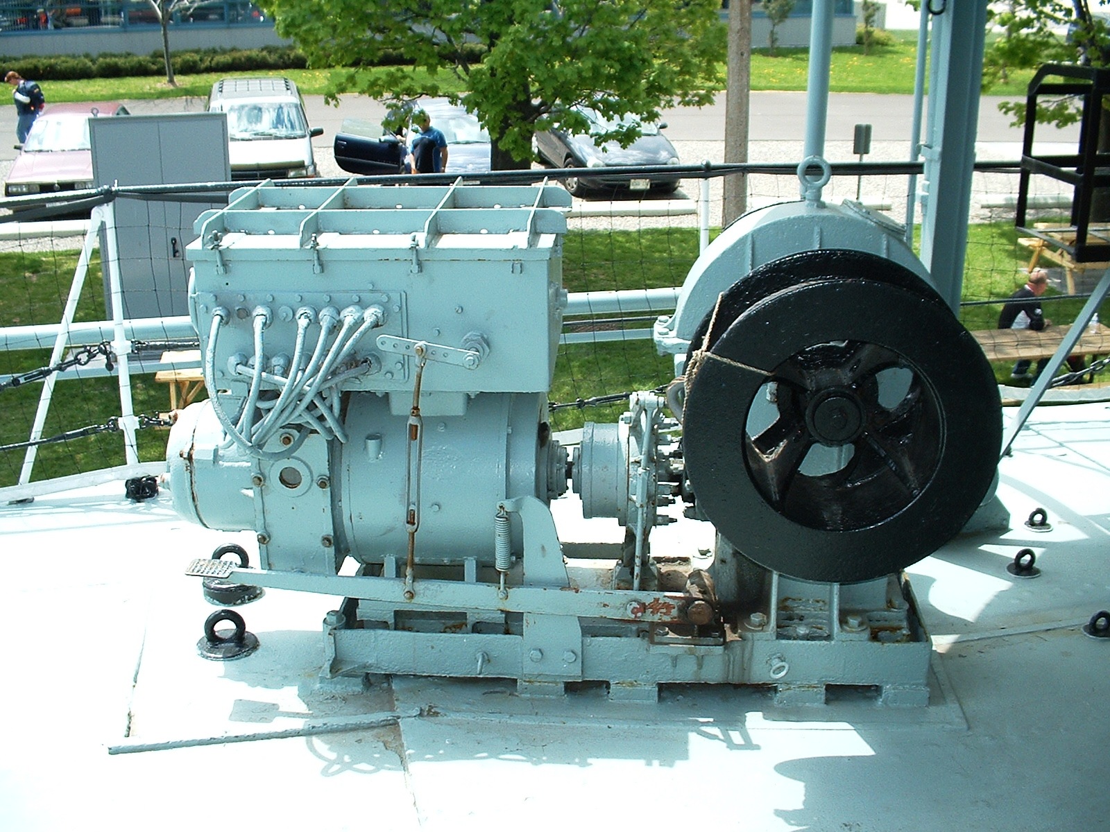 |
| Situated in close proximity to the Torpedo Davit is the Deck Hoist. When a torpedo was to be retrieved, a wire cable would be connected from the drum to the davit. A foot operated clutch engaged the drum to the motor, Motor speed was controlled by a handle connected to a step switch. (Photo by Jerry Proc) |
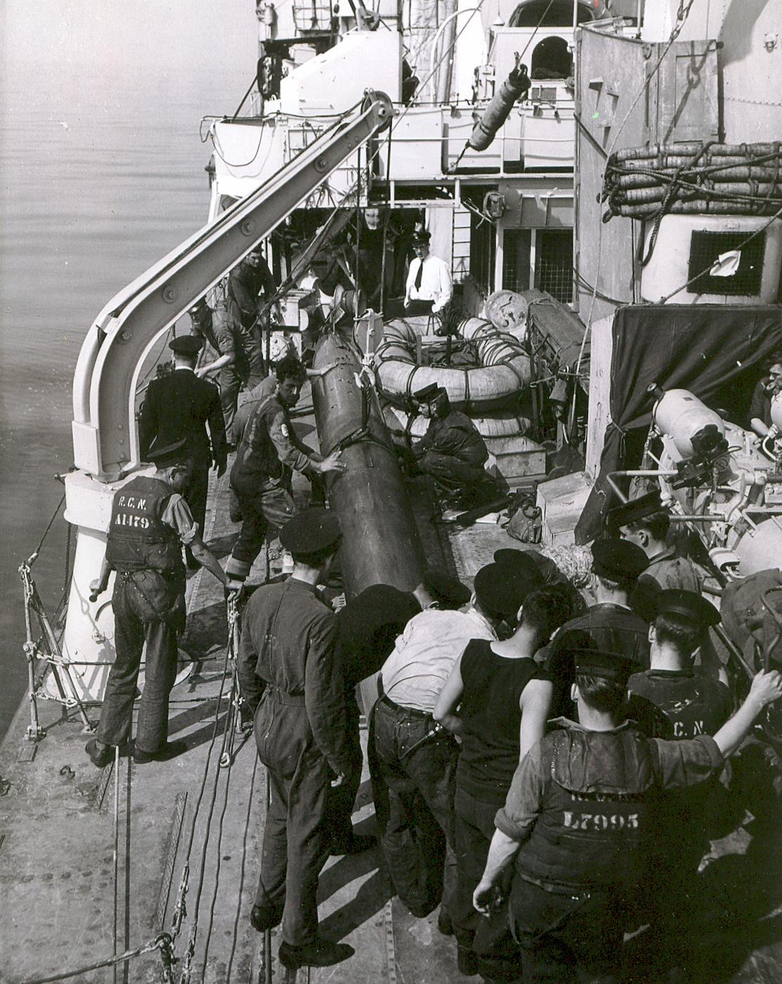 |
| Here , a practice torpedo has just been retrieved. Suspended by the davit, the torpedo will be man-handled back into the tube and be made ready for another practice firing. (HMCS HAIDA Archives.) |
Peter Dixon, HAIDA historian, offers this additional information about the practice torpedo."In peacetime, the torpedoes have "practice warhead" which are filled with water equal to the weight of the Torpex. The cutaway torpedo on HAIDAs jetty has a practice head on it from the Royal Navy Submarine Museum in Gosport, Portsmouth, delivered by HMS BRAVE in 1989(?)
When the torpedo ends its run, the last of the compressed air forces the " poppet valve" on the side to open, thus expelling the water. The torpedo then floats to the surface where it is recovered by the motor seaboat. It is then hoisted aboard by the torpedo davit. Then the torpedo is cleaned, oiled and re-loaded and made ready for perhaps another practice firing. Each torpedo cost $30,000 so It could be a career killer to "lose" a peace time torpedo. The warheads were in the Torpedo Warhead Magazine which is the flat hatch outside the Captains Pantry. Note the eyebolt over it for the chain block to hoist them out of the magazine.
A good example of torpedo activation happened on August 25? 1939 when FRASER and ST.LAURENT were in Vancouver and they received the order from NSHQ to " Ship warheads and proceed to Halifax with all dispatch." And it was that subsequent "all dispatch" passage south to and through the Panama Canal which delayed Canada's Declaration of War until September 10. At 0800 September 10 , FRASER cleared the Eastern entrance and signalled " Canal Transit Completed." Two hours later, Canada Declared War on Germany. (You won't find this in the history books. They say MacKenzie King was demonstrating Canadian independence. "
INTRODUCTION TO TORPEDO FIRE CONTROL Methods of Firing Torpedoes
A destroyer torpedo attack will usually be detected by the target ship in the early stages; therefore the torpedoes must be fired at comparatively long ranges. Unfortunately, this gives the target time to maneuver so as to avoid being hit. For this reason, destroyers usually fire several torpedoes in rapid succession to form a spread or fan-shaped pattern. This procedure greatly increases the possibility of obtaining a hit, and is similar to the method used in antisubmarine warfare in that the fire control problem is solved with respect to the center torpedo in the pattern. A group of destroyers in battle usually fires its torpedoes as a unit, with each ship firing a spread. This combination of spreads produces a pattern which is almost certain to result in some hits. With spread firing it is possible to neglect certain errors which would have to be considered in the fire control problem if a single torpedo were fired to hit a given point of aim.
The two methods of firing torpedoes in a spread are: (1) straight fire, and (2) curved fire. In both methods the spreads are produced by setting small angular offsets into the gyro mechanisms of the individual torpedoes, thus causing each to follow a slightly different course. Curved fire is accomplished by setting an additional uniform offset angle in all the torpedoes in the mount to the angle it is desired for the torpedoes to turn right or left after being launched. Curved fire is used when the desired torpedoes' course is such that straight fire would cause the torpedoes to strike some part of the ship's superstructure.
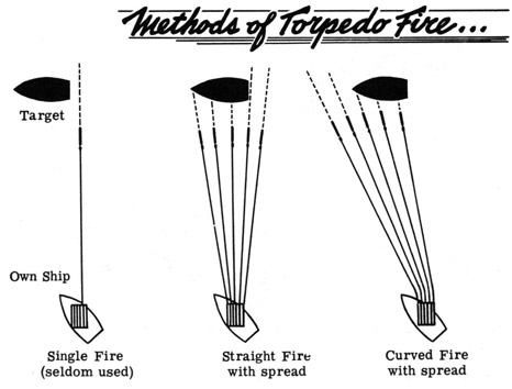 |
| Courtesy USN via HNSA |
| THE FIRE CONTROL PROBLEM |
The torpedo fire control problem is very much like the surface fire control problem. Its solution requires the determination of present target position and prediction of future target position. There are several important differences, however. Instead of traveling in a curved trajectory through the air at very high speed, the fired torpedo travels in a straight line just below the surface of the ocean at relatively low speeds. It is not necessary to correct for wind, drift, level, cross level, earth's curvature, etc. since these factors do not affect the travel of the missile. Due to the nature of the weapon no computations for gun elevation and fuze orders are necessary. Thus the fire control problem for torpedoes is much simpler than for surface or antiaircraft fire.It is necessary to determine only the torpedo course and speed required to have it intercept the target at its future position. The tubes are then trained to start the torpedoes on the required course, and the weapons are fired at the proper time to cause the torpedo to intercept the target.
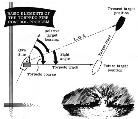 |
| The torpedo track and the target track represent the travel of the torpedo and target respectively from the instant of firing until the time of impact. The above presentation of the problem is much simplified, but serves to illustrate the nature of the basic elements of the fire control problem. (Image courtesy USN via HNSA) |
HAIDA's torpedo mount h missing the Order Instrument. (item 3 in one of the photos). It is believed that it was part of the torpedo fire control solution. This is all that can be said until more information is located.
| DEFENCE AGAINST ACOUSTIC HOMING TORPEDOES |
So far, the explanation about HAIDA's torpedoes are in the context of an offensive weapon. However, HAIDA had to protect herself against the German acoustic torpedo known as GNAT (German Naval Acoustic Torpedo) which was introduced in September 1943. It homed in on the noise created by ships propellors. Nazi Admiral Karl Donitz believed that acoustic torpedoes would restore the killing power of the wolfpack. To counter this weapon, the Allies devised an acoustic decoy to lure the torpedo away from the ship and have it explode a safe distance away. This decoy was known as CAT gear (Counter Acoustic Torpedo). Originally the acronym was known as "Canadian Anti Acoustic Torpedo" . Here it will be referred to as CAT.CAT was towed astern or "streamed" about 150 to 200 yards behind the ship. Its spindle allowed the tow line to twist without flipping the CAT, while the two forty five degree angle arms drove the CAT underwater. A fin kept it on a flat course. The sound of the water running between the two bars was similar to that of the propellers on a ship but much louder ; thus the torpedo would be attracted to the CAT , instead of the ship. Since the GNAT was optimized to home in on acoustic noise around 20 KHz, the CAT gear needed to emulate noise centered on that frequency .
Sometimes the GNAT made repeated passes at the CAT gear until l it ran out of fuel. Two CATs were more effective than one.
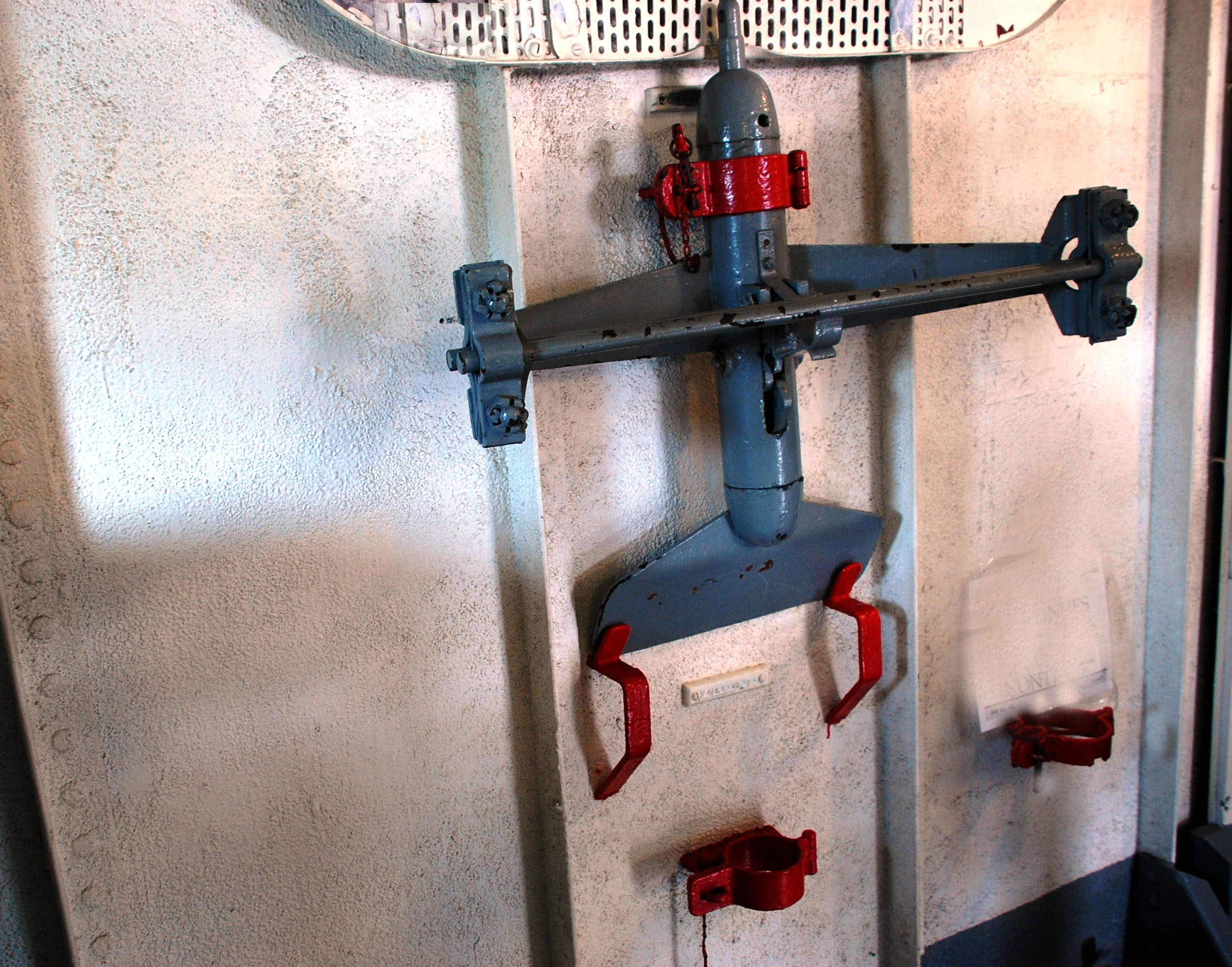 |
| Aboard HAIDA , CAT gear can be found in a stowed position on the forward bulkhead of the Squid Handling Room. Click on image to enlarge. (Photo by Jerry Proc) |
The noise produced by the CAT gear was found to affect the towing ship's ASDIC. A means had to be devised in order to start and stop the CAT noise while streaming. Hal Coverdale of the Naval Research Establishment came up with a solution to the problem. Using an existing CAT example, he devised a means to stop the noise by a sudden release in the tension of the towing cable. The lessons learned, with various refinements, were extended into the post war period.For torpedoes with a contact fuse, the most promising method of avoidance was to have the ship sail on a zig-zag course.
| DEFENCE AGAINST MAGNETIC MINES |
When a ship is built, it will become magnetized by the earth's magnetic field to a certain degree . This residual magnetism can be used to trigger mines that employ a magnetic pistol. The solution to the problem is to degauss the ship.The German magnetic mine which threatened shipping in 1939 was a "ground" mine; that is, it lay on the bottom and was detonated when the residual magnetic field of a ship altered the magnetic field within the mine by some preset amount. Early in WWII , the change of field required was so large that it appeared possible to counter it by reducing the residual field of the ship. Specifically, the vertical component had to be reduced to such a degree that the ship could pass over a mine in, say, 30 feet of water without setting it off.
This was achieved by passing enough current from the ship's generator through a coil of heavy copper wire fitted around the perimeter of the ship to neutralize the effect of the ship at 30 feet below it. Since the gauss was the unit of magnetic field strength in 1940, the process was called degaussing and the field strengths measured were reported in milligauss. The term "degaussing" is credited to a Canadian-born scientist, Sir Charles Coodeve, FRS.
"MOST SECRET" messages sent from the British Admiralty to Dr. G.H. Hemderson and Dr. J.H.L. Johnstone of the Canadian Naval Research Establishment gave the estimated sensitivity of the mine and the probable number of ampereturns for the coil to neutralize a ship of a particular size. 'Within one month, and using this information, the scientists designed a coil system. It was fitted it to a small patrol vessel, HMCS Fleur-de-Lis, and proved its efficiency. It was soon found that most ships needed more than the main coil for protection, and more coils had to be fitted at the forecastle and quarterdeck to take care of permanent and induced longitudinal magnetism.
Aboard HMCS HAIDA, the degaussing system was operated from the #1 Boiler room. All the controls to operate the system were in there. It was fed with 220VDC from the ship's electrical grid. The cable consisted of 21 wires each going around the perimeter of the ship just above the water line. There are three cables in the forward section and two in the after section of the ship. One can follow wire #1 around then connect to wire #2 and so on creating a giant coil. Three coils were fitted in the front due to the additional amount of steel.
The coils, with a controlled current passing through, produce a counter magnetic field. On account of the earth's magnetic field , they had to alter the current for every 10 degrees of latitude. There were tables showing what current and polarity should applied to each circuit. As no two ships are alike, the table would only be relevant for the ship it was on. Another event happened when the degaussing system was turned on. The three magnetic compasses no longer read correctly. If you look at the compass in the Wheelhouse, you will see brass rings under the red and green balls. In the brass ring there are coils. When energized, it makes the compass think the ships residual magnetic field is still present.
In wartime degaussing was turned on if there was any chance of the presence of mines or torpedoes in the ship's operational area. In peacetime, degaussing was not used except for exercises. Ships without degaussing coils could still be degaussed by visiting a degaussing range. Here, the degaussing coils were laid on the sea bed and the ship needed to maneuver directly over the coils. Degaussing ranges were established in Bedford Basin (Halifax), Sydney N.S., Quebec City and Vancouver.
For mines with contact fuses, there was no protection other that avoiding known mine fields or having sharp lookouts on the bridge to spot mines floating on the surface of the sea.
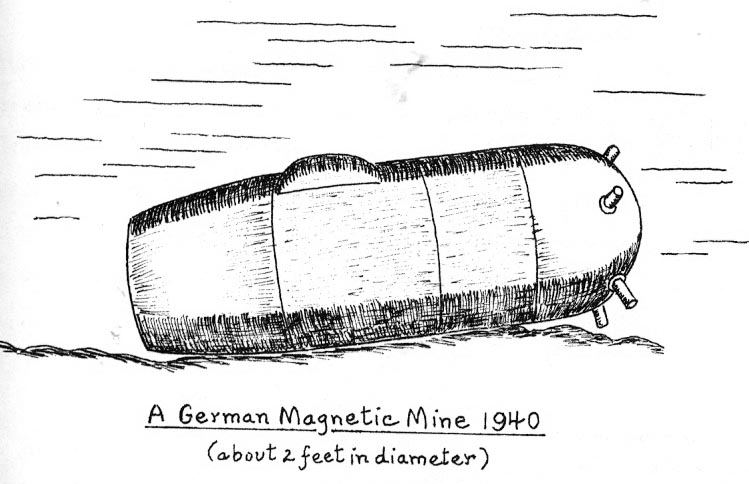 |
| This pictorial of a German magnetic mine was drawn by Latham Jenson. It simply lay on the sea bottom waiting for a ship to pass over it. .(From the book Knots, Volts and Decibels ) |
References:1) "Tin Hats, Oilskins and Seaboots by Latham Jenson.2000 Robin Brass Studio New York NY. 2000
2) Knots , Volts and Decibels by John R. Longard. Published by the Canadian Defence Research Department, Dartmouth NS. 1993.
3) HAIDA FAQ by Neil Bell
Jan 3/25