DECCA NAVIGATOR - RECEIVERS & INDICATORS
(Survey and special-purpose receivers, e.g. Type 990 (RAF Mk 1 Air)
not included in this document).
QM Receiver

|
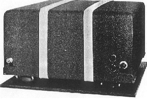
| Here's where it all started. This was one of the original Decca
receivers which saw action on D-Day. Designated Outfit 'QM' , it
was fitted aboard Harbour Defence Motor Launch 1383, which was one
of the vessels actually used on D-Day for survey on the beaches. Someone
has inscribed the vessel's pendant on the front panel. The serial number
of the unit (s/n 112) is actually unit number 12 in the first build series
(Photo
via Walter Blanchard) |
Type: QM
Input Power Requirements: 220 AC at 100 watts
Display: 1 pair of decometers
Number of Channels: 3 (Master, Red, Green)
Dimensions: --
Weight: --
Quantity Produced: 27
Purpose: Prototype receiver for marine navigation
Comments: Developed as a secret wartime navigational aid for the British
Admiralty.
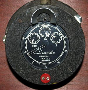 |
| The original decometers were of the gas meter type, and as
such, the first Decca display ever made. Printed on the dial is the name
DR&T, London. which is an abbreviation for Decca Radio & Television.
The gas meter name was used since they were originally made from domestic
gas meters which were designed to count in multiples of ten. (Photo
by David Jones) |
QM1 Receiver
|
|
QM1 photo via Walter Blanchard.
|
Type: QM1
Input Power Requirements: 220 VAC at 90 watts; mains only operation.
Display: One pair of decometers, red/green only.
Dimensions: 21.25 x 16.25 x 12.25 inches
Weight: 80 pounds
Quantity Produced: 40
Purpose: Marine Navigation
Comments: Further development of QM receiver. Used extensively by the
Royal Navy
for mine clearance in the Scheldt Estuary prior to the re-opening of the
Port
of Antwerp in Belgium at the end of WWII.
 |
| The gas meter decometers were fitted with mounting flanges and when
mounted, had a slight downward cant. A red or green marker on the front
denoted the channel. The cable to the receiver plugged into the top of
the unit. This display can be found aboard HMS Belfast in London. (Photo
by David Jones) |
 |
| Modified QM1. The two knobs on the front panel of the QM1 receiver
controlled the zero adjustment for the Decometers - one for each pattern.
They were somewhat sensitive, so later production runs had a small, hinged,
black cover plate installed to cover them up so they couldn't be accidentally
knocked out of adjustment. This gives the initial impression that they
were two different receivers but they were not. Harvey Schwarz is at the
left, Bill O'Brien in the middle and on the right is Edward Lewis, (later
"Sir") Chairman of the Decca Group. (Photo via Walter Blanchard) |
QM2 Receiver
 |
| QM2 Bill O'Brien, |
Type: QM2
Input Power Requirements: 12 VDC at 8 watts; battery operated.
Display: 1 pair of decometers. Similar in operation to QM1.
Number of Channels: 3 (Master, Red, Green)
Dimensions: 18 x 16.5 x 7.5 inches
Weight: 32 pounds
Quantity Produced: 30
Purpose: Portable survey receiver for general use.
Comments: Portable battery powered receiver developed primarily for
use on small ships.
Not equipped for operation on 220 VDC mains. Suitable for general use on
land or
in the air. Used by the Royal Navy in the Scheldt sweeping operations.
 |
| In this historic photo, Bill O'Brien (L) and Harvey Schwarz (R)
study a QM2 receiver. Note the QM1 receiver sitting on the bench adjacent
to the drafting board. (Photo via Walter Blanchard) |
QM3 Receiver
Type: QM3
Input Power Requirements: 220 VAC at 90 watts
Display: 2 pairs of decometers
Number of Channels: 3 (Master, Red, Green)
Dimensions: 21.25 x 16.25 x 12.25 inches
Weight: 80
Quantity Produced: 40
Purpose: Marine navigation
Comments: Modification program to QM1 receiver . Receiver output stages
modified
and two pairs of decometers fitted to permit remote presentation of meter
readings. Slightly smaller than QM1.
 |
| This three meter decometer bowl is awaiting identification but believed
to be from around 1948 since it lacks the Lane Identification feature.
(Photo
by David Jones) |
Mark III Receiver
Type: Mark III
Input Power Requirements: 12/24 at 65 watts for airborne version; 110
VDC at 70
watts for marine version
Display: 1 pair decometers
Number of Channels: 3 (Master, Red, Green Purple)
Dimensions: 18 x 16.5 x 8 inches
Weight: 27.5 pounds
Quantity Produced: Seven 12 volt versions; seven 24 volt versions;
46 marine versions.
Purpose: Either an airborne or marine receiver depending on power source.
Comments: As an airborne set, it was produced for trials only. As a
marine set, they were produced in limited quantity primarily for the Ministry
of Transportation trials.
Mark IV Receiver
Type: Mark IV (MkIVA airborne version shown above)
Input Power Requirements: Airborne - 80 VAC at 1000 cps at 80 watts.
12 VDC at 90 watts.
24 VDC at 90 watts.
Marine - 110 VDC at 90 watts
Display: 1 set of decometers
Number of Channels: 4 (Master, Red, Green and Purple)
Dimensions: 15.5 x 15 x 8 inches
Weight: 31.5
Quantity Produced: --
Purpose: Marine navigation
Comments: Receiver in production as of 1946. Sub-designated QM 's 6,7,8,11,13
depending on chain and frequencies. The very first Mk 4 receiver was fitted
to M.V. ROGATE (Stephenson Clarke Shipping) on Feb 26, 1947
Variant: MkIVA was used for airborne navigation.
 |
This is a two range decometer, used on two range
Lambda Survey Chains for offshore surveys and was manufactured in the 1960's.
The model number indicated is 9039AA Click image to enlarge.
(Photo
courtesy V.K.Lehtoranta, OH2LX) |
Mk V Receiver and Display
 |
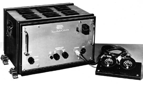
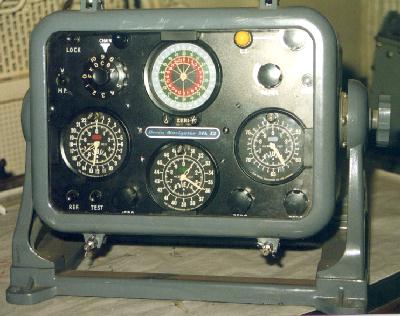
| This is the Decca Mk V (QMS 10). On the left is the decometer
bowl. At the right is the receiver. Reading clockwise from the upper left
corner of the decometer bowl are: Chain Indicator, Lane Identification
Meter, Dimmer control, Purple Decometer, Green Decometer and the Red Decometer.
On the receiver, it is Main Receiver Switch at top center and Channel
Selector Knob at the right side. |
Type: Mk V
Input Power Requirements: Airborne - 24 VDC at 90 watts.
Marine - 110 VDC at 90 watts
Display: 1 set of decometers
Number of Channels: 4 (Master, Red, Green and Purple)
Dimensions: 12 x 15.5 x 8 inches (airborne version)
15.5 x 16.5 x 7.75 inches (marine version)
Weight: 20 pounds (airborne)
62 pounds (marine)
Quantity Produced: --
Purpose: Airborne and marine navigation
Comments: Under development in 1946. The picture above is copied from
the Admiralty Manual of Navigation , 1955. The was Decca's first marine
receiver capable of lane identification. Also applicable to QM's 5,9 and
10.
It should be noted that the Royal Navy used a different designation
for its Decca receivers. All their receivers were purchased, not
rented and although they were the same as the commercial models,
they used the number code QM.
 |
| Here is an example of a Mk V receiver fitted aboard HMS Alliance, a
British submarine commissioned in 1947. (Photo courtesy Royal Navy Submarine
Museum page www.rnsubmus.co.uk) |
 |
| Mark V receiver with chassis cover removed. (Photo courtesy Patrimoine
Radiomaritime web site http://pierre.painset.free.fr) |
MARK XII EQUIPMENT
Decca introduced the Mark XII (valved) marine receiver on 1962 Nov 27,
1962. It supported both Multipulse and Mk. 5 Lane Identification in order
to work with all chains. Used a locked oscillator in the master channel.
The receiving antenna for the Mk 12 style of receiver was normally a
3 part fiberglass tube with a single wire inside. Overall length was about
15 to 18 feet and it came with a wall-plate for fixing to bulkhead or building
wall. Tube diameter was about 1.5 inches and it tapered slightly. The Mk
12 receiver was a wall mounted unit with screw connections via the base.
Decometer and power unit were separate to the receiver. Inside the receiver
unit, the electronics were on 4(?) full length swing down modules. These
receivers were also used as fixed monitors for the chains. These
receivers were also used as fixed monitors for the chains
 |
 |
| An example of a Decca Mk12 receiver. At the left is the
top view; the bottom view is at the right. The chain monitoring receiver
was a modified Mark12 unit. (Photos courtesy of Maritime Museum
of the Atlantic). |
 |
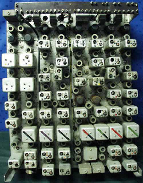
| An internal view of the Mk 12 receiver showing one of the chassis units
swung down for servicing. (Courtesy Decca Navigator News April, 1972) |
 |
| Here is an example of a Decca Mk12 decometer bowl which was donated
to HMCS HAIDA Naval Historic Ship. One major change from the Mk V to the
Mk XII system was the relocation of the chain selector switch from the
receiver to the display unit. (Photo by Jerry Proc) |
The decometer bowl was a cast metal tub with all decometers fitted from
the front face. Only a large, circular multi-pin connector was fitted at
the back for connection to the receiver. The front face was a hinged
cover with a thick glass window. A neoprene seal was set into the cover
and thumbscrews secured it and made it water resistant . The bowl mounted
into a cradle stand and rotated on pivots with a locking wheel at each
end to hold it at the desired angle. It was designed to withstand the rigors
of life on a fishing boat and it could take whatever the wheelhouse crew
threw at it.
 |
 |
| Mk V decometer and receiver. |
Mk XII decometer and receiver. The box
under the orange paper does not belong with the equipment. |
| This side-by-side comparison illustrates the relative dimensions
between the receiver cabinet and the decometer bowl. The equipment in these
two photos are on display at the museum in Port Ness, Isle of Lewis, Hebrides
Islands, Scotland. (Both photos by James Morrison). |
 |
| A typical bulkhead installation in a vessel. This example resides in
the Science Museum London, England. (Photo by Santiago Insua) |
 |
| This detail shows the Decca Navigator antenna feedthrough assembly
aboard HMCS Nootka in 1959. The assembly was made by Decca and was part
of the rental kit. (Photo courtesy of Gary Pollock) |
Mk 13 EQUIPMENT
Not allocated in the series.
Mk. 20 RECEIVER
This was a receiver made by Norwegian STK under name ANARLOF .It used
a digital readout.
Mk. 22 RECEIVER
Prototype for submarine use. Based on Mk. 15 but with decometers and
switchable Lane Identification / Zone Identification meters.
Mk. 23 RECEIVER
A Mk. 19 receiver for land vehicle use. It was built into a Creeth container.
Mk. 24 RECEIVER
A Mk.18 receiver redesigned for small craft. It did not go into production.
MARK 21 EQUIPMENT
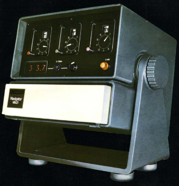 |
| Introduced in November 1969, the Mark 21 was the first receiver where
everything was contained in a single box unit. (Image courtesy of the
Decca Company via Walter Blanchard, RIN) |
DESCRIPTION
The Mark 21 was all solid state marine receiver designed for use with
Decca chains radiating Multipulse (Lane Identification) signals only. It
was intended as a replacement for the Mk 12 receiver. Receiver and display
was housed is a single unit; was suitable for bulkhead, deckhead or table
mounting. Different mains voltages could be accommodated with interchangeable
power unit modules. Power consumption using AC was 25 watts and 35 watts
for DC. It employed locked oscillators on all channels.
When used with a non-Multipulse (V-type) chain, only the decometers
of the Mark 21 receiver would be operative but not the Lane Indicator
(L.I) readout. The L.I. readout may appear to have been triggered
but the numbers displayed were meaningless. The Decometers, however, would
operate normally with the fraction pointers automatically taking up their
correct positions within the Lanes, but the receiver provided no independent
check on the counting action of the Lane and Zone dials. It was recommended
by the British Admiralty that in the absence of L.I. readings, it
was necessary to set the Lane and Zone dials by reference to other navigational
data.
Since the L.I. readings were not valid, possible confusion could be
eliminated by turning the L.I. dimmer anticlockwise to dim the L.I. display.
It was essential to keep the receiver operating continuously in order to
avoid loss of Lane or Zone count, especially if no external data was available.
For all practical purposes, the Mark 21 was a Multipulse only receiver.
When the Mark 21 receiver operated with a Chain designated MP but having
only two slave stations, the fraction pointer of the Decometer associated
with the 'missing' slave station would rotate continuously. Although this
Decometer was not used, it had to be referenced correctly to zero; failure
to do that would adversely affect the L.I. readings for the two patterns
to be used. To do that, the user followed a simple procedure outlined in
the operator's manual.
 |
| Mk 21 installation aboard Her Majesty's Yacht Britannia, now an exhibition
ship at Ocean Terminal, Leith, Edinburgh, Scotland. (Photo by
Santiago Insua) |
MARINE AUTOMATIC PLOTTER
The Decca Marine Automatic Plotter (DMAP for short) provides an accurate
and continuous map presentation of a ships position and at the same time,
producing a complete record of the track made good. It enables ships to
follow any desired course with an accuracy hitherto unobtainable and eliminates
the problems which are encountered when a ship is required to make good
a track which does not coincide with a Decca hyperbolic position line.
Used in conjunction with the Decca Navigator receiver MK V or
with Decca Survey equipment ,this display unit is primarily intended for
operations in which accurate holding of predetermined tracks and the maintenance
of complete track records are essential.
In principle, the DMAP is similar to the Decca Aircraft Flight Log ;
the decometer information is translated into related movements of a roller-mounted
chart and a plotting pen along axes lying at right angles.
The hyperbolic Decca position-line patterns are presented upon the chart
in a rectilinear inverse lattice form; the pen indicates the position
of the ship upon that lattice at any instant, tracing a continuous record
of the track made good as the ship moves across the Decca pattern.
A range of five switch selected scales, from 0.25 inches to 4 inches
per Decca lane, is available for both the pen and the paper, thus giving
chart scales between 1:5,000 and 1:80,000 in the central coverage of a
Decca Chain. These limits fall to some 1:30,000 and 1:500,000 at the extremes
of the coverage area. Further switching gives four possible orientations
of the display each displaced 90 degrees from the next, enabling a rough
approximation to north - or heading-upward display to be obtained
in all parts of the coverage area. The remaining controls, in addition
to their use in setting up the display, provide facilities for producing
latticed charts on a blank chart sheet. This last operation permits
the production of track records in areas for which no prepared charts are
held, By entering the control settings and the decometer readings for any
one point on the track upon the chart , a complete record is obtained
.
The complete DMAP comprises of a display unit and Control Amplifier
(embodying the power supply) . The first houses the actual display head
in which an area of chart approximately 10 in. by 10 in. is visible at
all times along with the operating controls. Its equipped with a
glass, water-resistant cover , a quick release catch permitting easy access
to the chart and controls. The amplifier power supply unit takes
the form of a shelf or bulkhead mounted case. The equipment is designed
for operation from an AC power source and will normally draw its supply
from the converter associated with the Decca receiver.
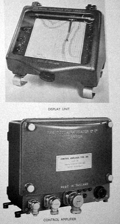 |
| Decca Marine Automatic Plotter (Decca Navigator Company photo) |
DECCA AERONAUTICAL RECEIVERS, OTHER TYPES AND ENHANCEMENTS
Mark 6, 7, 8, 9, and 10 were all airborne-only receivers.
Mk 6 RECEIVER
 |
|
1949: Decca Mk 6 Aircraft Receiver. (Decca Navigator
Company photo)
|
 |
| This diagram shows the external controls of the MK 6 receiver. (Decca
Navigator Company image) |
SPECS
Receiver Dimensions: 21" W x 8.5" H x 11" D.
Receiver weight: 24.5 lbs.
Capability: Can receive up to 5 chains. Remotely controlled from cockpit.
Power Unit Dimensions: 6"W x 8.5"H x 11"D
Power Unit weight: 19 lbs.
Power Input 24 VDC@ 12.5 amps
Comment: Airborne receiver electrically similar to Mk. 5
 |
| Pilot's remote control for the Mark 6 receiver. (Decca Navigator
Company image) |
 |
| 1949: Mark 6 decometer panel. (Courtesy "The Aeroplane",
June 1949) |
FLIGHT PLOTTER
To simplify the problem of navigating in all types of aircraft, Decca
came up with a solution in the form of a presentation suitable for pilot
navigation.
Simple route graphs prepared by the Decca Navigator Company for all
European air routes were inserted in the Flight Plotter and the pilot only
needed to turn the knobs of the Flight Plotter to bring the perspex cursor
to correspond to the Decometer readings at any point on his flight, to
obtain, without further effort, not only a position fix, but also range
and bearing from destination. The pilot was entirely free to make any deviation
from route when circumstances necessitated and was able to use this simple
and efficient method of navigation throughout his flight.
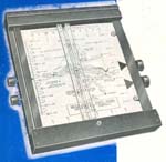 |
1949: Decca Flight Plotter. Click to enlarge.
It bears no model or part identification because it was the very first
one that Decca produced. The complete Flight Plotter illustrated here contains
the Route Graph for the Metropolitan Control Zone, which enabled the pilot
to continuously and accurately plot his approaches along the corridors
to the principal Metropolitan airfields in Europe. Weight of the
Flight Plotter is 4.5 pounds and its dimensions are 12"W x 14" H x 2"D.
(Decca Navigator Company photo) |
This device, in conjunction with the Decca Navigator Mark VI
receiver and the existing Decca chains of the day provided a realistic
and practical aid to navigation in Europe.
| SAMPLE ROUTE GRAPHS FOR THE FLIGHT
PLOTTER |
 |
Click to enlarge. This is the Route Graph for
the area north of London enabled range and bearing from Luton Control Point
to be obtained at any time during the flight. This. Route Graph was used
for general flying in this area and for all routes running into the London
Control Zone from the North East area. (Graphic courtesy Decca Navigator
Company) |
 |
Click to enlarge. The Route Graph shown here
is for a typical European air route such as Brussels to London. (Graphic
courtesy Decca Navigator Company) |
FLIGHT LOG
The Decca Flight Log was a logical extension of the Flight Plotter and
was made possible by the use of the new map projection technique used in
the Flight Potter. The map of the route to be flown was carried on a cylinder,
measuring 16 inches in length and 7.5 inches in diameter. As the cylinder
was rotated about its axis by the drive unit, it was traversed by a Perspex
scale. A marker carried by this scale made, on the map, a continuous recording
of the track of the aircraft over the ground.
As was the case with the Plotter, the map could be varied to suit particular
requirements. Complete flights of up to 300 miles could be covered on one
map, with separate diagrams to cover the approach pattern, traffic holding
procedure, etc.
Decca co-ordinates would not normally be marked in on the map but would
be printed in the appropriate colours on the reverse side. If it was desired
to check the Log for accuracy, the inside of the drum could be illuminated,
to make the co-ordinates visible. Readings could then be taken from the
receiver and plotted in the usual way on the map. A time plotter was also
provided for optional use. When switched on, it caused the pencil
marker to deviate at given intervals and thus provided a record not only
of the track flown by the aircraft, but of the time taken over various
sections throughout the flight.
Apart from the obvious value of the Log for navigational use, it had
an important application as a flight recorder. The installation of a Log
in the rear of an aircraft used for navigational training, for instance,
would enable a complete picture of the pupil's flight to be obtained and
a post morteum could be held if necessary. Similarly, aircraft operators
would find the installation of a Log useful as a means of checking the
movements of their aircraft.
In 1949, the Flight Log only existed in prototype form and flight trials
had not yet commenced. It had, however, been extensively tested in road
trials, and some impressive results were obtained. In one test, a vehicle
equipped with the Flight Log had a run down the Kingston By-pass
(in the UK). The engineers watched the Log draw a line accurately down
the centre of the road marked on the map. They did however, notice that
telegraph and trolley bus wires sometimes caused serious deviations. At
short ranges, this would make road use of the instrument impracticable.
It was anticipated that Flight Log would be available by 1950.
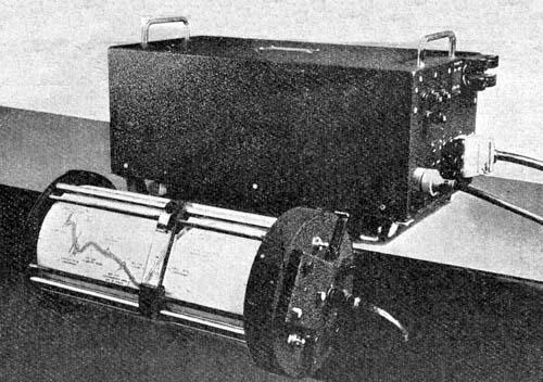 |
| Essential components of the Flight Log were a torque amplifier, a drive
unit, a display unit, and the Mark 6 Decca Navigator Receiver which fed
the drive unit. In 1949, only prototypes of the Flight Log were available.
(Decca Navigator Company photo) |
Mk 7 RECEIVER
Airborne receiver using locked oscillator; phase comparison directly
at slave frequencies.
Mk 8 RECEIVER
Airborne receiver same as Mk. 6 but fitted in standard SBAC racking.
This receiver was used by the RAF. In 1955, eight Valiants and
ten Shackletons were fitted with Mk 8 receivers and flight logs for Operation
Grapple, the nuclear bomb tests at Christmas Island. It was also by (former)
British European Airways on their Argosy freighter aircraft. The Ledex
switch assemblies used in the Mk8s were often the root cause of many problems
although the tubes seemed to have a very long life span and were not changed
that often.
Variant: Mk. 8A - Airborne receiver based on Mk. 8 but fitted
in smaller half-ATR ARINC racking.
 |
| Mk 8 receiver components. Source DECTRA marketing brochure. (Photo
courtesy Decca Navigator Company) |
 |
 |
| Closeup of the RED Mk VIII aeronautical decometer. Type 274-Z. P/N
10Q316774. (E-bay photo) |
Rear view of GREEN Mk VIII aeronautical decometer.
Type 274Z. P/N10Q16773 . (Photo courtesy Denis Chouinard) |
Mk 9 RECEIVER
Airborne receiver without Land Identification feature.
 |
| Mk 9 receiver components. Source DECTRA marketing brochure. (Photo
courtesy Decca Navigator Company) |
Mk 10 RECEIVER
Major new design of the airborne receiver for use in the DECTRA system
. It employed locked oscillators on all channels; automatic Lane Identification
using the Multipulse method; had the zone identification feature; phase
comparison at 1F (14 kHz).
 |
Mk 10 receiver components. Click to enlarge.
Source DECTRA marketing brochure. Mk 10 receiver dimensions/weight: 24
in W x 15.5 in D x 9.25" H / 50 lbs. (Photo courtesy Decca Navigator
Company) |
 |
| Mk 10 receiver with cover off and two modules extended for service.
(Decca
photo) |
Mk 11 RECEIVER
First solid-state receiver. Used with the Omnitrac/Harco system.
Employed electromechanical tracking filters and digital outputs.
Mk 14 RECEIVER
This was an airborne receiver prototype using locked oscillators s on
all channels and outputs at 1F for external phase comparison. No Lane Identification
or Zone Identification.
Mk 15 RECEIVER
This was a development of the Mk. 14 receiver for use in DANAC incorporating
full Land Identification and Zone Identification. Used with
computer types 1910 or 9810.
The Mk15s were used on British European Airways Trident aircraft, and
were also a standard fit in many UK registered Jet Ranger helicopters.
On the Mk15s, various transistors often failed along with crystals. One
of the most common "squawks was that the radio would not sync up, primarily
either on Red, Green or Purple. This was due to either crystal aging
or mechanical damage (drop shock) and hence no sync.
Mk 16 RECEIVER
It was the same as Mk.15 but with phase comparison circuits built-in;
it had fractional zone outputs for the OMNITRAC system.
Mk 16 saw service during the early days of testing the supersonic Concorde
aircraft and more specifically, during the period of Concordes Inertial
Navigation System certification. It was built in a ¾ long ATR case
and was essentially a Mk 15 with the navigation computer bolted on the
back. Specially selected components were incorporated in this radio and
it did track even when the aircraft was flying supersonic.
Mk 17 RECEIVER
This was a Mk. 16 receiver modified for use with the DECTRA System.
Mk 18 RECEIVER
This was an experimental, batttery operated "mini DECCA" system for
the British Army.
Mk 19 RECEIVER
A multi-purpose unit for military use which incorporated both Mk. 8
and Mk. 15 facilities. It could be retro-fitted into Mk. 8 racking. Mk
19 was used by RAF.
There was also a special military receiver known in Decca as the "Type
990" and known by the RAF as "Mk 1 (Air)" . It had special anti-jam and
other features. Quite a lot of them were built and fitted into Canberra
aircraft in the late 1960's.
Receivers such as the QM5, QM9 and QM10 could only receive the standard
'V' type transmissions. Mark 12 receivers were designed to receive both
Mark V and the newer Multipulse (MP) transmissions.
Due to the need to have stable, accurate monitoring site performance,
a lot of research went into antenna design. An active antenna was designed
for station monitoring that had a graphite coated radome designed to reduce
interference from charged water particles. The Mk 21 used a short,
stubby, cylindrical antenna, approximately 24 inches overall and
3.5 inches diameter. This included a head amp and was connected via a single
cord to the receiver.
Monitoring vehicles were fitted with Mk 12 and Mk 21 receivers for purposes
of monitoring chains. These used a mixture of antennas including a lab-made
custom design comprising of a 2 foot of 6 inch pipe with a metal
sphere cap (not recommended for low headroom parking).
There was a later version (Mk30 perhaps) receiver that used a ring of
LED segments to form the decometers but it not clear if these ever went
into production. The analog Decometer-type display always seemed to be
more reassuring than static lights.
 |
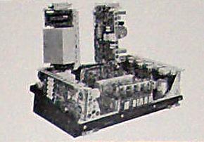
This was the airborne version of the Decca receiver called Dectrac
Mk 19/15A3 s/n 175 built in 1980. (Courtesy of web page: http://perso.libertysurf.fr/webmeynier/aero/
80084.htm) |
 |
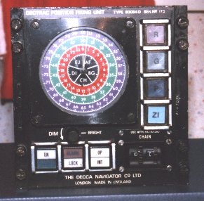
| This is the receiver control unit ( Type 8954) for the Mk 19
airborne Decca receiver (Photo courtesy Decca Navigator Company) |
 |
 |
 |
 |
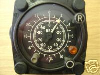
| The Model 961 flight indicator was part of the Mark
19 system and was used by the RAF mainly in helicopters and the Hawker
Siddeley Andover Transport aircraft. The unit depicted (s/n 209) was manufactured
in May 1974. Click on photo to enlarge. (Photos by Santiago Insua) |
MODERN EQUIPMENT
By the end of the Decca system, the receivers were designed with
built in processors. The display would read latitude and longitude directly
thus dropping the need to procure and use lattice charts.
 |
| Two examples of direct reading Decca receivers are the Model SAH-1D
(left) and the Navigator DR-702. The model SAH was sold to the Japanese
market hence the reason for the Japanese characters on the keypad. (Photo
courtesy of the Sena Co, Ltd, Tokyo, Japan). |
DANAC
DANAC stands for Decca Area Navigation Airborne
Computer.
In this system, the position-fix information delivered by a Decca Navigator
receiver is continuously presented, via the computer, on a Flight Log pictorial
display. This product was introduced in 1969.
The system is largely automatic, but permits the user to monitor all
stages of operation. A basic principle is that the computer, during initial
setup and under certain other conditions, requests the user to confirm
that he accepts the displayed position of the aircraft. If the position
is not acceptable he can adjust the display using the prescribed procedures.
A) In addition to the Danac units, the Mark 15 system has an antenna
amplifier Type 1995
 |
| A complete DANAC system. (Graphic courtesy of Thales http://www.ravl.co.uk/press/pr38.html) |
B) The additional units of the Mark 19 system are:-
Antenna amplifier Type 1995
Mark 19 receiver Type 1904
Receiver controller Type 8954
Decometers (red, green, purple) Type 274
Lane identification meter Type 275
Zone identification meter Type 1956
Although Danac can work in a restricted mode with Decca chains of the
early type (known as V or sometimes Mark V chains), of which a few remain
in service, it is intended for use with MP chains. This term stands for
the multipulse (also known as Mark 10) signals which the chain radiates
every 20 seconds. The MP signals perform an automatic function in the receiver
known as "notching" or automatic lane setting, with the object of resolving
ambiguities that could otherwise permit the displayed position to be in
error by some fraction of a zone, and also provide zone identification.
More on MP in the Decca Transmitter section.
Additional references or credits:
1) Walter Blanchard <wblanch(at)ntlworld.com]
2) Danac Operating Instructions Manual, June 1979. Decca
Navigator, New Malden, Surrey
3) Extracts from Decca's Genealogy provided courtesy
Walter Blanchard, Royal Navigation Institute.
4) Stuart A Wolf <stuart.wolf(at)nats.co.uk>
5) James Morrison Decca photos. http://www.flickr.com/photos/jamesm/107572653/in/set-72057594120797676/
6) DECTRA marketing brochure published by the Decca Navigator
Company.
7) Denis Chouinard <denischouinard(at)enter-net.com>
8) Santiago Insua <hwasp(at)hotmail.com>
9) Matthew Parker <parkermat(at)hotmail.com>
10) David Jones <dsjjones(at)bellsouth.net>
Back to Decca Intro Page
May 30/08