|
| Interior view of the AN/APN-4 Loran A receiver. .(Photo courtesy ATS Technica Wwb page) |
INTRODUCTIONNo great effort was put into hyperbolic navaids in the US until it became clear that America could not avoid involvement in W.W. II. Before 1940, the US military forces were small and under funded, and there was no separate Air Force, only Army and Navy Air Corps. Like most other military air arms of the time, little attention had been paid to the problems of accurate navigation over hostile territory and no requirement for accurate radio navaids had been formally stated. In 1940, under the aegis of the National Defense Research Committee, a Microwave Committee was set up to examine what new developments would be needed if the US became involved in the European War. One of these (known as Project 3 according to the official history of the period, but as Project C according to Professor Jack Pierce, who was a member of the development team) was to be a pulsed hyperbolic radio navigation system operating in the low end of the VHF spectrum, at about 30 MHz - very like Gee, which the Americans knew nothing about at the time. It eventually became the Loran-A system, out of which Loran-C was born. Loran-A operated in the 1850 to 1950 kHz band, used pulse-time difference as its operating principle and generally speaking had a day/night range of about 800 to 1600 nm depending on whose reference you read.
HISTORYThe US Army Signal Corps Technical Committee, at a meeting on October 1, 1940, wrote a specification calling for a precision radio navigation system with an accuracy of at least 1000 feet at a range of 200 miles. This was adopted as 'Project 3 (or C)' by the Microwave Committee and initial orders for equipment were placed in December 1940. In early summer 1941 it was handed over to the Radiation Laboratory Navigation Group, who, after some study, decided that the attainable ranges using 30 MHz might be too low for American requirements and that better results could be obtained at lower frequencies in the HF band. While the original 30 MHz transmitters were still being built, new transmitters were obtained to use frequencies between 3 and 8 MHz and experimental transmissions started in summer 1941. It became clear almost immediately that the lower frequencies around 3 MHz were more stable, but there were considerable difficulties making accurate time delay measurements. This was the same problem the Gee development team was having in the UK, but was compounded by the much longer pulses Loran-A was using at its lower frequencies. It should be remembered that at this time virtually no work had been done on high power low frequency pulse transmission, and the technique was in its infancy.
While these tests were proceeding, information was received from the UK liaison office in the USA about the Gee system, including some details of how Gee time measurements were being made. The US team were trying to use a circular time base to increase accuracy but had found it difficult, so the British technique of using delayed and strobed time bases was of great interest and was adopted immediately. Also, now having realized how far work had advanced on Gee, the US team saw no reason to duplicate the British work and abandoned any further work on the original Project 3. They foresaw that the main application of the new system would be for naval convoy work, and long range over sea water would be important. Comparative trials at different frequencies evaluating groundwave and skywave performance eventually led to the choice of 1.950 MHz as optimum and all subsequent development work used this frequency. There was at one time an intention to supplement it with a second frequency of around 7.5 MHz for daytime long-range use, but it. was never implemented except for test purposes. For anyone who has used the APN Loran receiver, this explains the mystery of why there was a fourth position on the frequency selector marked 'HF'.
|
| Interior view of the AN/APN-4 Loran A receiver. .(Photo courtesy ATS Technica Wwb page) |
In mid-1942, R. J. Dippy, who had invented the Gee system, was sent to the USA for eight months to assist in Loran development. Many of the techniques used in Gee were adopted, and it was he who insisted that the Loran and Gee receivers were made physically interchangeable so that any RAF or USAAF aircraft fitted for one could use the other by simply swapping units. This was still to prove valuable, long after the war had finished, for Transport Command navigators flying the Australia run from the UK who could plug in the appropriate set depending on where they were. He also designed the ground station timing and synchronization equipment and his assistance speeded up Loran development considerably. Once design had been finalized, production went ahead rapidly. The first Loran-A pair was on the air permanently by June 1942 (Montauk Point, NY, and Fenwick Is, Del.), and by October there were additional stations along the Canadian east coast. The system became operational in early 1943, and late that year stations were established in Greenland, Iceland, the Faeroes and the Hebrides to complete the North Atlantic cover, some being operated by the Royal Navy. At the request of the RAF, another station was put into the Shetlands to cover Norway, and Loran was eventually used by over 450 aircraft of Coastal Command.
But it was in the Pacific that Loran made its greatest direct contribution to winning the war. Distances in the Pacific Ocean are enormous. As American forces moved westward, air fields were built on many of the small islands and atolls that dot the ocean beyond Hawaii. The limited range of many World War II aircraft demanded that they frequently land and refuel. Navigation by celestial observations is possible only when weather permits and, moreover, it requires a highly trained man who does little on the plane except navigate. Because of the lengthy training required, celestial navigators, particularly on Army Air Corps planes, were extremely scarce. Thus it was that loran provided the easy-to-use, accurate navigational system required to and the air fields so necessary for refueling.The intensive bombing of Japan began as soon as air bases could be secured near enough for aircraft to make the round trip. Accurate navigation was necessary not only for precision bombing, but also for carrying a maximum bomb load instead of a large reserve of gasoline. The loran system provided the means for this accurate navigation. By the end of World War II there were 75 standard loran stations serving the needs of aircraft and vessels in operation with over 75,000 receivers in use. Coverage in the Japanese and East China Sea Areas was extended in the 1950's
The crews of Loran stations varied somewhat in size, depending on their locations. They have averaged about fifteen men. As the stations had to be entirely self-sufficient, they had cooks, hospital corpsmen, damage controlmen, and enginemen, in addition to the electronic technicians who operated and maintained the transmitters. Each station was commanded by a commissioned officer, usually a lieutenant (junior grade ), with a chief petty officer as second in command. Prospective commanding officers were given a short training course in Loran and administration before assignment. Command of a Loran station was almost invariably a young a Coast Guard officer's first independent assignment, and it provided an excellent opportunity for him to demonstrate his leadership qualities. Many young others dreaded Loran duty because of the isolation, but after it is over, nearly all of them felt it had been well worthwhile. At isolated stations, tours of duty were for one year. The great majority of Loran stations were supplied with fuel, bulky spare parts, and large staple items by a Coast Guard supply ship which called once or twice a year. Unless they were located near a large community, Loran stations received mail, personnel, fresh stores, and emergency spare parts by Coast Guard airplane. Most stations had their own airstrip.
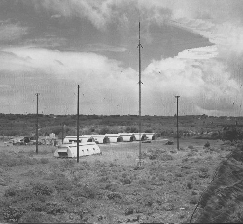
This was a typical USCG Loran-A station in the SW Pacific. Generally speaking, Loran-A had an average expected accuracy of 1 percent of the distance between the navigator and the stations according to the U.S. Coast Guard in 1949. (Photo courtesy Ken Laesser's Coast Guard History Page) Retired Maj. Terry Kennedy, served as an navigator in the USAF for 20 years along with service for NSA. Here, he relates some of the difficulties of navigating in Canadas north before the widespread deployment of navigation aids.
In 1958-59, I was flying C-47 (Dakota) Dewline resupply in north east Canada (via Thule Greenland, Alert, Eureka, Resolute, Fletcher, and Goose Bay, Newfoundland,. Ive had many experiences navigating by the seat of my pants as they used to say. There was no radar; the magnetic north was located below me; the weather was both overcast and undercast. It was just dead reckoning to find various ice islands, all drifting about in the Beaufort Sea.
Resupply for ice island T-3 was hampered by a mix of varying obstacles. Due to the iceberg's constantly moving location, resupply had to be operated from two air bases - Point Barrow, Alaska and Thule Air Base, Greenland. At that time, flights were conducted without navigational aids, and the aircraft landing on the constantly moving iceberg T-3 was performed solely by dead reckoning and celestial navigation, which was often hampered by long periods of twilight which prevented celestial observation. In addition, because the nearest alternate air bases were 475 miles (764 km) away, potential in-flight emergencies could result in fatal outcomes. In this regard, pilots and their crews had to calculate cargo and fuel loads precisely to insure not only a safe landing but also a safe return from the iceberg."
In many places throughout the Pacific, Coast guardsmen were the only Americans ever seen by the natives, and it is to their credit that unpleasant incidents were few and far between. In fact, relationships were usually excellent. A good example was the Okinawa Loran Station which was located on a small island just of Okinawa itself . Here on Ichi Benare, the Loran station personnel were the only Americans. The island is infested with a venomous snake, a species of pit viper. When left untreated, the bite of this snake is usually fatal. The hospital corpsman of the station always keeps a supply of anti-venom for station use, but he also used it to treat those natives unfortunate enough to be snakebite. On the wall of this station hung a scroll, signed by the mayor of the native village, expressing thanks fox having saved so many of the villagers' lives.
The Pusan Loran Station was part of the East China Sea chain, while the other two stations were located on the west coast of Japan. This chain was established to furnish accurate positions to United States aircraft approaching the Korean Peninsula. The Pusan station was built on a bluff overlooking the East China Sea, a few miles from the city of Pusan, Korea. Ever since it was first built, this station was harassed by bandits. It was completely surrounded by barbed wire, has many foxholes and slit trenches, and for years personnel were frequently called upon to defend themselves against marauders.
Still another station was Naulo Point located on the west coast of Luzon in the Philippines. Because of its dry and relatively cool weather (unlike that of other Philippine stations ) Loran people called it "The Garden Spot of the Pacific.'' It is in the heart of what was once the "Huk country" and during the Huk uprisings was guarded continuously by a company of United States Marines. For years the barbed wire entanglements, entrenchments, and floodlights remained as a mute reminder of former violence.
In 1965 Loran stations were established in Portugal and the Azores. One major difference in the way Loran-A operated compared with Gee was that its transmitters operated in pairs rather than as chains.
LORAN SECURITY
Because the LORAN program was a secret during WWII, a security concept was applied whereby each station was designated with a letter so not to reveal the transmitter location in case any of the Loran charts/tables should fall into enemy hands.Loran stations also had Unit designators. The Unit number (i.e. Unit 10 for Nantucket) was used for issuing orders to personnel assigned to a station and all correspondence with the goal in mind of not revealing the transmitter location. It was decided early on in the program that the station and personnel were expendable and could not be protected.
There were other designators used post war. Dope 1/2/3 were code names for the stations in Greenland during the Cold War. This holds true for the stations that were established to support the Korean War (ELMO 1 - 7).
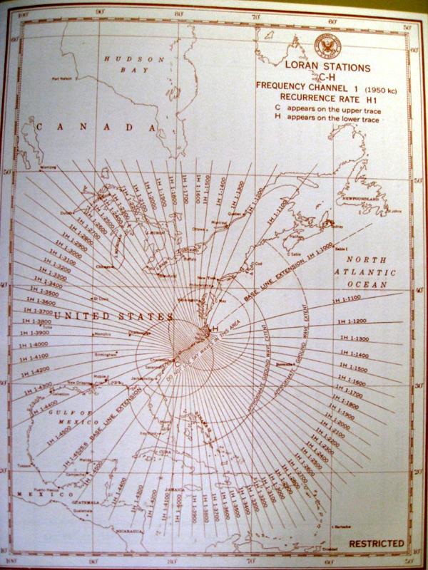 |
This Loran-A chart shows the WWII era letter designations used by two US East coast stations. Station 'C' is Folly Beach and 'H' is Bodie Island. Click to enlarge. (Chart provided by Bill Dietz, Loran A History web site ) |
EARLY EQUIPMENTBecause of vacuum tube size and power requirements, LORAN only saw shipboard use initially because the equipment was too large for aircraft. By 1943 an airborne LORAN, the APN-4, was small enough to be used on large bombers and patrol aircraft. The APN-4 consisted of two units each about 1 ft. x 2 ft by 2.5 ft. One unit consisted of the power supply while the other contained the oscilloscope display tube, timing circuits and receiver. Together they weighed about 80 pounds. By 1945 the APN-9 came into use at an amazing weight reduction. It only weighed 40 pounds.
AN/APN-9 Loran 'A' set. Commercial fishermen also used these after WW2 until something better came on the market. (Image source unknown.) The oscilloscope screen was about four inches in diameter and would display a station master and associated slave signal from about 1500 miles over water and 600 miles over land. With practice a fix could be determined in about three minutes. As an example, the minimum error for navigating the 1400 miles to Japan from Tinian was about 28 miles. With two successive fixes ground speed, drift, and ETA could be determined. The relative simplicity of LORAN and the fact that it could be used regardless of weather made it invaluable an invaluable navigational tool until the aircraft arrived over Japan when airborne radar provided a more accurate fix. For some unknown reason the Japanese either never tried or failed to jam any of the LORAN systems.
For a comprehensive look on the placement of Loran chains during WWII, please select this link.PRINCIPLES OF OPERATION
Loran provided facilities whereby ships and aircraft derived their position at long distances. The system required at least three transmitting stations for each 'chain', and the observer used a special Loran receiver. A chain consisted of one master and two slave stations. Differences in the arrival time of pulses from a pair of stations was measured and displayed on the face of a cathode ray tube. Each fix required two observations and the operation normally took about five minutes. The readings were then transposed to a Loran lattice chart and position could be plotted. In some cases readings were referenced to special Loran tables. Because Loran-A signals were pulsed and not continuous transmissions, tremendous peak power levels could be achieved by a relatively small transmitter. The maximum reliable range for Loran-A was 700 miles by day and 1,400 miles at night.
SIGNAL CHARACTERISTICS
Each transmission pulse lasted about 40 microseconds and reoccurred at regular, accurately controlled intervals. This interval, called the Pulse Repetition Interval (P.R.I.) varied for each station and lasted between 29,000 and 40,000 µs. These pulses provided precise index marks for use in time measurements. The transmissions of corresponding master and slave pulses were separated by a fixed time interval which consisted of the time for a signal to travel from the master to the slave, plus one-half the P.R.I., plus an additional small time called the 'coding delay'. It should be noted that the observer is interested only in measuring the difference between the time of arrival of the two pulses, and not the actual time taken for each pulse to reach the receiver. There was no need, therefore, for an absolute synchronization of the receiver time base with the transmitter.
At all points in the coverage area, the time interval between a master pulse and the next slave pulse was greater than the interval between a slave pulse and the next master pulse. That methodology provided a positive method of identifying the signals arriving from each station, even though their actual appearance was similar. In the measuring process, the time difference was always measured from the master pulse to the slave pulse, and the time delay of one half of the pulse recurrence interval was automatically removed. The lines of constant time difference for each pair of stations were pre-computed, taking into consideration the curvature and eccentricity of the Earth, the time for the master pulse to reach the slave station, and the coding delay. These "hyperbolic" lines were made available in the form of overprinted charts and tables. (Graphic courtesy Admiralty Manual of Navigation).
A sample Loran chart showing the location of a master and two slave stations. Also shown are station identifiers and time differences on the curves. (Graphic courtesy of Electronic Communications). ARRANGEMENT OF STATION PAIRS
When a common master controlled two slaves, the master was called a 'double pulsed' station because it transmitted two entirely separate sets of pulses, one set paired with the pulses from each adjacent station. Pairs of Loran stations were situated up to 600 miles apart.
A dual rate LORAN-A station did not require two separate transmitter or extra space. Dual rate used one transmitter that was time shared between two pulse group schedules with special blanking rules to prevent overlap. Dual rate LORAN A stations did not require extra staff. The workload didnt increase enough to justify more operators, because the dual rate function was handled almost entirely by timing equipment, not by people.
The L and H letters in LORAN-A rates identify two different pulsetiming group families:
L = Low?rate (longer timing group period)
H = High?rate (shorter timing group period)Loran transmitters emitted 40 microsecond pulses. For H-rate pairs, the basic recurrence interval was every 30,000 microseconds; for L-rate pairs, 40,000 microseconds; and for S-rate pairs, 50,000 microseconds Each pulse had a peak power in excess of 200,000 watts, but since the duty cycle (the ratio of time the transmitter is on duty) for an L-rate pair, for example, is only 40/40,000, or 0.001, of the time, the transmitter has an average power output of only 200 watts or so. (200,000 x 0.001).
If any trouble occurred at either the master or the slave station that might impair the accuracy of the pulse timing, the transmitters operated on a 2 sec ON then 2 second OFF mode. This appeared to the operator as a blinking signal. Blinking signals were not used for navigation.
RECEPTION OF SIGNALS
In order to properly display the pulses to be measured, the receiver's time base had to synchronized so the length of the trace on the C.R.T. matched the P.R.I. of the station. Failing to do so would cause the pulses to appear as if they were drifting to the left or to the right depending if the time base was too short or too long respectively.
The face of the C.R.T. in the receiver displayed two time base lines because a pair of stations were always being compared. For convenience, the upper trace was called the "A" trace and the lower one the "B" trace. By convention, the master station was displayed on the upper trace and the slave on the lower one. The time difference measurement was the horizontal distance from the master pulse to the slave pulse.
In an attempt to gain longer-range navigation, a variant of Loran-A was developed. It was known as SS (sky-wave-synchronized) Loran In the SS Loran system, the slave station of a pair was synchronized by a sky-wave pulse reflected from the 'E' layer, rather than by the ground wave as in standard Loran. This allowed the master and slave stations to be separated by as much as 1000 to 1200 miles. The Loran charts were calibrated in terms of sky waves, instead of ground waves, so that correction factors were unnecessary when sky waves were used. A disadvantage of the system was encountered when the indicator was located close to either or both stations, since erratic reception resulted when the angle of reflection of the sky wave from the.E layer approached the critical angle. As the critical angle was approached, the radio waves exhibited increasing penetrating power and would go entirely or part way through the 'E' layer.
This is a view of the now dismantled Coast Guard Loran 'A' Station at Cape Sarichef, Alaska taken around 1975-76. The site was located on Unimak Island, in the Aleutian Islands. Access to the isolated island was by aircraft or helicopter only. From the photo collection of Bruce Gray (www.brucegray.com) IDENTIFICATION OF LORAN-A PAIRS
Loran-A stations did not transmit call signs. Instead, identification was made entirely by two distinguishing characteristics: a) radio frequency channel b) pulse repetition rate.
A) By Channels
Different groups of Loran stations operated on different frequencies Four fixed frequencies were available between 1,750 and 1,950 kc/s. The receiver was fitted with a channel selector switch for tuning to the desired frequency. They were assigned the following designations:
Channel 1 - 1,950 kc/s
Channel 2 - 1,850 kc/s
Channel 3 - 1,900 kc/s
Channel 4 - 1,750 kc/sB) By Pulse Repetition Rate
In order to economize on frequency channels, a number of pairs of Loran stations were operated on the same frequency, but each pair operated at a different pulse repetition rate. That meant that signals from all stations on the same frequency within range appeared on the indicator, but they drifted across the scan at varying speeds. The operator selected a particular pair of stations by means of switches on the receiver which make the sweep repetition rate of the indicator the same as the pulse repetition rate of the desired pair. The desired signals would now be stationary, while the remainder still drifted across the scan and could be ignored.
Two switches were provided. The first one adjusted for the basic pulse repetition rate, of which there were three in advanced Loran sets: High, Low and Slow. The second switch adjusted for a specific pulse repetition rate differing from the basic by a small amount. There were eight of these specific rates, numbered 0 to 7, for each basic pulse repetition rate. This system thus provided 96 separate station pairs using the four frequency channels available.
STATION IDENTIFICATION SYMBOLS
Each pair of Loran-A stations was given a three character identification symbol, of which the first character was the channel; the second was the basic pulse repetition rate, and the third for the specific pulse repetition rate. These symbols were given in the Loran Tables, on printed on the charts. All stations were listed in the Admiralty List of Radio Signals - Vol 5.
In addition, each station was allocated an arbitrary station letter. For example, the N.E. Atlantic. chain consisted of:
Master station : U, at Skuvanaes
Slave station : K, at Vik
Slave station A, at Mangersta.These letters were not transmitted. The frequency of this chain was 1,950 kc/s (Channel 1) and the basic pulse repetition rate was LOW. The specific pulse repetition rate of pair U-K is 5, and that of U-A is 6. Thus, the U-K pair was designated 1 L 5, and the U-A pair was 1 L 6.
In order to receive the first pair of stations, the operator had to set the receiver as follows:
1. Set the Channel switch to 1.
2. Set the basic P.R.R. switch to L.
3. Set the specific pulse repetition rate (5)
1950: A view of international Loran-A coverage in 1950.Click to enlarge. (Chart provided by Bill Dietz, Loran-A History Web Site) 1973: A view of international Loran-A coverage in 1973.Click on image to enlarge. (Courtesy of the Defence Mapping Agency, Hydrographic Center, Washington, D.C.) When looking at Loran-A coverage maps, stations in the southern hemisphere are conspicuously absent. Bill Dietz of the Loran-A history web site offers this explanation. "LORAN was established for military needs during WWII. After the war, some stations were closed while others were established over the course of years as political climates dictated. However, one thing did remain a factor...all overseas Loran transmitting sites (both A and C) and support commands were funded by the US DoD and operated by the US Coast Guard.
That included training, support (parts and maintenance), personnel and funding for host nation station operations also. There were one or two countries that did provide their own funding. I believe England and France funded their own operations, but for the most part the U.S. government provided the funding".
PULSE REPETITION RATES
The L and H letters in LORAN?A rates identify two different pulse?timing group families:
L = Low rate (longer timing group period)
H = High ?rate (shorter timing group period )
The following base pulse repetition rates were used:
.
H = 33 1/3 pps
L = 25 pps
S = 20 pps (for later equipment)The eight variants of PRR and three ranges (H, L, S) produce the following PRR variants:
H0 = 33 3/9 pps L0 = 25 pps S0 = 20 pps H1 = 33 4/9 pps L1 = 25 1/16 pps S1 = 20 1/25 pps H2 = 33 5/9 pps L2 = 25 2/16 pps S2 = 20 2/25 pps H3 = 33 6/9 pps L3 = 25 3/16 pps S3 = 20 3/25 pps H4 = 33 7/9 pps L4 = 25 4/16 pps S4 = 20 4/25 pps H5 = 33 8/9 pps L5 = 25 5/16 pps S5 = 20 5/25 pps H6 = 34 pps L6 = 25 6/16 pps S6 = 20 6/25 pps H7 = 34 1/9 pps L7 = 25 7/16 pps S7 = 20 7/25 pps Therefore 4 basic frequencies x 3 PRR rates x 8 PRR variations = Maximum of 96 pairs of stations. On an ordinary radio receiver, a Loran station sounded like a continuously firing machine gun that changed tone slowly.
EQUIPMENT TYPES
The model DAS-2 was a popular Loran-A receiver. (Graphic courtesy of Admiralty Manual of Navigation).
DAS-3 receiver/indicator. (Courtesy USS Pompanito web page).
 |
| CFE 46216 is the receiver section of the DAS3 radionavigation system. (Photo by Frank Statham) |
 |
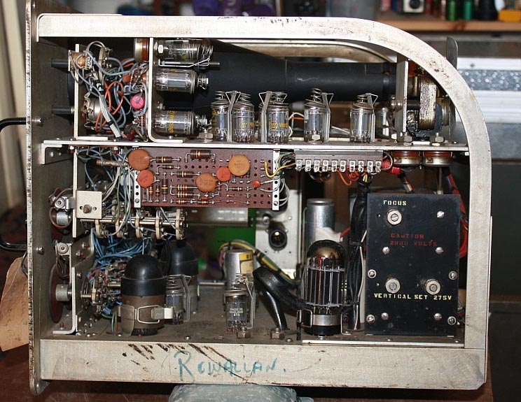
EDO Canada made the model 262A Loran 'A" receiver for the Rediphon company who supplied it in the UK. The name "Rowallan", written on the side of the receiver, refers to the "Lord Rowallan", a 170 foot coal fired steam trawler registered in Grimsby, UK. This vessel worked for many years fishing in North Atlantic and Arctic waters before being scrapped in 1968 when the receiver was removed from the vessel. |
| Model 262A top view. This set uses the Trochotron cold cathode counting tube. There are three of them in the set. | |
 |
Model 262A side view 1 .At one time, EDO Canada
(subsidiary of EDO Corp) was a supplier of electronics to the Canadian
Department of National Defence.
EDO Corporation was an American company which was acquired by ITT Corporation in 2007. EDO designed and manufactured products for defense, intelligence, and commercial markets, and provided related engineering and professional services. It employed 4,000 people worldwide and had revenues of $715 million in 2006. EDO's assets were acquired by ITT Defense Electronics and Services. As of May 2015, these assets are now part of Harris Corporation, and since June 2019 ,L3Harris Technologies. |
 |
Model 262A side view.2 |
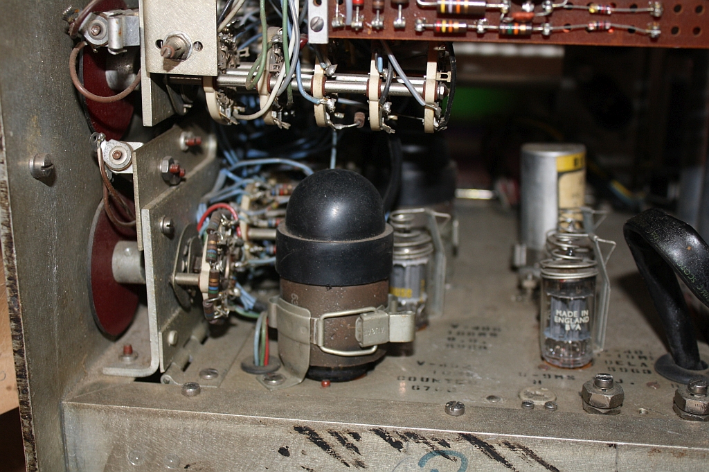 |
Closeup of the Trochotron tube. In a later development, it became known as the "Beam-X Switch" counter tube. Another name was "magnetron beam-switching tube", referring to the derivation from a split-anode magnetron. Trochotrons were used in the UNIVAC 1101 computer, as well as in clocks and frequency counters. |
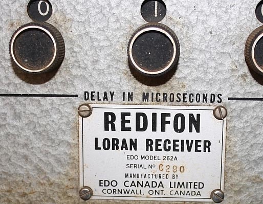 |
Model 262A nameplate |
| Click on any image to enlarge. All photos in this table by Peter G8BBZ. Looking for some operational or technical information for the EDO model 262A. Please contact: jerry.proc@sympatico.ca | |
THE END OF LORAN-AThe accuracy of Loran-A varied according to location, time of day, weather and relative geometry of transmitting stations. Aside from some testing by the USCG, the follow-on system Loran-B, never made it as a commercial system of navigation due to technical problems. It was eventually surpassed by Loran-C which provided longer range, greater accuracy when it first came into operation in 1957. Loran-A was phased out in December 1980 in North America and most of the world by 1985. In 1995, there were still a number of chains operating in China.and Japan and these are listed below.
The Chinese chains began with a '1' and the Japanese chains with a '2'. The ground wave ranged from 650 to 900 nautical miles and the skywave up to 1250 to 1500 nautical miles.
Rate LORAN-A Chain
---- ---------------------------------
1L1 Chengshan Jiao / Shanggulin chain
1L0 Chengshan Jiao / Zhuanghe chain
1L4 Sheyanghe / Chengshan Jiao chain
1L5 Sheyanghe / Gouqishan chain
1S1 Shitang chain
1S2 Tiandashan chain
1S3 Shibeishan / Sanzao Dao chain
1S4 Sanzao Dao / Shibeishan chain
1S6 Longgun chain2S3 Niigata / Matsumae chain
2S4 Niigata / Miho Wan chain
2S5 Tsushima / Miho Wan chain
2S6 Noma Ike / Tsushima chain
2S7 Noma Ike / Gesashi chain
2H5 Miyako / Geshasi chainOne source says that the last holdout was Japan where the plug was pulled on May 9 1997, yet the Admiralty List of Radio Signals of 2000 still lists the Chinese stations.
Loran-A closures came much to the delight of amateur radio operators who had to share their 160 meter band with Loran on a secondary basis for so many years. During that era, amateurs were required to reduce power substantially in the bands 1,800 to 2,000 kHz. In Canada, power levels of 375 watts were permissible during daylight hours and 150 watts at night. Depending on the region, daytime power was 500/200 watts in the United States and 200/50 watts by night.
At the end of the system's life cycle, the development of receivers has spanned right up to the APN-35. The set had been reduced to the size of a shoe box and had automated the process of performing the fix while including ground speed, distance traveled, distance remaining, and ETA.
Other key information about Loran 'A' can be found at the Loran History web site.
REFERENCES:
1) The Journal Of Navigation - Chapter 4; W.F. Blanchard,
Royal Institute of Navigation; Vol 44, No. 3; Sept 1991. Used with permission.
1) Admiralty Manual Of Navigation Vol I; BR45. (1955). Her Majesty's Stationery
Office, London
2) Electronic Communication. (1967). McGraw-Hill. USA
3) USCG web page: http://www.uscg.mil/lantarea/bjc/aton.htm
4) International Maritime Org. web page: www.imo.org/focus/safnav/safenv15.htm
5) Flying Club On-Line web page: http://www.xde.net/flying/links/how_why/gps.htm
6) The ARRL Radio Amateurs Handbook. ARRL, Newington , Conn. 1963.
7) Signals Collection '40-'45 web page: www.qsl.net/pe1ngz
8) Electronic Navigation Systems. Philco-Ford Training Manual. 1967.
9) Special Purpose Navigational Charts and Publications. Defence Maping Agency, Wash. DC.
10) WUN Newsletter: Loran-A Still Active in China. Ary Boender. e-mail: ary(at)luna.nl
11) Elsa Lessard <elsal(at)rogers.com>
12) Public Works Canada http://www.pwgsc.gc.ca/db/text/archives/2002/summer2002/article009-e.html
13) Bill Dietz <bdietz57(at)hotmail.com>
14) Loran A History Site http://www.loran-history.info/loran-A.htm
15) Frank Statham <fstatham(at)telus.net>
16) AN/ANP-4 interior photo: https://arstechnica.com/gadgets/2017/08/radio-navigation-set-to-make-global-return-as-gps-backup-because-cyber
/?fbclid=IwAR3IlYQLgvj5YXxaf_LGUM-rkzNuGotrszUZ8DKzyFgwqKwmJy66UknaPYs
17) Terry Kennedy <tbkenn(at)yahoo.com>
18) Peter G8BBZ g8bbz@g8bbz.org.uk
19) Copilot
July 4/26