 |
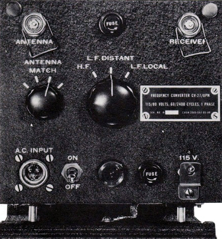
| This is the American version of the CV-27 converter. The nameplate is lacking a manufacturer's name. When the HF/ LF Local switch is in the HF position, the CV27 internals are bypassed completely. (Image courtesy MIT Radiation Laboratory) |
The CV-27 converter allowed Loran 'A' receiver/indicators to receive experimental Loran signals transmitted in the 180 KHz band. Since there was no letter designation assigned to the experimental signalling, it was simply referred to as LF Loran for the duration of the experiment. The converter had a bandwidth from 160 to 195 KHz and in the LF distant position, it provided 10 times amplification. LF local introduced a factor 5 loss to the incoming signal.
|
| This is the American version of the CV-27 converter. The nameplate is lacking a manufacturer's name. When the HF/ LF Local switch is in the HF position, the CV27 internals are bypassed completely. (Image courtesy MIT Radiation Laboratory) |
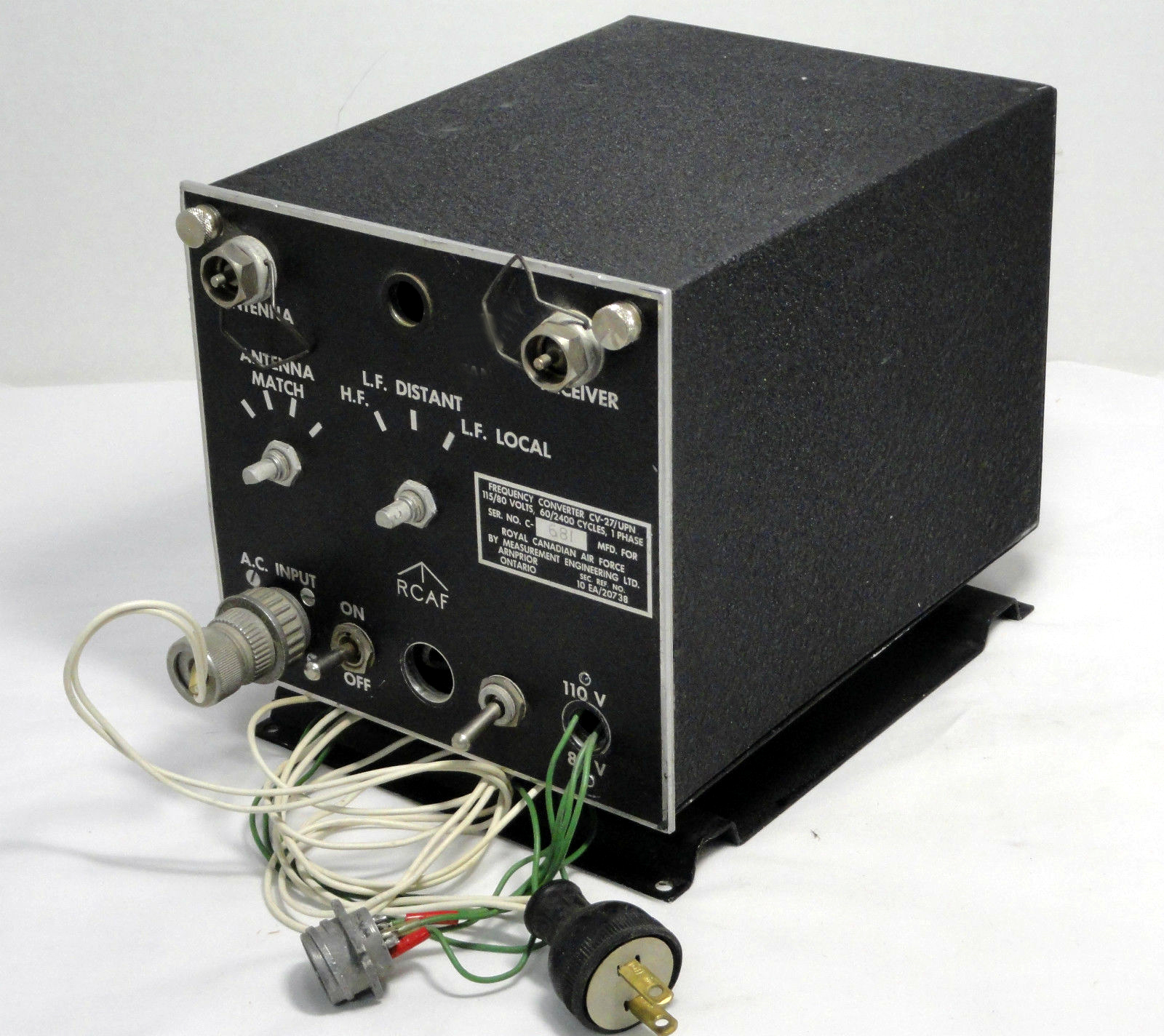 |
| Overall view of the Canadian version of the CV-27 |
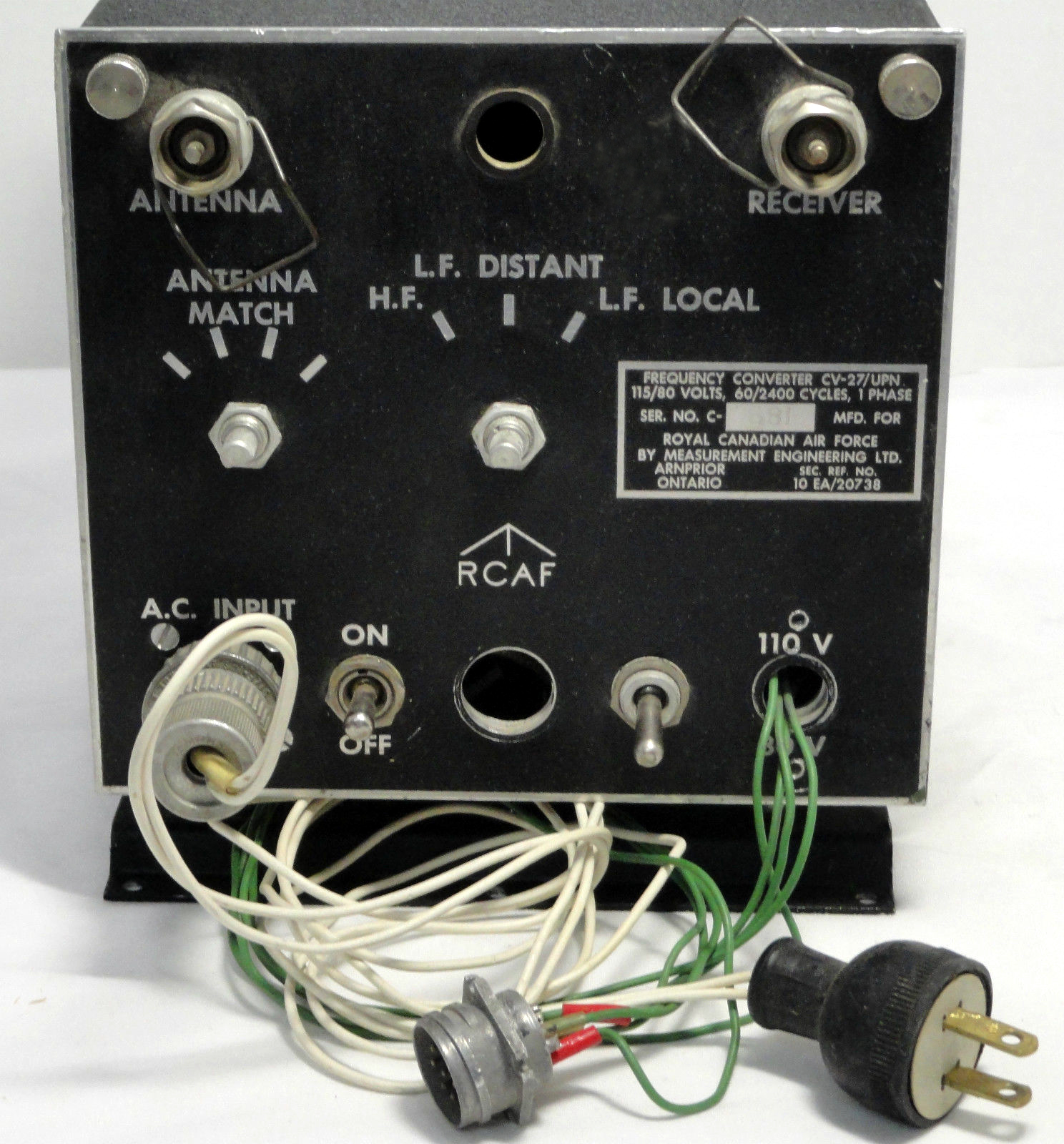 |
| Front panel view. This (modified) Canadian example of the CV-27 is missing knobs and fuses. Otherwise, it appears to be identical to its American counterpart. The purpose of the "RCAF" lettering is not known at this time. |
 |
| Left side view |
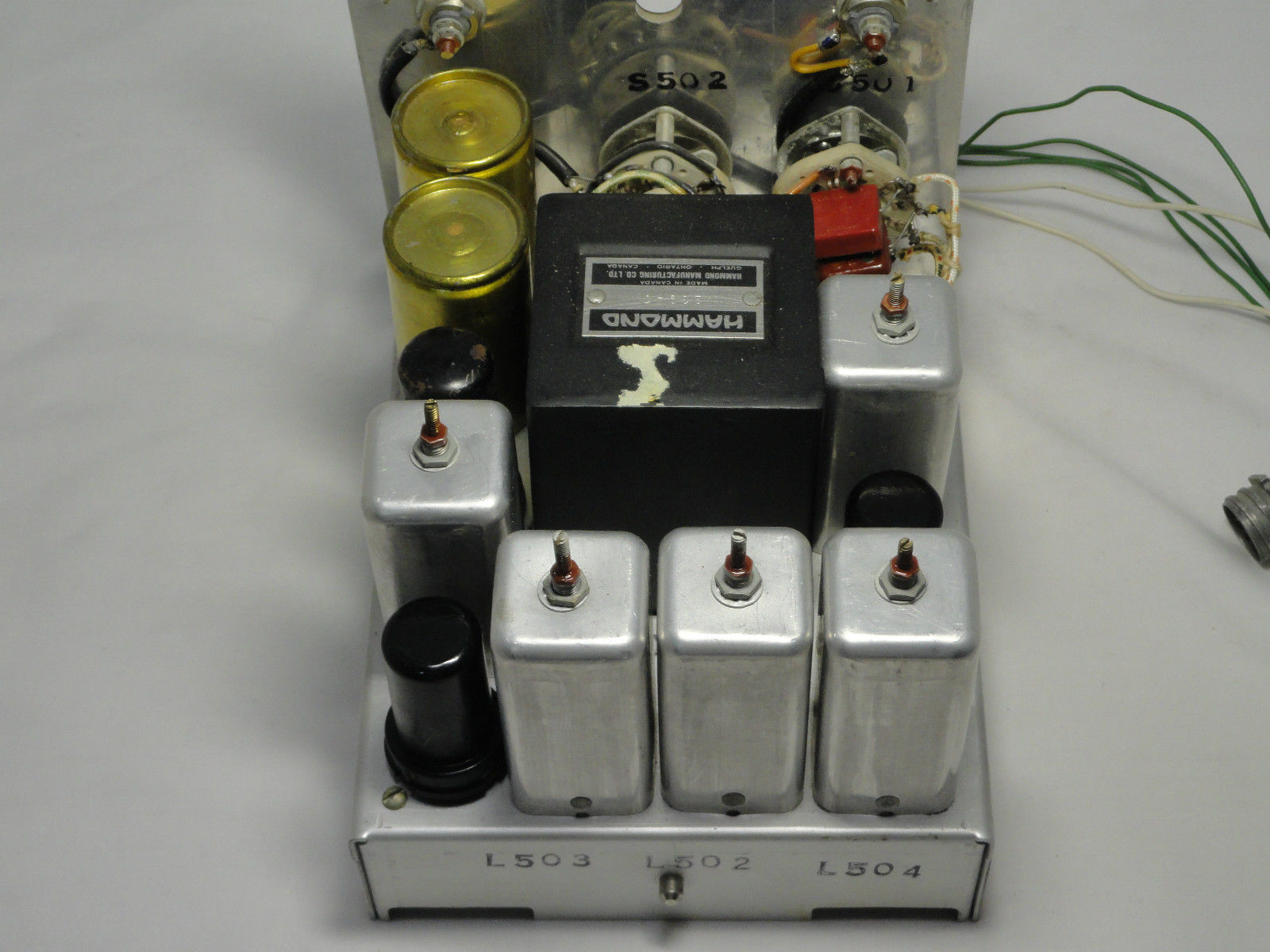 |
| Rear and top views. |
 |
| Right side view |
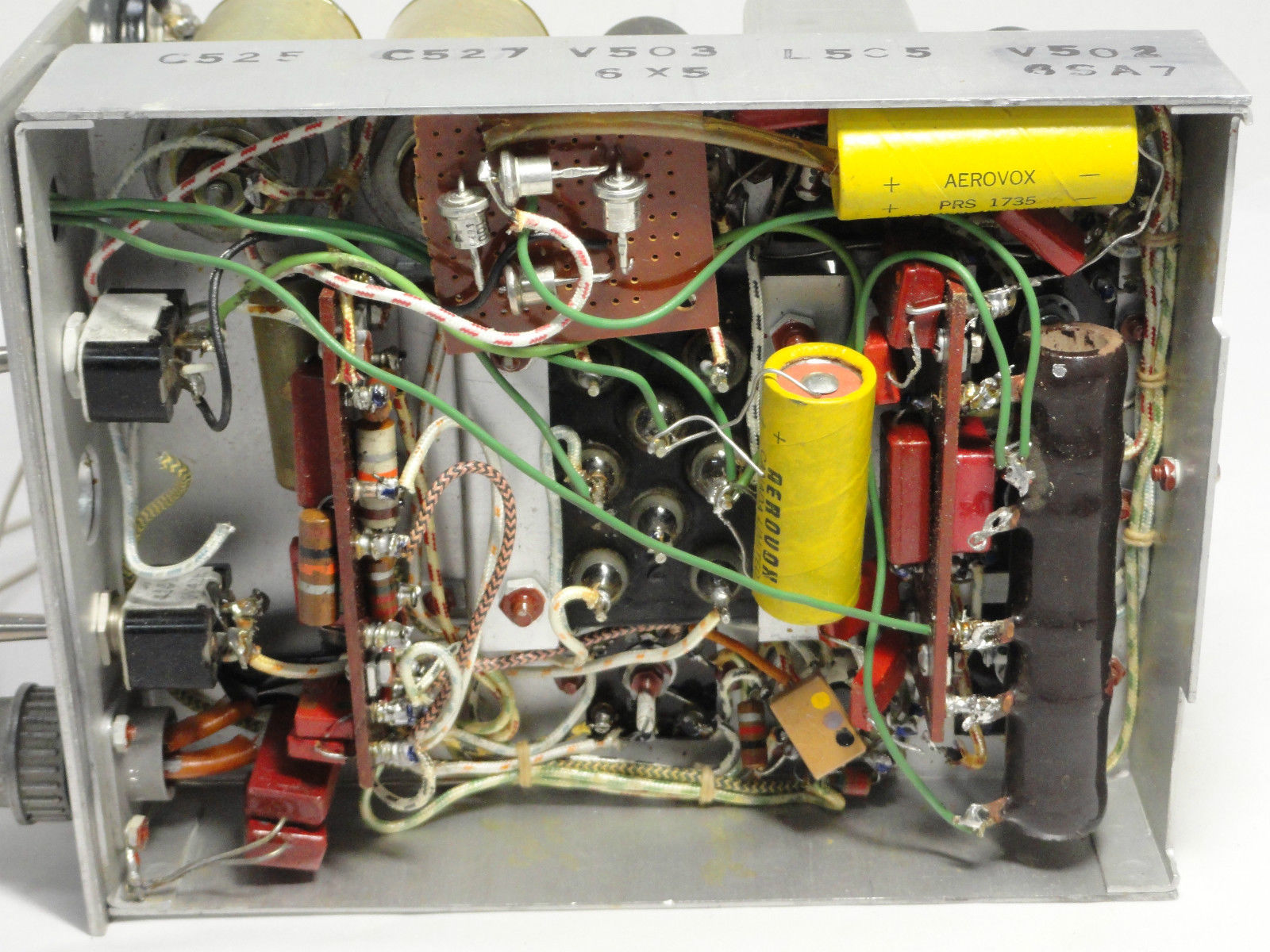 |
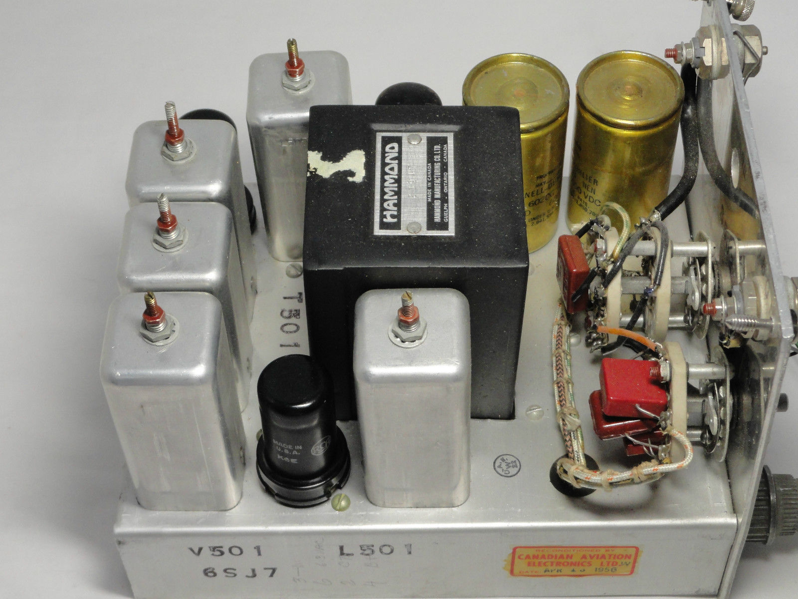
| Bottom view. The four top hat diodes and yellow capacitors do not belong. They are part of someone's modification. |
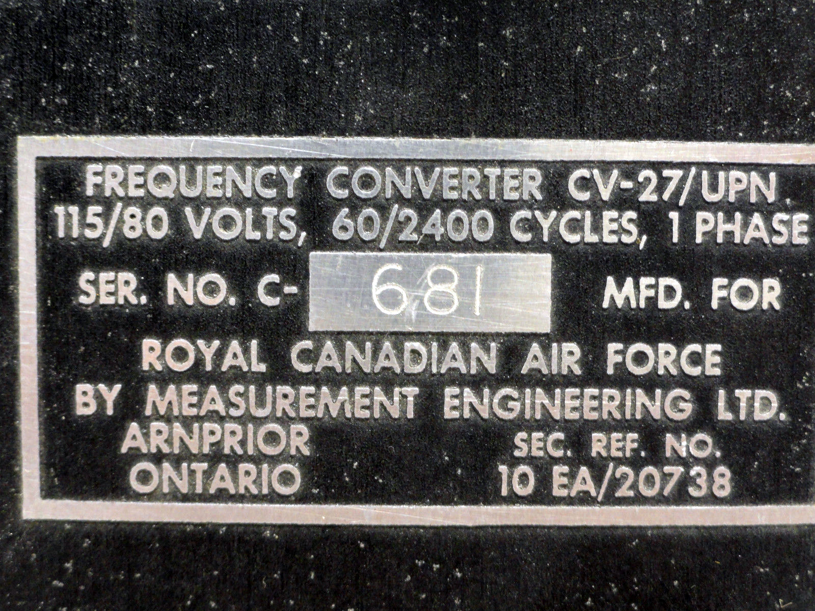 |
| Nameplate |
| All photos in this table via E-bay |
References and Credits:1) John Forster <jfor.backup.email(at)gmail.com>
2) Handbook of Maintenance Instructions for CV-27/UPN dated July 1945
Mar 31/16