 |
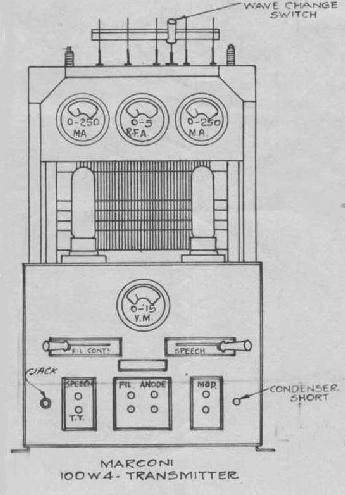
| 100 W4 transmitter. (Courtesy Laval Desbiens via Spectralumni) |
100 W4 Medium Frequency Transmitter SPECIFICATIONS
Modes: CW. MCW and phone
Frequency Range: 800 to 210 metres
Power Output: 100 watts
Frequency Control: Self controlled master oscillator
Circa: 1926GENERAL
A single wavechange switch allows operation on any two frequencies within the band 375 to 500 kHz. For operation in the 300 to 500 meter band, the recommended antenna is the inverted L-type consisting of four 75 foot wires spaced 3 feet apart and 65 feet high. For the companion receiver, Marconi recommended the MST2 Tuner/MSA5 Amplifier combination.
|
| 100 W4 transmitter. (Courtesy Laval Desbiens via Spectralumni) |
ADJUSTMENT AND OPERATION
This explanation was provided my Milton Watts from his hand written notes.
The 100W4 is a two tube medium frequency transmitter with provision for pre-tuning to three frequencies in MF band and for type A1, A2 and A3 emission. For type A1 the two tubes operate as parallel oscillators and for A2 and A3, looking at the set from the front, the left hand tube serves as a oscillator and the right hand tube as a modulator. The oscillator is directly coupled to the antenna and antenna itself is therefore a main part of the oscillator LC circuit. With approximately 200 watts input the output is approximately 100 watts and therefore the efficiency is approximately 50%. (slightly over 55% on CW and somewhat less on RT and TT).
Power Supply
Motor. 1 hp 110 volt DC differential compound provided with a line switch, fuses and hand starter.
Generator. Cumulative compound DC two armature windings. One armature winding terminates at a commutator at one end of the generator to provide from approximately 10 - 15 volts at a maximum 12 amps approximately 150 watts. The other winding terminates at the other end of the generator at a commutator having more and finer segments than at the 12 volt end and has a maximum output of .4 amps at 1000 volts (400 watts). There are two series fields one in the 12 volt circuit and on in the 1000 volt circuit. The generator also is provided with a common 12 volt shunt field in series with which is a hand controlled field rheostat. The motor and generator are coupled together by means of a semi flexible coupling.The main objectives involved in tuning a transmitter are :-
1 - Tuning to desired frequency
2 - Stable operation
3 - Highest efficiency compatible with stable operation.Normally there are four flexible leads running from the wave change switch on top of the transmitter to the main tuning inductance which is about a foot in diameter and has 44 turns of heavy flat copper winding (provision is made for a fifth lead which is only used when a counterpoise is necessary in the antenna system). For each frequency to which the transmitter is to be tuned a set of four detachable jacks is necessary. (Taps for 425 are placed high on the coil and are less accessible then those for 500 and 375. As the wave change switch has only two positions it is necessary to move the flexible leads from the 500 Kc taps to the 375 taps when operation on 375 is required.) The four taps for any one frequency are named in the following order when facing the transmitter from the back and reading from left to right. Left had tap grid; second cathode (ground); third plate; fourth antenna.
To adjust for any desired frequency the following procedure is used:-
1 - Place cathode tap to left of center keeping in mind that enough turns must be left between the cathode tap and the left of the coil to take care of the grid tap (About 10 turns)
2 - Place grid tap to left of cathode tap enough turns so that sufficient regeneration will be assured to cause oscillation (6 or 8 turns). The lower the frequency the more grid turns will be required.
3 - Place plate tap to right of cathode tap (15 or 18 turns). The number of turns between the cathode and plate taps determines the amount of oscillator plate current that will flow when the set is oscillating. On initial adjustments it is therefore desirable to have enough plate turns to hold the plate current to less than normal.
4 - Place antenna tap a few turns to right of plate tap. The number of turns between cathode and antenna determines the frequency of oscillation and radiation. The more turns the lower the frequency and visa versa.When connections to inductance are securely made check wave change switch for proper position, place mode of operation switch in CW position, close line switch and start motor (hand starter). Place filament rheostat at center of travel and with filament switch closed adjust generator field rheostat so filament voltmeter read 10 volts. Allow 30 seconds or more for tubes to warm up and close anode and aerial changeover switch which closes magnetic switch and applied H.T. to set. If initial adjustments have been properly made set should now oscillate when CW key is closed and meter readings may be observed and the frequency checked with a wave meter. A showing of antenna current when the key is pressed indicates the set is oscillating. If the set is oscillating the final adjustments may now be made to obtain the 3 objectives outlined at the beginning of this article.
Note - If adjustments are such that the set will not oscillate, either when the AC switch or CW key is closed the plate meters will be driven right across their scale and their may be heavy sparking at the tube bases or other places and the 4 amp HT fuse will blow. This is due to their being no bias if the set does not oscillate and indicates there is not sufficient turns between the cathode and grid taps (regeneration) providing all connections, antenna etc are in proper working shape. If set oscillates when it is first turned on the antenna tap is varied to obtain the proper frequency, the plate tap is varied to obtain the desired oscillator plate current and the grid tap is varied to obtain the highest efficiency (highest antenna current) compatible with stable operation. If too much regeneration is provided the antenna current will not be what it should be for any given input and there may be excessive sparking at the key contacts when the set is keyed in which case the grid tap should be moved closer to the cathode tap. The grid tap may be moved towards the cathode until there are signs of instability and then fastened one turn further away from cathode than this point. The proper placement of the antennae tap is determined by means of a freq. or wave meter.
Normal operating meter readings for the 100W4 are as follows:
| FILAMENT |
|
Antenna Current | Condition | |
| V1 | V2 | |||
| 10 volts | 0 | 0 | 0 | CW key up |
| 10 volts | 100 ma | 100 ma | 3.25 Amps | CW key down |
| 10 volts | 150 ma | 75 ma | 2.75 Amps | ICW key up |
| 10 volts | 140 ma | 40 ma | 3.00 Amps | ICW key down |
Notes:1) UV 211 Filament Voltage - 10 volts @ 3.25 amps
2) If longer range is necessary then can be obtained with the transmitter operating on the above settings, additional output may be obtained for CW operation only by adjusting the plate tap when in the CW position to raise V1 and V2 plate current to 175 ma each when the key is pressed for CW. With this adjustment, the transmitter must not be switched to speech or TT.
 |
100W4
schematic. (Provided by Bruce MacMillan)
|
 |
Handrawn 100W4 transmitter schematic. This was one of the skills required to obtain a radio operator's certificate in the far past but now a lost art. (Hand drawn by Milton Watts) |
 |
This diagram shows all the interconnections for the Canadian Marconi 100W4 transmitter with a pairing to a MST-2 tuner and MSA-5 amplifier. Click on thumbnail to enlarge. (Image courtesy Denis Couillard) |
Milton Watts adds this comment. "I drew these in radio school in Calgary 1949/50. We had to be able to describe the circuit and all it's functions. Our instructor advised us we would probably never use the equipment but the knowledge was required in order to pass the government test for a second class commercial ticket. Some of the equipment was in the class room, but the only one I remember is the 100W4. It was a marvel to behold when it was fired up and more spectacularly when shut down and the safety switch pushed to discharge the capacitors".Al Miller, VE7KC, operated the 100W4. He recalls " The Marconi 100W4 used a pair of 211 tubes and could be operated on CW, phone and ICW . It was a horrible thing because when keying it, you got RF burns on your fingers from the key.
When I was living and working in Victoria in 1938-9, station CJVI was using a converted 100W4 for a transmitter with an outboard separate modulator. Frequency wise, it was very unstable and just about drove the DOT monitoring station crazy. They changed to commercial broadcast equipment while I was there".
| 100W4 Operators Manual - PDF (Courtesy Spectralumni via Laval Desbiens) |
Contributors and Credits:1) Milton Watts <wattsma6(at)telus.net>
2) Al Miller <almiller73(at)shaw.ca>
3) Spectralumni http://www.spectralumni.ca
4) Laval Desbiens < desbienslaval(at)gmail.com>
5) Bruce MacMillan <radio(at)telus.net>
6) Denis Couillard Ultra Electronics <Denis.Couillard(at)ultra-TCS.com>\
7) The Early Development of Radio in Canada 1901-1930 by Robert Murray. Page 34
Jul 23/1