 |
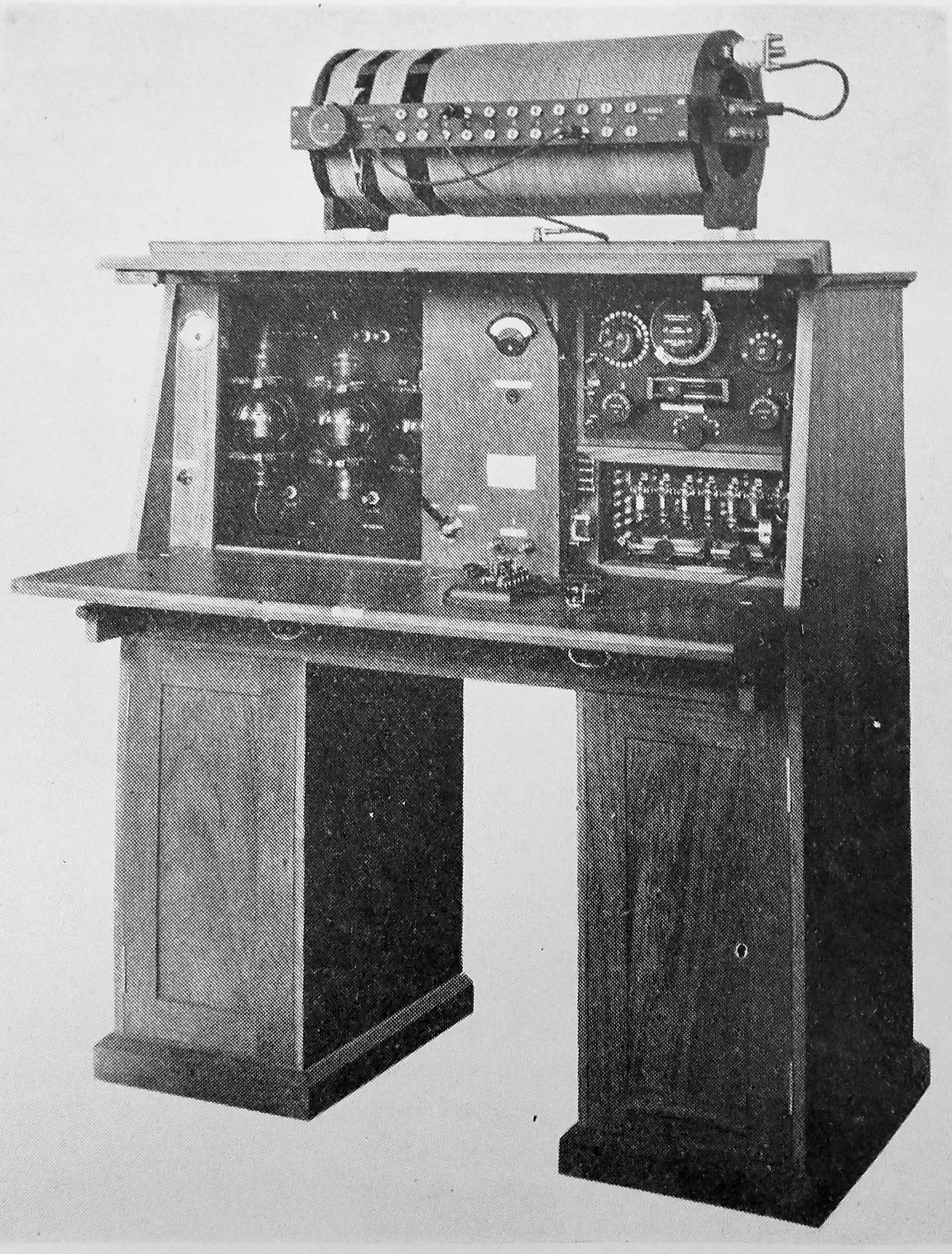
| 1,5 kw Cabinet type transmitter. The transmitter is divided into two parts. The transmitting valves were mounted on a panel at the left while the receiving components were situated on the right side. The transmitting tuning inductance and the reaction coil are supported by insulators mounted to the top of the cabinet. At the right top is the Marconi (UK) type 70 tuner with the type 55 detector amplifier below it. (Image courtesy HIT) |
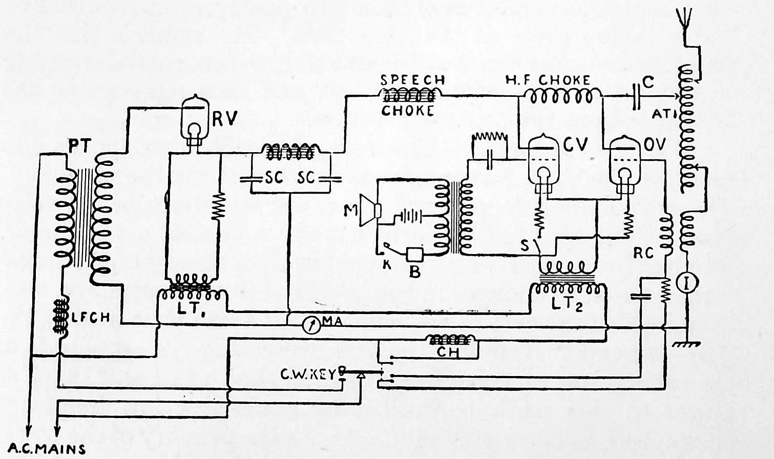 |
| A
simplified schematic of the transmitter portion of the cabinet style transmitter.
The highlights of this circuit are:
Valve RV provides half wave rectification. In CW mode, only valve OVA is used as the oscilator .Valve CV gets disconnected from the filament lighting transformer FOR ICW operation, valve CV is flashed up in addition to the oscillator valve OV.. When wireless telephony mode is used, the microphone' 'M'' and the transformer that its connected to , modulate control valve CV. (Schematic courtesy HTI). |
| This is the antenna changeover switch between the receiver and the transmitter, (Courtesy HTI). |
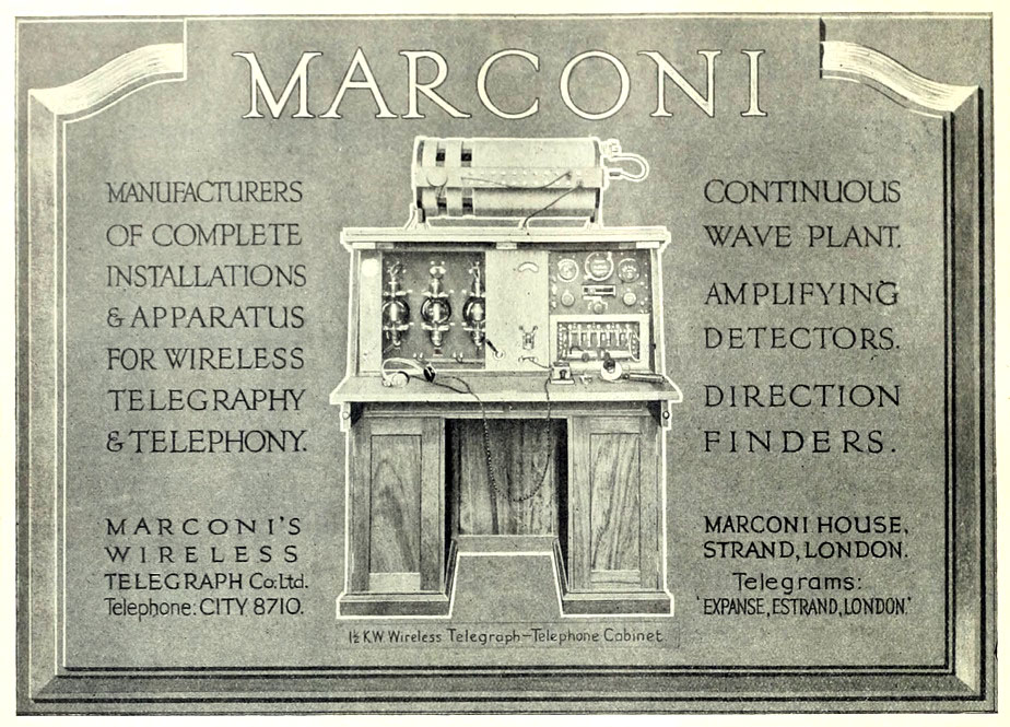 |
| This 1.5 kw set was likely imported from Marconi UK by Canadian Marconi for sale in the Canadian marketplace. Not sure about the source of this ad. It may have have been published in Yearbook of Wireless Telegraphy 1920 (Submitted by Lewis Bodkin) |