2846B Receiver


SPECIFICATIONS

Frequency Range: 100 to 500 KHz
Use: Commercial marine receiver
Circa: Likely made after 1916 and before 1922.
 

2846B_02_front.jpg
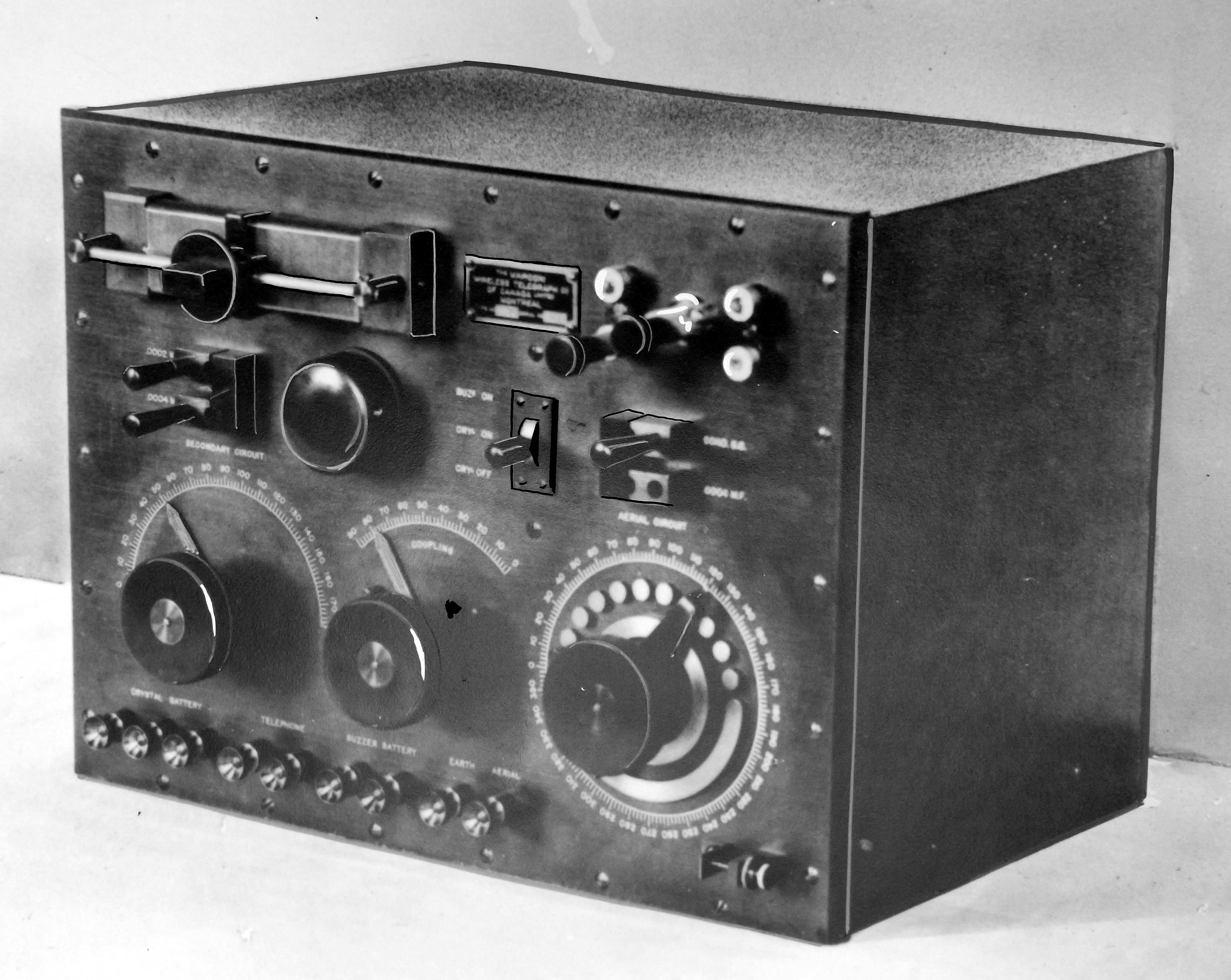
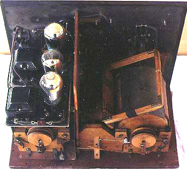
This is an unmodified example of the 2846B held by the Hammond Radio Museum.  In the upper right corner there are four switch selectable carborundom crystals. Switching the crystals was done by rotating the pressure point arm to the desired position. The lower right corner has a spark gap attached to the receiver input. Its purpose was to protect the receiver from static charges which could build up as a result of wind gusts blowing across the antenna wire. This would be the case if the 2846 was fitted aboard a ship. 

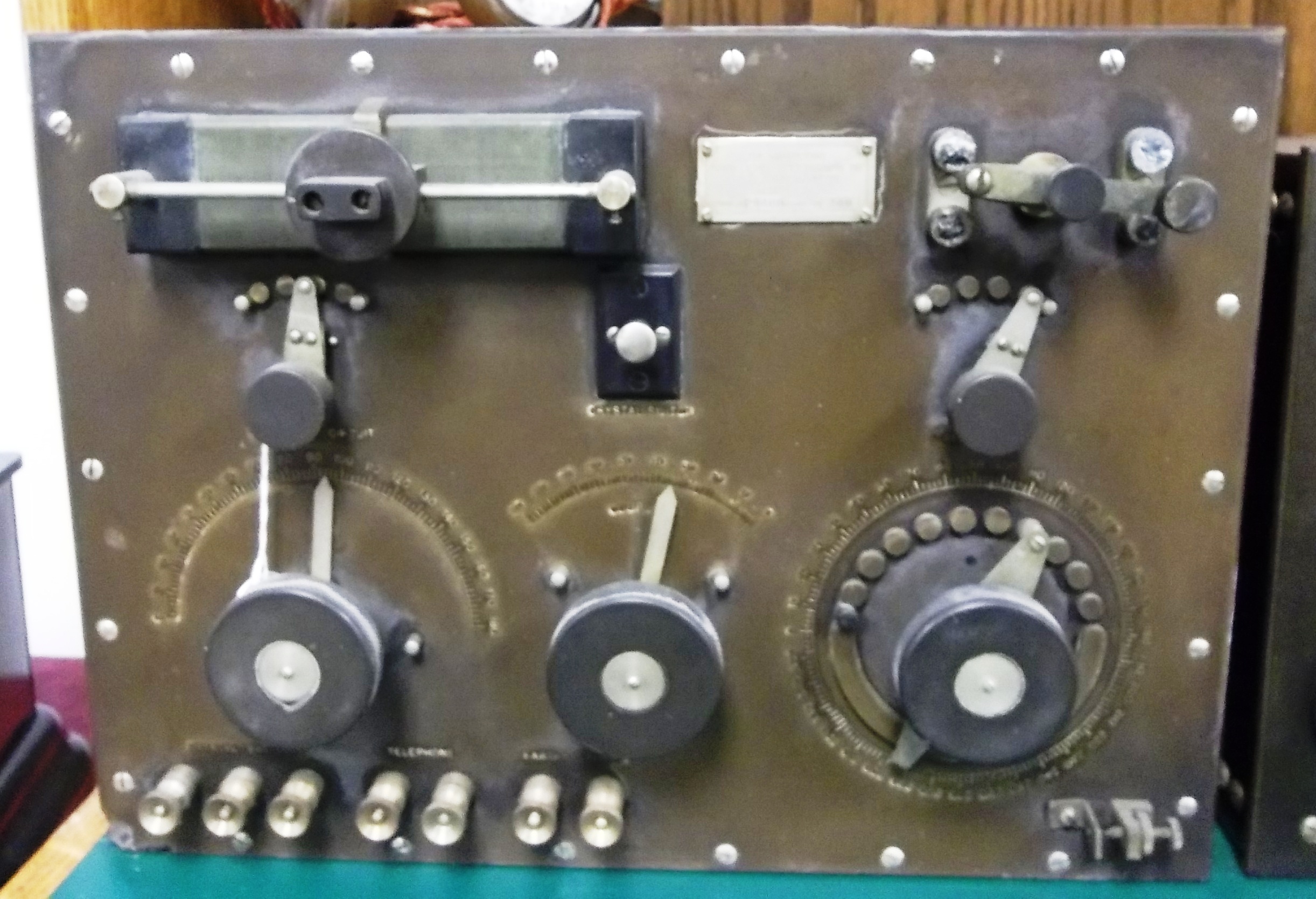
Just to the left and below the placard is an automotive type, pull switch. Note the differences in the binding posts between this receiver and the one below. This example lacks the buzzer. 

The front panel was made from a material which was called " Hard Rubber" in the trade. Due to the type of materials used in the fabrication of the front panel, discolouration is in evidence over time. Exposure to light makes the panel turn from black to brown from oxidation.  The shade of brown that it becomes is proportional to the length of time the receiver has been exposed to light. There is evidence of this in the photo. (Hammond Radio Museum photo) 

2846b_10.jpg
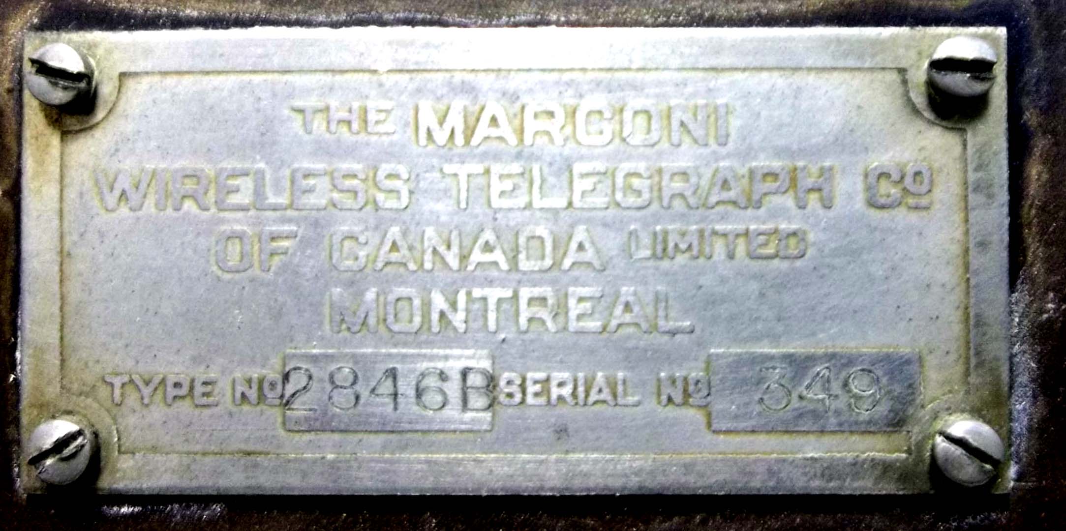
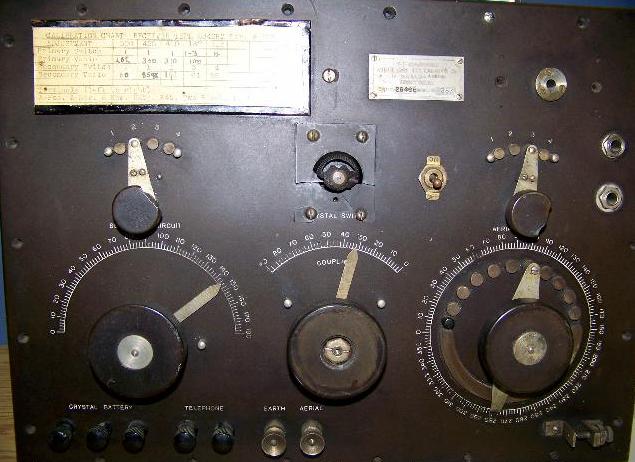
Nameplate . (Photo  by  Lewis Bodkin) 


2846b_001.JPG
2846b_002.JPG
2846b_003.JPG
2846b_004.JPG
2846b_005.JPG
All 2846B internal photos in this table by Noreen Irwin VE3AQZ, Curator, Hammond Radio Museum . 
 
2846_10a.jpg
In  this example of the 2846B, the black metal can, located at centre left of the front panel, is a buzzer. The purpose of the buzzer was to test the continuity of the carborundom crystal detectors. Click on image to enlarge . (Image by Lewis Bodkin) 
MODIFIED 2846B EXAMPLES
2846b_receiver1.jpg
This 2846B  receiver has been modified. This example lacks the buzzer  The modified receiver does not have the crystal switch on it. The crystal  switch was replaced with a filament rheostat .(Photo via the former Le Musée Québecois de la Radio)
2846b_receiver3.jpg
This particular example of a  type 2846B was originally designed to use a  crystal detector. In 1926 it was modified to use three vacuum tubes and a Canadian Marconi  M 4-1 audio transformer.  (Photo via Le Musée Québecois de la Radio) 
2846b_rear.jpg
Rear view of a modofied.2846B receiver. (Photo by André Kirouac)
i/trasnsformer_m4I.jpg
A closer view of the Canadian Marconi  M 4-1 audio transformer used in the 1926 modification. Two M4-I transformers were added as part of the modification.  (From Radio Magazine, July 1926)

Contributors and Credits:

1)  Le Musée Québecois de la Radio - Jacques Hamel, VE2DJQ
2)  Lewis Bodkin  <05bodkin555(at)gmail,com>
3) Handbook of Technical Instruction for Wireless Telegraphists by J.C. Hawkhead  1925
4) Noreen Irwin VE3AQZ, Curator, Hammond Radio Museum .
 

Back to Equipment Listing


Feb 8/22