 |
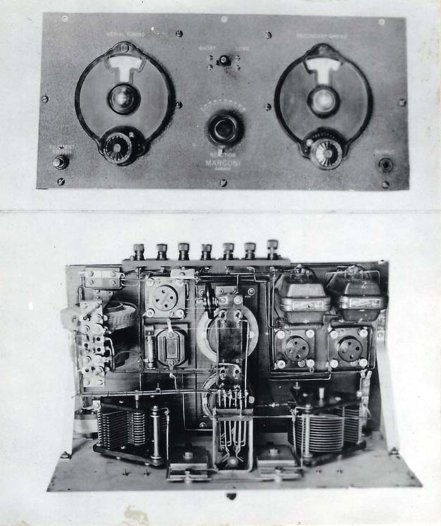
| Front and top views of the 3V-DR-3 receiver. Note that the tubes are missing. |
 |
| Front page of manual as produced by the Department of Marine, Radio Branch. |
3V-DR-3 Beacon Receiver SPECIFICATIONS
Frequency Range: 500 to 730 metres and 2,400 to 3,000 metres
Use: Beacon station receiver
Circa: 1930This extract was provided from the operating manual:
"At the bottom left of the panel is located the filament switch plunger which must
be pulled out to put the set in operation. Always push the plunger in after using the
receiver. At the bottom right of the panel, the phone jack, marked "output", is located.
The head-phones should be plugged into this jack. At the top centre of the panel is
located the range switch. When this switch is in the "short" position the receiver will
function from 500 to 730 metres, and in the "long" position, it gives a wavelength range from
2,400 to 3,000 metres, The reaction is controlled by the knob in the centre of the panel,
while the aerial tuning is controlled by the left hand dial, and secondary tuning by the
right hand dial.The aerial tuning may vary greatly on different stations and the Secondary tuning
will vary slightly, But on a standard aerial, the Secondary tuning dial for reception of
NAA (Arlington) time signal should be set at approximately 36 with the range switch
in the "long" position. The aerial tuning and reaction controls may be in the neighbour
hood of 55 and 40 respectively, but these adjustment may vary greatly according to local
conditions. Arlington should be received at. good volume by all East Coast and Great
Lakes Stations, and over the entire length of its two ranges the receiver should be found
sensitive and easily controlled.The battery connections arc made to suitably engraved binding-posts at the back
of the receiver. The receiver is intended to use UX 201 B tubes with an A battery of 6 Volts. The
B battery should consist of two 45 Volt blocks"HISTORIC DATA
In 1868, one year after Confederation, the Canadian federal government established the Department of Marine and Fisheries. This department assumed responsibility for marine affairs, including the operation of government vessels and for various elements of marine infrastructure (aids to navigation, lifesaving stations, canals and waterways, marine regulatory bodies and supporting shore infrastructure). In 1936, responsibility for marine transportation shifted to the Department of Transport.
By the 1940s, many organizations and communities pressed the government to form a national coast guard. Ocean commerce expanded tremendously, culminating, with the opening of the St. Lawrence Seaway in 1958. The Canadian Coast Guard was officially created by the Honourable Leon Balcer, the then Minister of Transport on January 26, 1962.
Frank Statham provides the reason for having time tick receiver on a sequenced radio beacon station, although the name may say it all. "Ideally there would be two or three sequenced beacons in a small geographical area, for instance scattered along the Juan de Fuca Strait, and a couple on the American side and a couple on the Canadian side off the Strait. Each beacon would radiate on the same frequency in its time slot, while the others remained silent. In the case of four beacons, it would take four minutes to run a complete cycle. Timing was critical, otherwise two beacons would be radiating at the same time. This arrangement provided an efficient use of spectrum space in the beacon band (200-400 kHz) which was also shared with aeronautical beacons. Of course, each beacon also transmitted its Morse identifier to avoid any confusion. The light keeper was responsible for ensuring the clocks were correctly set".
|
| Front and top views of the 3V-DR-3 receiver. Note that the tubes are missing. |
|
| Front page of manual as produced by the Department of Marine, Radio Branch. |
 |
3V-Dr-3 schematic. Click on thumbnail to enlarge. |
Contributors and Credits:1) Frank Statham [f_statham(at)shaw.ca]
2) 3V-DR-3 Operators Manual
Dec 14/14