 |
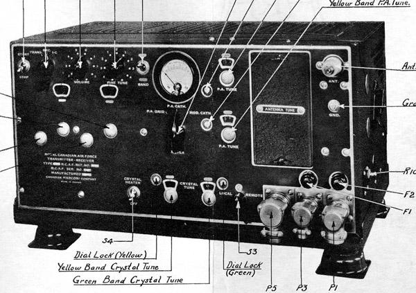
| Front |
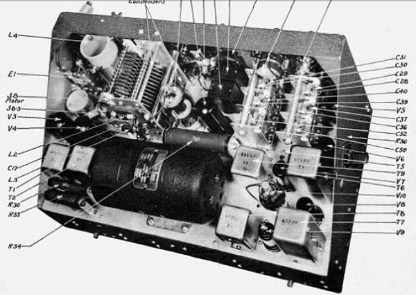 |
| Top view of chassis |
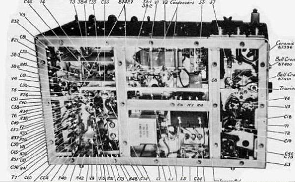 |
| Bottom view of chassis |
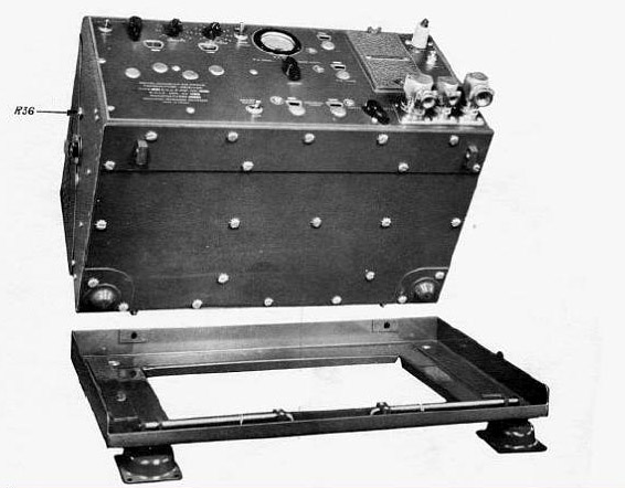 |
| Bottom view and cradle |
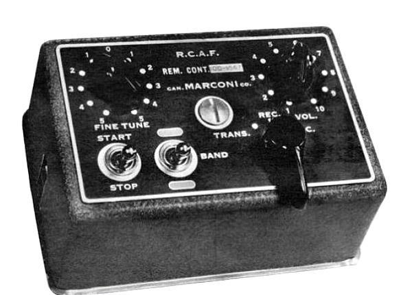 |
| Remote Control Head |
| All images in this table courtesy Canadian Marconi |
ATR-5 Transmitter Receiver SPECIFICATIONS
Mode: AM only
Frequency Range : 3 to 6.3 MHz
Power Output: 16 watts with 12.2 VDC input; 22 watts with 14.6 VDC input
Frequency Control: 2 crystal controlled channels.
Circa: 1940
Weight: 43 pounds
Dimensions: 20" x 11.031" x 11.375 H
RCAF Ref: 10D-1546
Comment: Made for the RCAF. It is a very different radio than the ATR-5 used by the R.A.A.F. in Boomerang aircraft.Current consumption: See table below
Input voltage On Receive On Transmit 11.0 VDC 8.3 amps 13.5 amps 12.2 VDC 9.0 amps 15.0 amps 14.5 VDC 10.5 amps 18.0 amps
|
| Front |
|
| Top view of chassis |
|
| Bottom view of chassis |
|
| Bottom view and cradle |
|
| Remote Control Head |
| All images in this table courtesy Canadian Marconi |
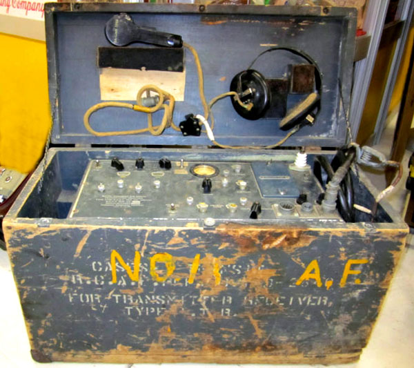 |
| ATR-5 in protective case. |
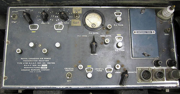 |
| ATR-5 front panel. |
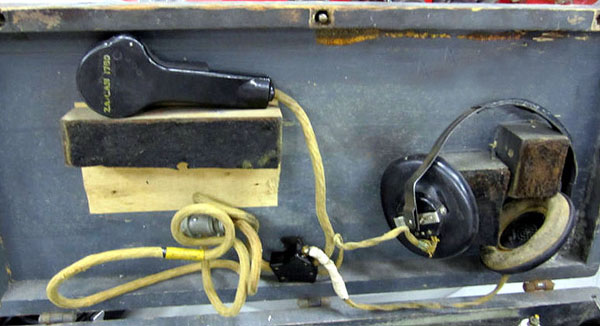 |
| Shipping case lid showing headphones and C3 microphone. |
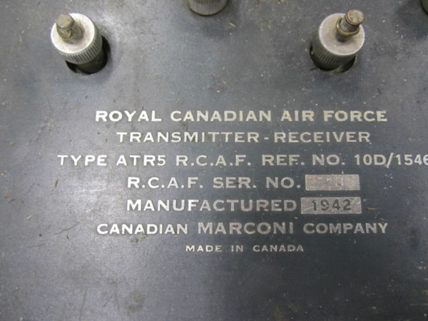 |
| Typical nameplate data. |
| All photos in this table via E-bay. |
\
| Transmitter schematic PDF (left ) |
| Transmitter schematic PDF (right) |
| Receiver schematic PDF |
| ATR-5 Manual |
| Missing page 15 from manual |
| For a complete manual, download everything in this table. |
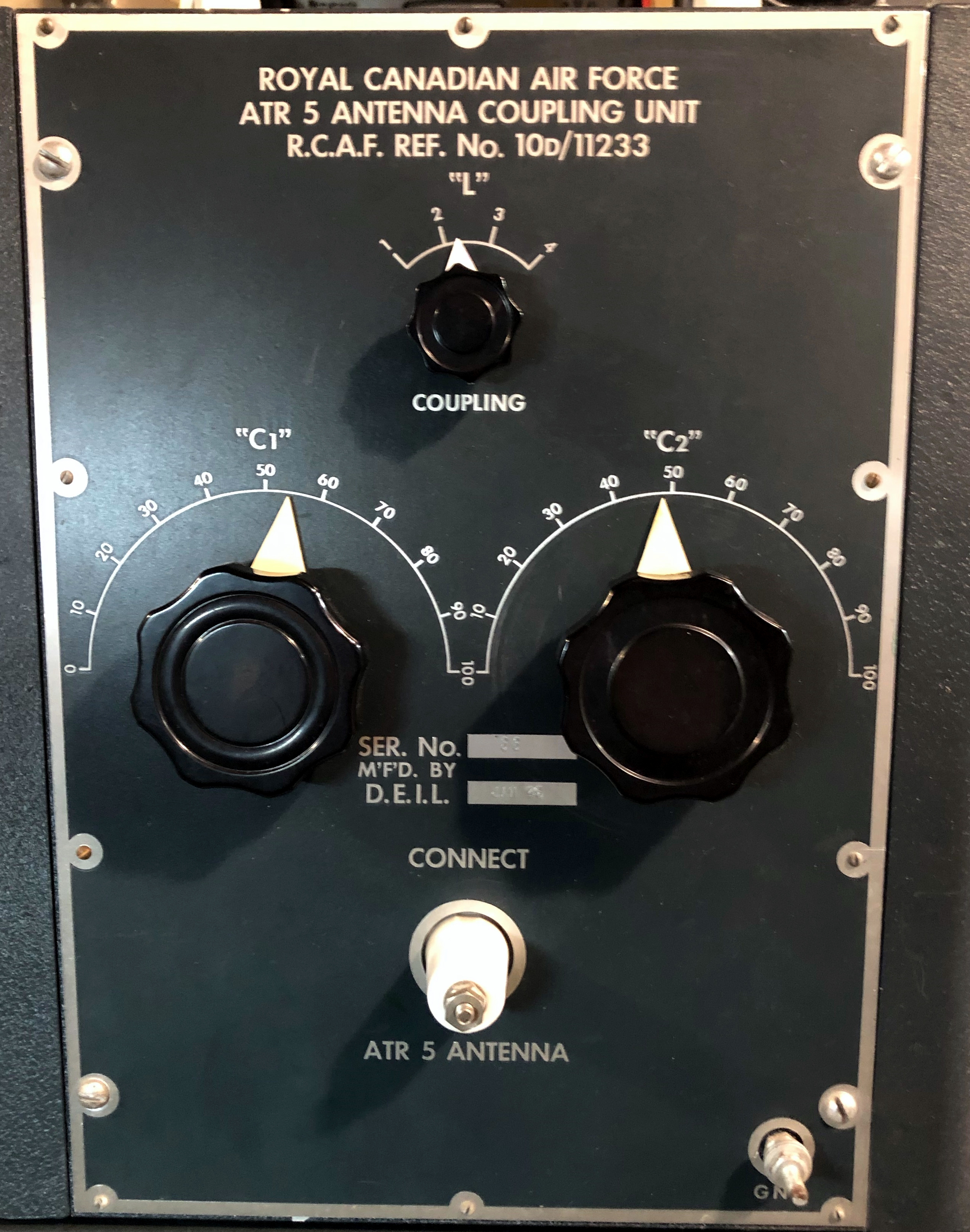 |
| ATR-5 Antenna Tuning Unit 10D/ 11233. The RCAF opted to procure this tuner from D.E.I.L. and not Canadian Marconi . The initials stand for Dominion Electrohome Industries Limited , This is serial number 66 and was made in January 1945. |
 |
| ATR-5 Antenna Tuning Unit schematic. It was affixed to the top of the unit and it looks like it has the function of a BALUN. A BALUN is a device for converting a BALanced line into an UNbalanced transmission line and vice versa. It also matches different transmission line impedances. |
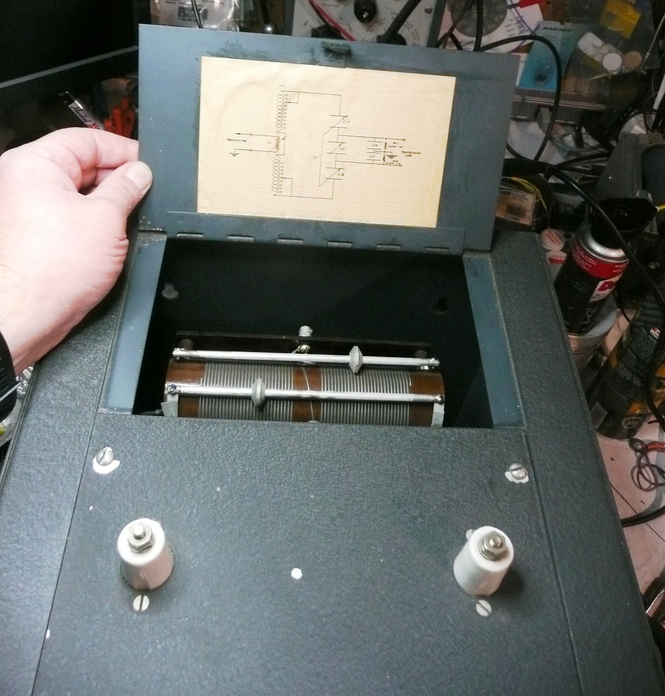 |
| ATR-5 Antenna Tuning Unit . The output feedthrough inductors are positioned at the top front of the cabinet. Behind them is the flap which bears the schematic. The two roller wheels do not have any controls. They are pre-adjusted by rotating the wheels by hand. |
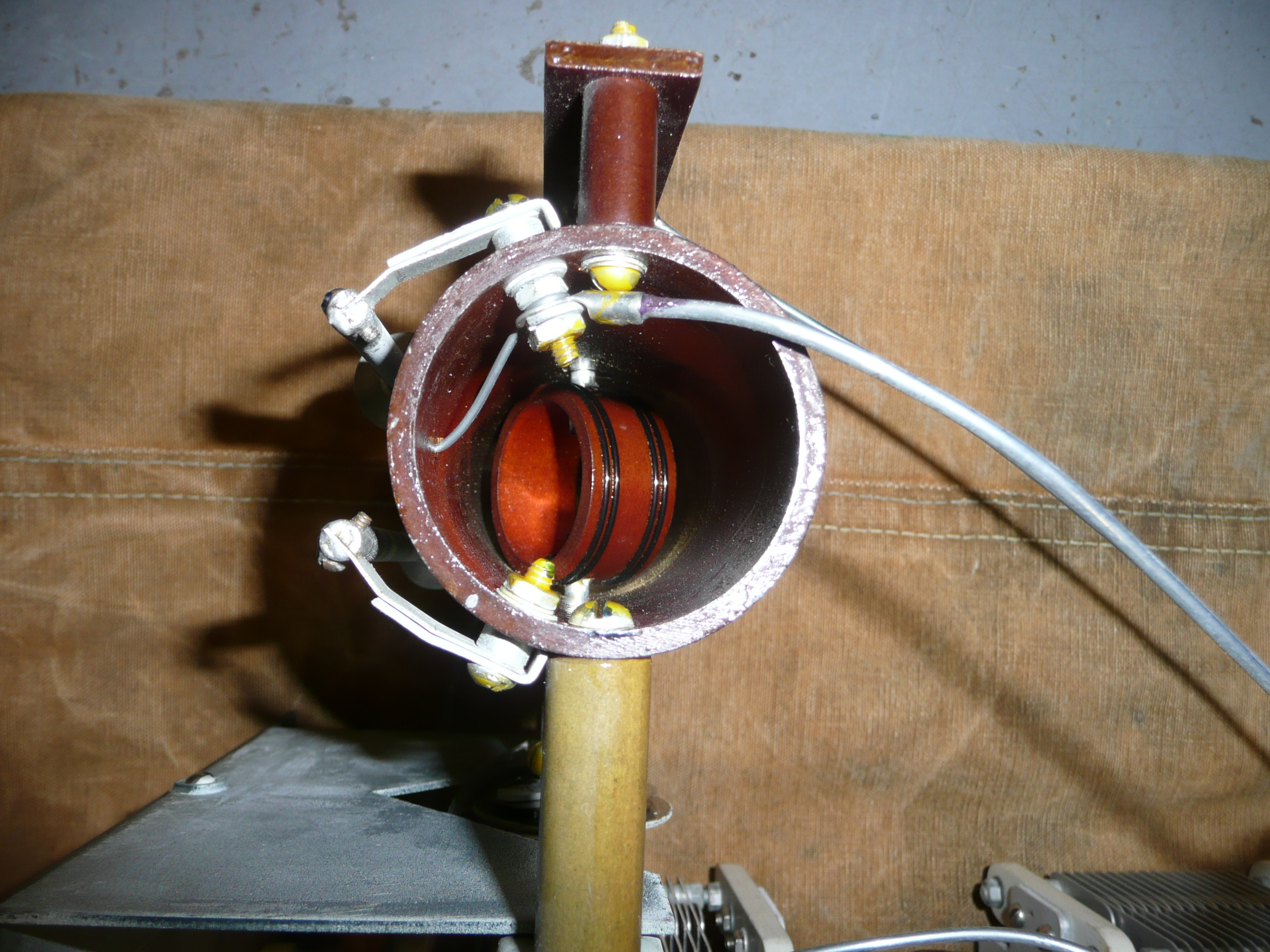 |
| ATR-5 Antenna Tuning Unit - Detailed view of the variometer coil L1. It does not tune continuously. Rather, it has four positions controlled by a detent. The control for the variomenter is the one labelled Coupling . |
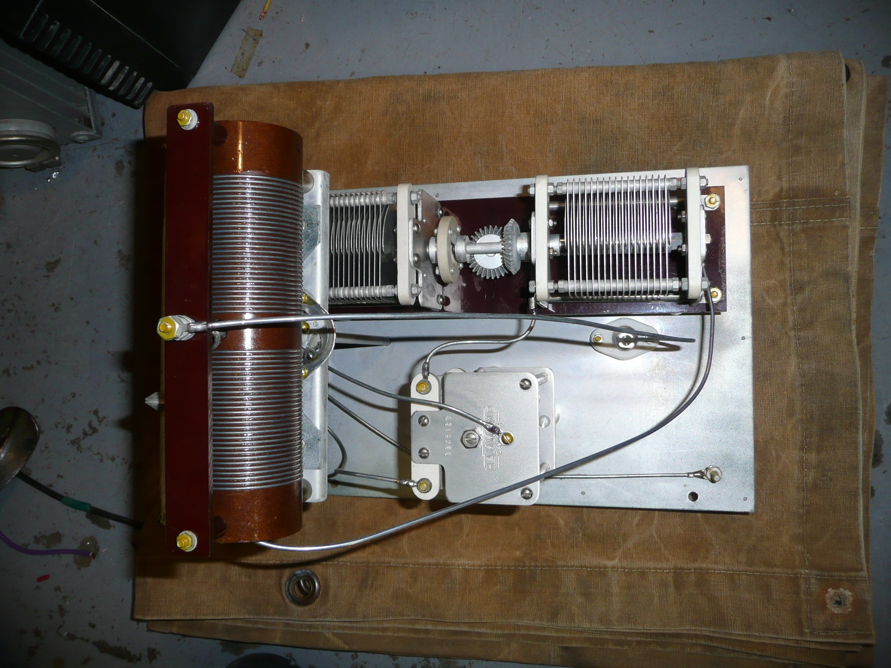 |
| ATR-5 Antenna Tuning Unit - Bottom view. |
 |
| ATR-5 Antenna Tuning Unit -= Left side view. |
| All photos in this table by Jason Ingraham |
Contributors and Credits:1) Bruce MacMillan <bruce_macmillan(at)telus.net>
2) Meir-WF2U <wf2u(at)ws19ops.com> for the ATR-5 manual
3) Tom Brent <tgb(at)telus.net> for the ATR-5 schematics
4( Jason Ingraham [ve1pye9(at)bellaliant.net]
Dec 14/21