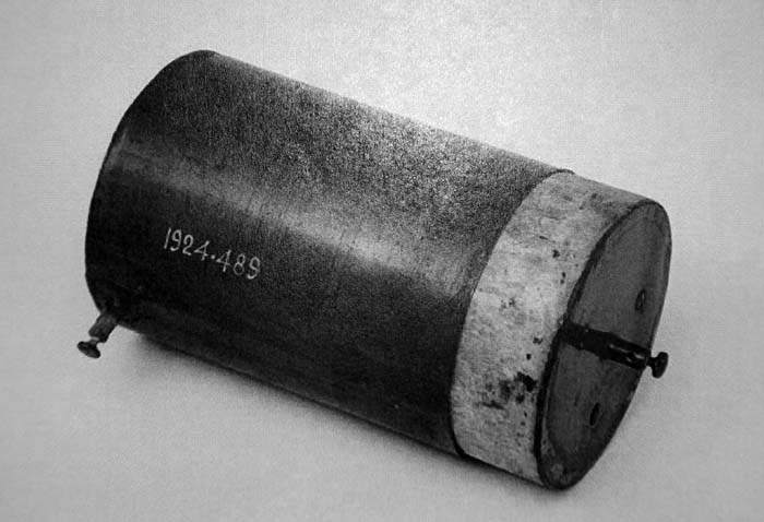
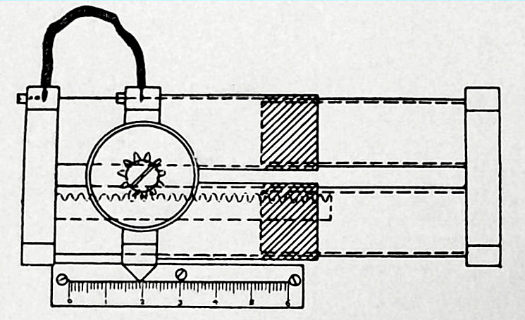
BILLI  CONDENSER

The Billi condenser was the first adjustable receiving condenser used for tuning the aerial circuit in very early receivers. One type consisted of a coil of wire wound over an ebonite tube in which there was a thin sliding cylinder of brass. The operator could then adjust the position of the brass cylinder to achieve the desired capacity. The brass tube was connected to a handle which had a wooden knob at its end.  The operator would grasp the knob and move it back and forth to make an adjustment. An experimental version was used by Marconi in his transatlantic transmission in December 1901; a full production version was brought into use in 1903 or early 1904. It is so named because its capacity is in the order of a billifarad. One billifarad = 1 millimicrofarad or 10^-9 farad.

There are at least two types of Billi condensers. One version is the metallic sleeve in a coil described above and the rack and pinion version shown below.

billi_condenser1.jpg
This is a rack and pinion type of Billi condenser. Two brass tubes slide over thin ebonite tubes inside which are brass plugs. The brass tubes and plugs are the conductors, and the ebonite is the dielectric. The capacity of course depends on the area of the opposing metallic surfaces and the thickness of the ebonite. The active portion  is shaded in this diagram.

For purposes of adjusting the capacitance, the tubes are given a quick movement by means of a rack and pinion fitting. One and a half turns of the milled ebonite head on the stem of the pinion carries the tubes the full length of  travel which is six centimetres . For calibrating the condenser, the tubes carry a brass index and an ivorine scale of centimetres is fixed on the base below. The minimum  and maximum capacitance of such a condenser is .00002 µf and .00045 .µf respectively.  (Extract from Handbook of Technical Instruction For Wireless Telegraphists) .


billi_condenser2_100_0513.jpg
This type of Billi condenser consisted of a coil of wire wound over an ebonite tube in which there was a thin sliding cylinder of brass. The operator could then adjust the position of the brass cylinder to achieve the desired capacity. The brass tube was connected to a handle which had a wooden knob at its end.  The operator would grasp the knob and move it back and forth to make an adjustment.(Photo provided by Lewis Bodkin). 


Contributors and Credits:
.
1)  Lewis Bodkin  <05bodkin555(at)gmail,com>
2) https://www.mhs.ox.ac.uk/marconi/collection/glossary.php\
3) Handbook of Technical Instruction For Wireless Telegraphist

3
Back to Old Components


Mar 27/18