 |
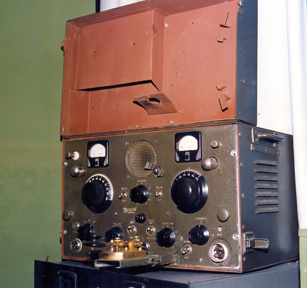
| This CD-12 is held by the C&E Museum in Kingston, Ontario. (Photo by Jerry Proc) |
CD-12 Transmitter-Receiver
Except for differences in frequency control, the CD-12 was the version of the FR-12 built for the Canadian Army. Both the CD-12 and the FR-12 came with a swing-down key attached to the front panel. In addition, the CD-12 had an accessories lid. Each set transmits in the 2 to 4 MHz band at a 15 watt power level on CW and lower power levels on MCW and Phone. The CD-12 could also receive the 300 to 600 KHZ band plus 600 to 3800 KHz.From the manual , CD as in CD-12 means Coastal Defence.
|
| This CD-12 is held by the C&E Museum in Kingston, Ontario. (Photo by Jerry Proc) |
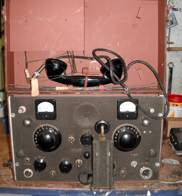 |
| With handset stowed in the accessories lid. The original handset uses cotton covered cable. The lid and and interior of the case are sprayed with red lead primer. It is not known what other pieces were supplied in the accessories lid. |
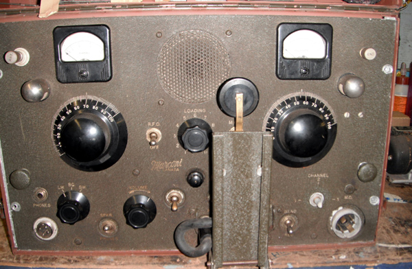 |
| A view of the front panel with the key in the stowed position.. |
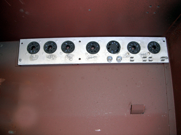 |
| This is the spares mounting bracket which is affixed to the upper right corner of the case interior. It can accommodate six spare tubes, two pilot lamps and two fuses. |
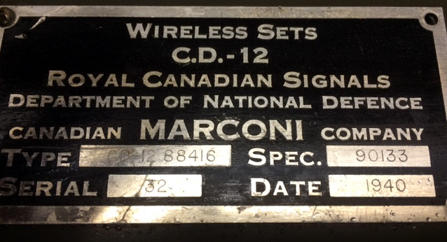 |
| Nameplate.
It reads:
Type: CD-12 88416 Spec: 90133 Serial: 32 Date: 1940 |
| All photos in this table by Moe Fretz |
 |
| CD12- top view |
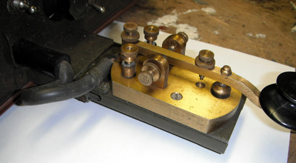 |
| The key in its unfolded position. It's made by the Signal Electric Company, of Menominee, Michigan. |
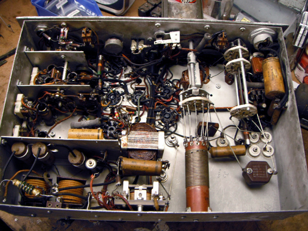 |
| CD12 - Bottom view of chassis. |
| All photos in this table by Moe Fretz |
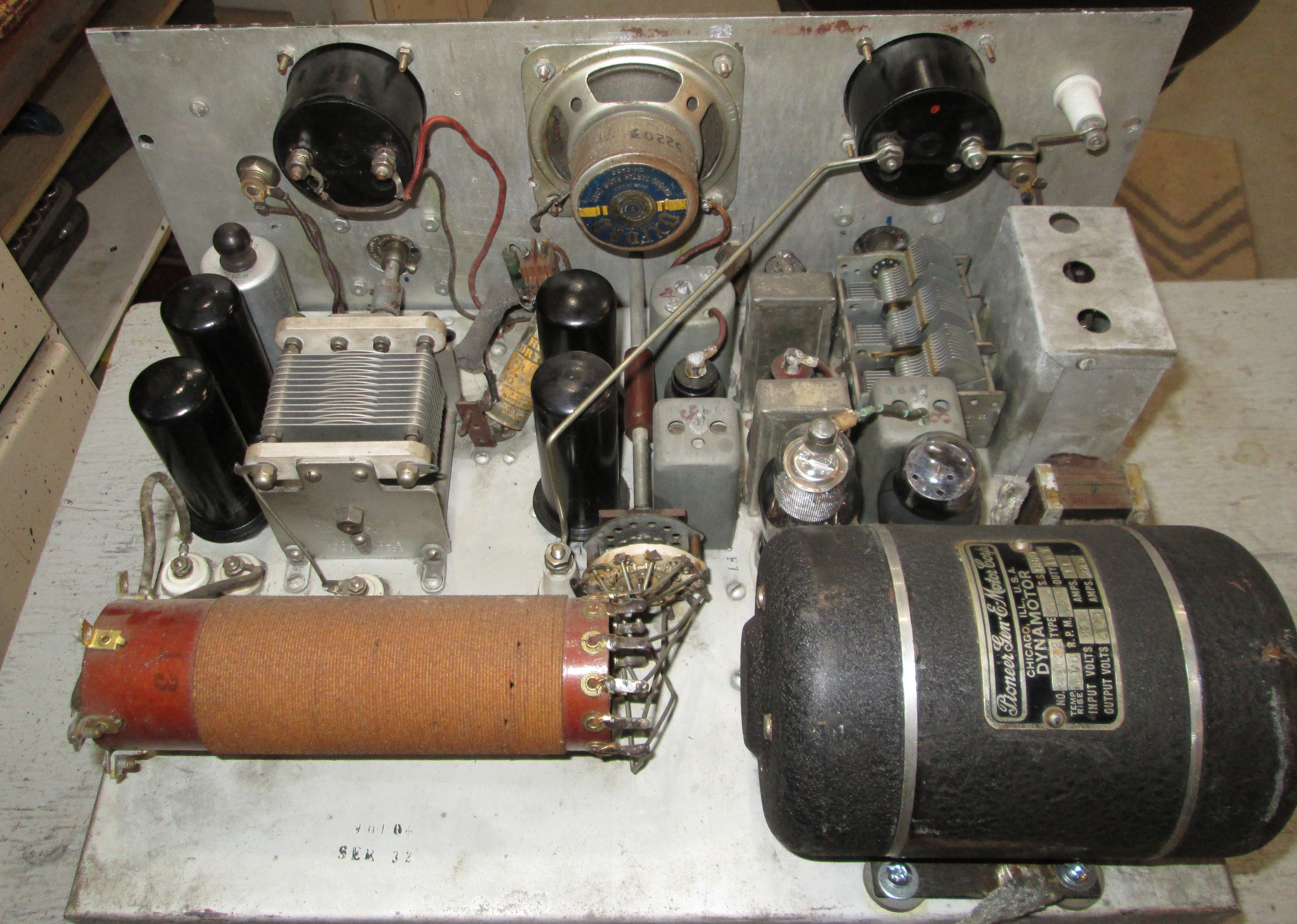 |
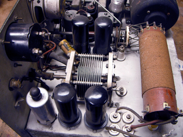
| #1 - Top view of chassis. Click on image to enlarge. (Photo by Steven Cavanaugh VE3PTA) |
| #2 - Top view of chassis.Click on image to enlarge. (Photo by Gerry O'Hara) |
FREQUENCY CONTROLUsing the Channel switch on the front panel, one of two crystal controlled frequencies could be selected . For operation under Master Oscillator control, the MO position is used. To adjust the MO to a new frequency, the operator removes the dust cover from the front panel hole opening marked MO. Behind that hole is a variable capacitor. Using a small, flat bladed screwdriver, the oscillator stage is then retuned to a different frequency then the dust cover is reinstalled. A frequency meter will be needed to set the MO to the new desired frequency.
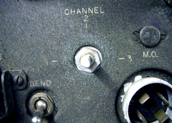 |
| The selection of either of two crystals or the Master Oscillator is done with a three position rotary switch on the front panel. In this CD12 example, the Channel knob is missing. . |
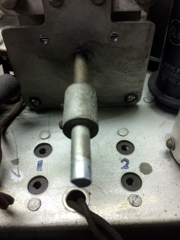 |
| These are the chassis mounted crystal receptacles. |
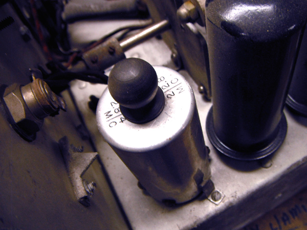 |
| The MO coil shield bears the markings of 2128 and 2814 KHz. A pointer on the back of the front panel indicates which MO frequency range is in use. These frequencies are in the range of frequencies used on radio circuits of the Canadian Army, Pacific Command during WWII. |
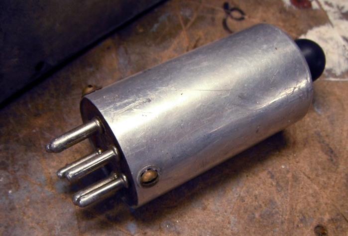 |
| Exterior view of the Master oscillator coil assembly. |
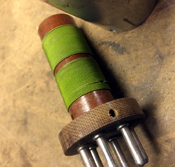 |
| Interior view of the master oscillator coil. |
| All photos in this table by Moe Fretz |
The following CD12 documentation is available for download:
| CD-12 Manual Includes tiled schematic. (Courtesy Tom Brent) |
| CD-12 Schematic only PDF, stitched version. (Courtesy Moe Frretz ) |
| CD-12 Overview Sheet |
ERRATA
The nameplate on the dynamotor made by Robbins & Myers indicates an output voltage of 350 VDC at 225 ma.
Contributors and Credits:1) Tom Brent <navyradiocom(at)gmail.com>
2) Moe Fretz <tubetester(at)gmail.com>
3) Steven.Cavanaugh {steven.cavanaugh(at)outlook.com]
Mar10/23