CGRT-1 Transmitter
SUMMARY SPECIFICATIONS
Type: High
powered transmitter; RCN stock # 5820 000060
RCN Manual reference:
BRCN 2623
Frequency range:
4 to 27 MHz
Modes: CW, MCW and
Phone
Power out : 20 kw
Mains power: 575
VAC, 3 phase 60 Hz
Circa: July
1955
Made by Canadian
Marconi
Comment, The front
of the manual indicates two Marconi contract numbers, both bearing
serial numbers. The only possible RCN use by a transmitter of this
power level would be at the RCN's transmitting sites at Newport Corners
N.S. and Matsqui B.C.
DETAILS:
1. The RCN CGRT-l
Transmitting Equipment as manufactured by the Canadian Marconi Company,
is designed for use as the main high frequency transmitter of a naval shore
station and to be used for communication with ships at sea and with other
distant shore radio stations. The equipment has a nominal power output
rating of 20 KW, and operates over the frequency range 4 to 27 MHz on Radio
Telephone, Radio Telegraph, and Radio Teletype Frequency Shift emissions.
Number; of Channels
and Types of Emission
2. The equipment
comprises two complete radio frequency channels served by a common power
supply and, if installed, a common modulator. Thus full power output is
available from both channels simultaneously, or with both channels on either
radio telegraph or frequency shift operation; with one channel on radio
telegraph and one channel on frequency shift operation, or with one channel
on radio telephone and one channel on either radio telegraph or frequency
shift operation. In some cases the modulator is not installed, so that
radio telephone operation is not possible.
Local and Remote
Control Systems
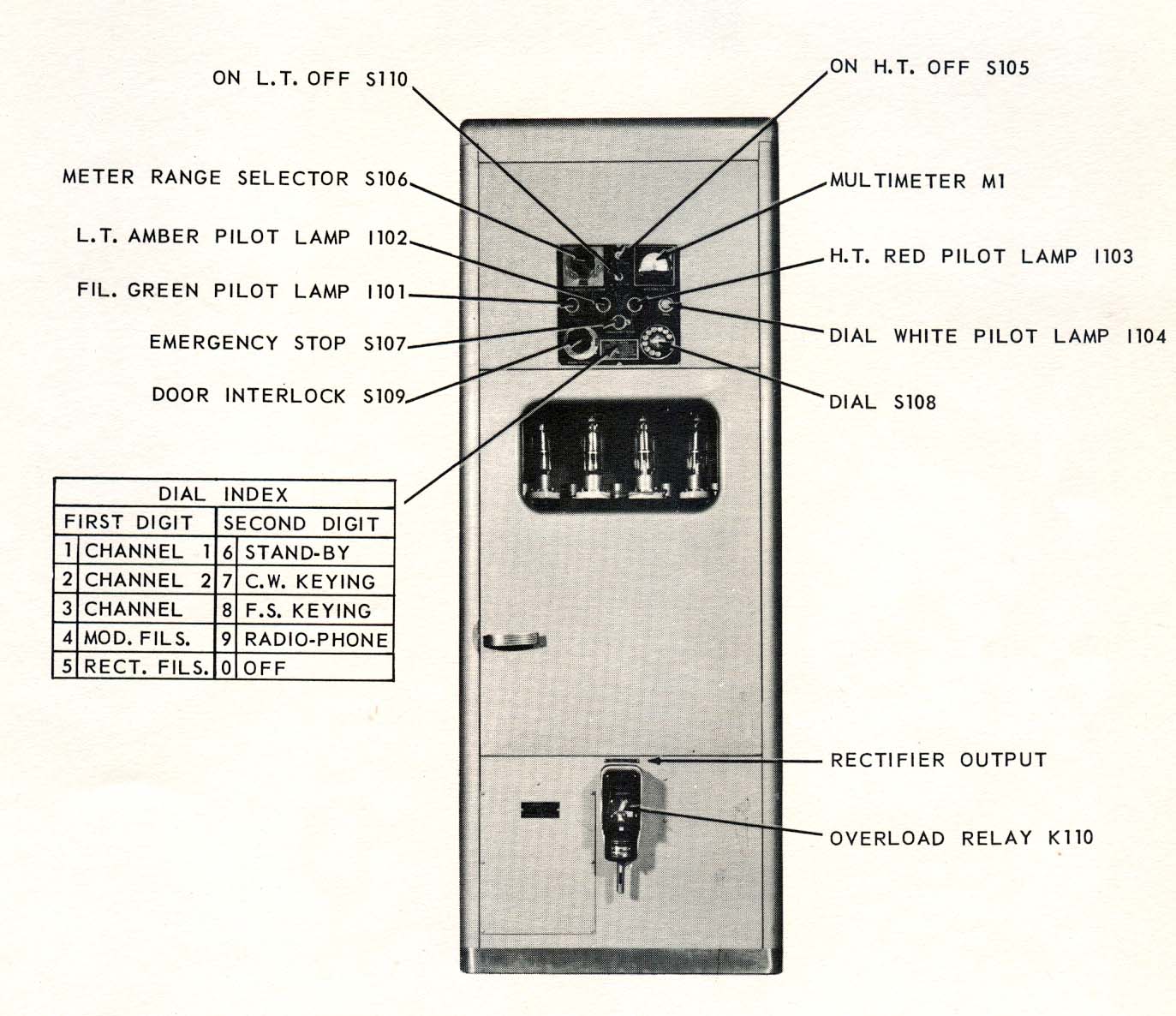
3. Operation of the
transmitter can be controlled either locally at the transmitter, or from
either, or both, of the two remote control positions. The master control
position is located at the transmitter site, and at this position it is
arbitrarily determined whether the control shall be local or remote. Control
of the following facilities is available from each of the three control
positions:
(a) On-Off Switching
(b) Standby-Operate
(c) Channel Selection
(d) Emission (ie.
- Radio Telegraphy, Radio Teletype Frequency
shift, or Radio
Telephone if a modulator has been installed).
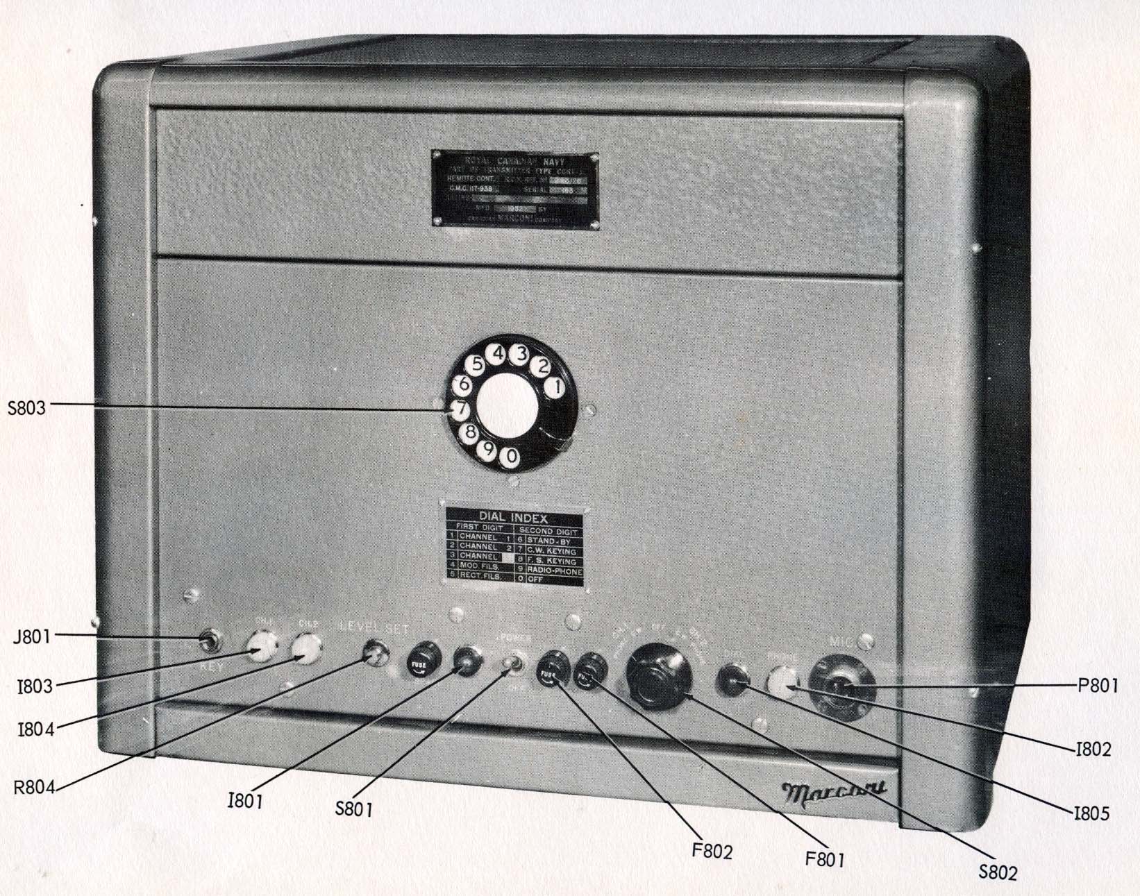
At the remote control
positions the channel and the type of emission to be used by each operator
at any time is a matter for agreement between those operators.
Indicating devices
are provided to prevent the use of conflicting facilities by the
remote operators at the same time. All control operations are initiated
by the
local and the remote
operators through the use of individual telephone-type selecting dials.
Power Supply
4. The transmitter
is designed to operate from a power supply source of 575 VAC , 3-phase,
60 Hz. The power demand is approximately 125 KVA at 95% power factor, with
full power output from both channels simultaneously, and with one channel
modulated 100%. The local and remote control units operate from a 115 V,
60 Hz power source and draw approximately 1. 5 amps each. A separate
115 VAC 60 Hz power supply capable of delivering 200 VA, is required
for the heaters of the crystal ovens.
Output Impedance
5. Both channels
are designed to work into a transmission line with nominal impedance of
600 ohms balanced to ground, with a standing wave ratio
of not more than
1. 250
Frequency Control
6. Frequency control
is by means of crystal or master oscillator, with provision for 10 crystals
per channel in the crystal oscillator. Quartz crystals type
CR18/U, or an external frequency shift keyer, of output power 1 watt
mini mum in 72 ohms, may be used. The output-to-input frequency ratio is
2 from 4 MHz to 8 MHz:, 4 from 8 MHz to 16 MHz; 8 from 16 MHz
to 27 MHz.
Design Features
7. The equipment
has been designed so that a complete frequency change on either channel,
from any frequency in the overall operating range of any other frequency
in the overall range, can be made by one operator in 5 minutes or less
provided these frequencies have been logged in advance,
Air cooling is used
for all components, including vacuum tubes and iron cored components. On
radiotelephone operation, circuits for the prevention of overmodulation
by peak-clipping, and for the elimination of background noise by squelch
action between words and sentences, can be introduced by the operation
of a switch. On telegraph operation, electronic keying is used, and
keying speeds up to 400 words per minute can be obtained. The front panel
of each main unit of the equipment carries a door interlock consisting
of an electro-mechanical device which is arranged so that it removes high
operating voltages from all exposed components, and grounds those components
before access can be gained to them. In addition, grounding rods are provided
at convenient points in each unit.
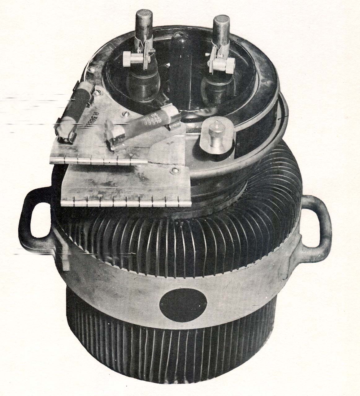
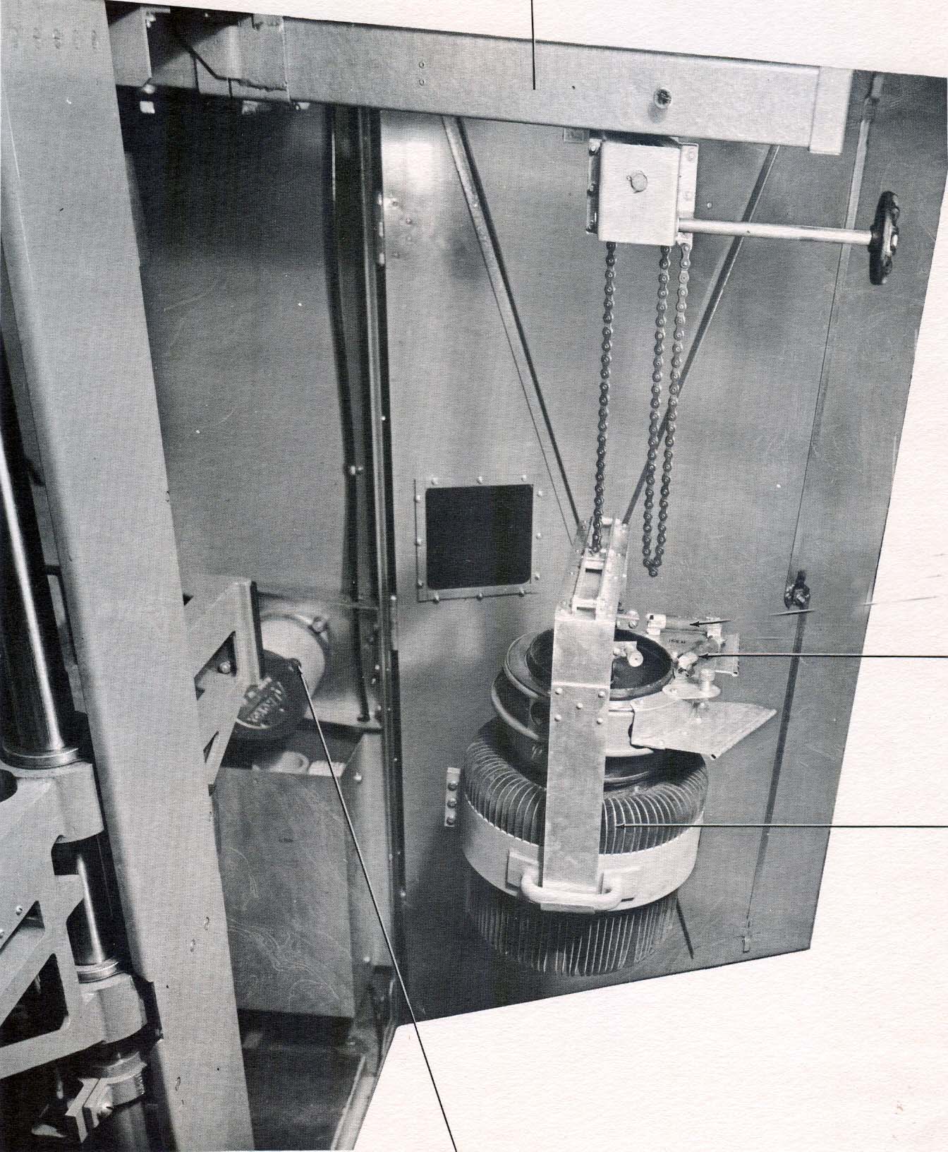
8. A typical
installation, consists of a HV rectifier, LV rectifier, modulator, two
PA units and a driver with associated transformers, ductwork,
blower and voltage
regulator, These components require a floor space of 13 x 30 ft with a
ceiling height of 11 to 12 feet , Such an arrangement permits the transmitter
to
be mounted on a
20 inch platform with manifolds underneath and with transformers, blower,
etc,., at the rear of the transmitter.
9. The weight of
the entire system is 16,200 pounds.
There are 71 rubes
in this transmitter if fitted with a modulator.
The major components
of the transmitter are:
Power Amplifier Unit
for Channel 1 #117-932
Power Amplifier
Unit for Channel 2 #117-932
Driver Unit
#117-933
Modulator Unit
#117-931
High Voltage Rectifier
#117-936
Low Voltage Rectifier
# 117-934
The manual used as
the source has a lot of missing pages so its not possible to show
a complete transmitter As a result, only selected views will be shown
in the table below .