 |
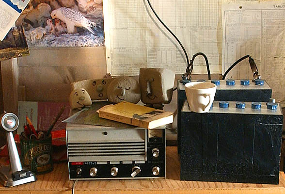
| The CH-25 in a museum mockup of a Northern Canadian radio station. (Photo by Harry Foster) |
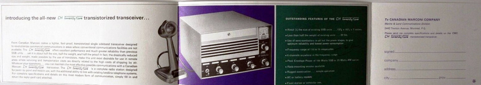
CH-25 and 26 SSB Transceiver SPECIFICATIONS
Modes: SSB (Upper/Lower), AM, CW
Frequency Range: 3 MHz to 22 MHz
Power Output: 100 watts SSB PEP; 60 watts phone
Frequency Control: Six crystal controlled positions.
Power Input: 12 VDC confirmed; possibly an AC power supply is available.
Marconi Type: 189-575
Dimensions: 11 x 7 x 13 deep
Weight: 13 kg ( 28.6 lbs)
Comment: Used in Canada's North in 1960's and 70's.
Manual: Select this link for the CH-25 and PH-17 manual.Other comments on the CH-25 are provided by Jack van Oostveen, PA3GYM, The Netherlands.
"It was a hybrid transceiver. The receiver is solid state as well as the local oscillators and balanced SSB mixers in the transmitter section. The transmitter driver and PA stages use tubes - two 6883B's with 12 volt filaments in the PA , one 6CL6 as a driver tube and a 7360 dual beam mixer tube.The HT supply is 750 volts, bias approximately - 66 volts and the transmitter LT line is 300 volts. A 9.6 VDC power supply is used for the receiver circuitry and that portion of the transmitter which is solid state. During transmit, the 12 VDC input was converted to 750 VDC by the "trill converter unit" which produced a very audible noise.
When my set was purchased, it came with one crystal for 5386.5 kHz for USB. The other five crystal positions and coil receptacles were empty. Since the set lacked a bandswitch, it was necessary to plug in the appropriate Rx/Tx coil set for the desired band of operation and made sure it matched up with the crystal frequency. When crystals were ordered for the CM-25 set they had be either 455 kHz above or below the desired operating frequency. A maximum of six different operating frequencies could be "programmed" that way.
For amateur radio operation on the 80 meter band, I altered the RX input coils, and TX coils, added a variable preselector and driver selector and a new adjustment for the PA stage. Instead of operating with crystals, I made a home brew VFO. For SSB operation (both USB and LSB) I used two crystals (453,5 kHz and) 456,5 kHz) which resulted in a 1.5 kc wide passband while still giving good audio. SSB filtering is accomplished by a Collins 455 kHz mechanical filter.
In AM mode, the passband is 6 kHz band wide. For CW operation there was a side tone oscillator running at 800 Hz. My home brew VFO covers the band between 3.600 kHz to 3.800 kHz and has a digital readout display, thuis providing the actual RX / TX frequency".
One technician made this remark about the CH-25. "My time at Bell Canada was spent in the field servicing the Marconi CH25 HF-SSB transceiver (as in Completely Hopeless Model 25) which went through endless finals when they weren't blowing out the cathode resistors. But they used Collins mechanical filters so they had some redeeming value".
|
| The CH-25 in a museum mockup of a Northern Canadian radio station. (Photo by Harry Foster) |
Two CH-25's that were on sale on E-bay had the following crystals installed: 3171, 4532, 4571,4573, 4825, 4922, 5313, 5814 and 9462 KHz .
PHOTOS
 |
| This CH-25 is owned by Jack van Oostveen, PA3GYM |
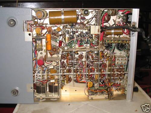
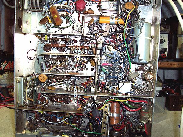 |
| Under chassis view. |
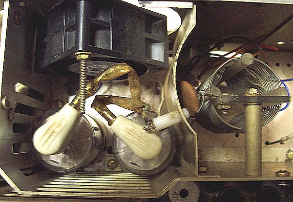 |
| R.F. compartment showing the two 6883B output tubes. |
 |
|
|
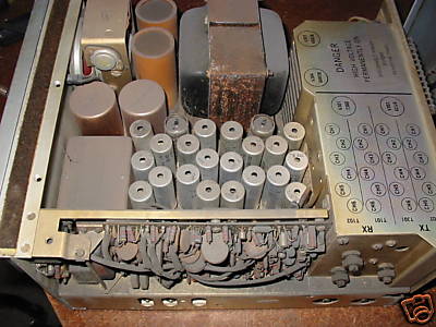
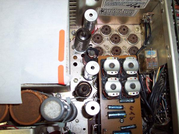 |
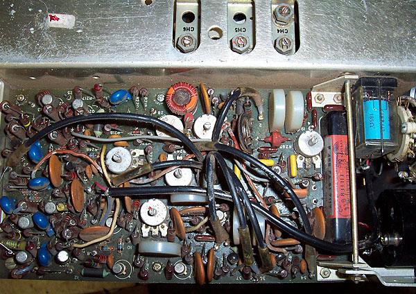
| The sockets for the crystals and coils can be seen in the top right portion of the photo. |
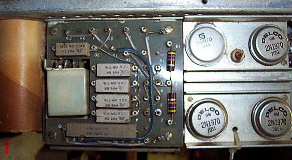 |
| The Trill Unit which converts 12 VDC to 750 VDC. This CM-25 was likely made in 1971 as attested by the date code on the power transistors. |
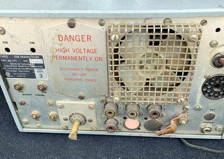 |
| CH25 rear view. |
| All photos in this table by Jack van Oostveen, PA3GYM |
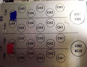 |
| Cover plate with TX and RX tube/coil channel info. |
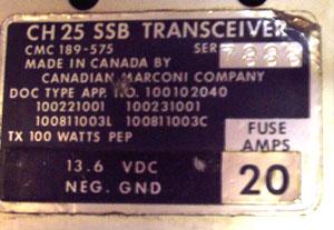 |
| CH-25 nameplate. |
| All photos in this table by Jack van Oostveen, PA3GYM |
 |
| Overall chassis view including a generous layer of dust. (E-bay photo). |
 |
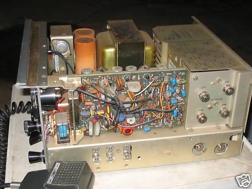 |
| Other views of a CH-25 example. |
| All photos in this table via E-bay. |
 |
 |
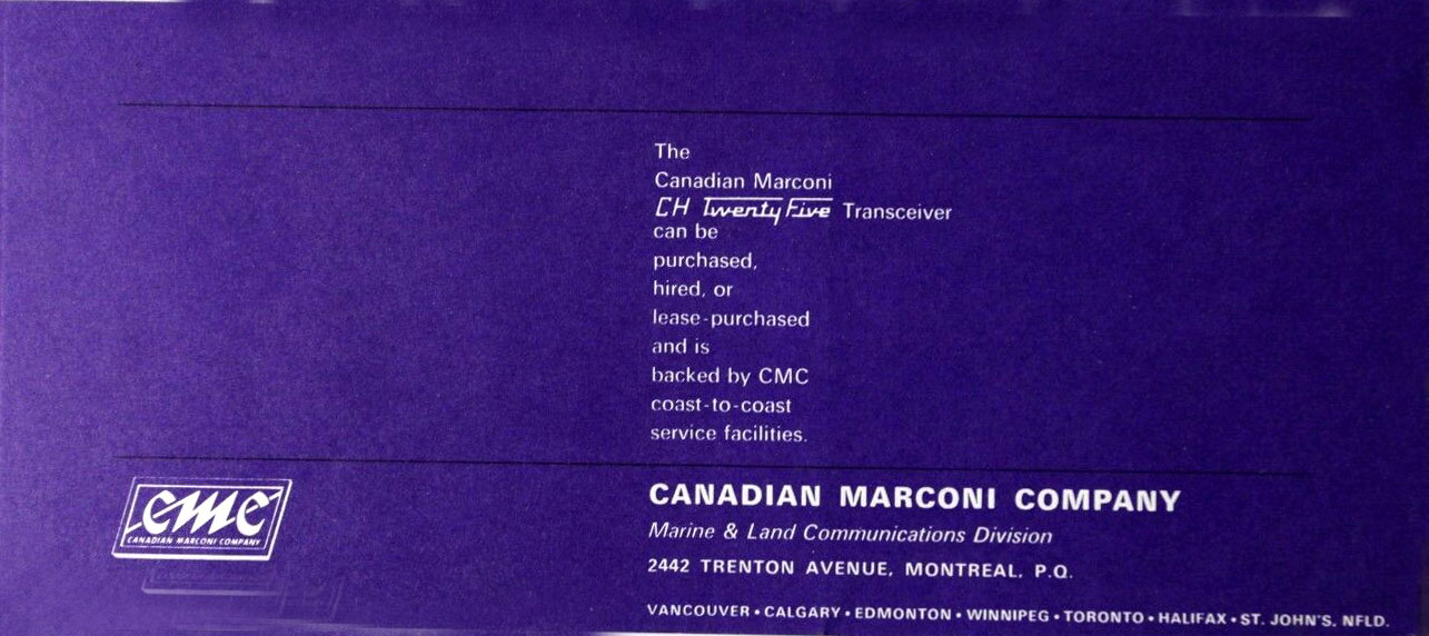 |
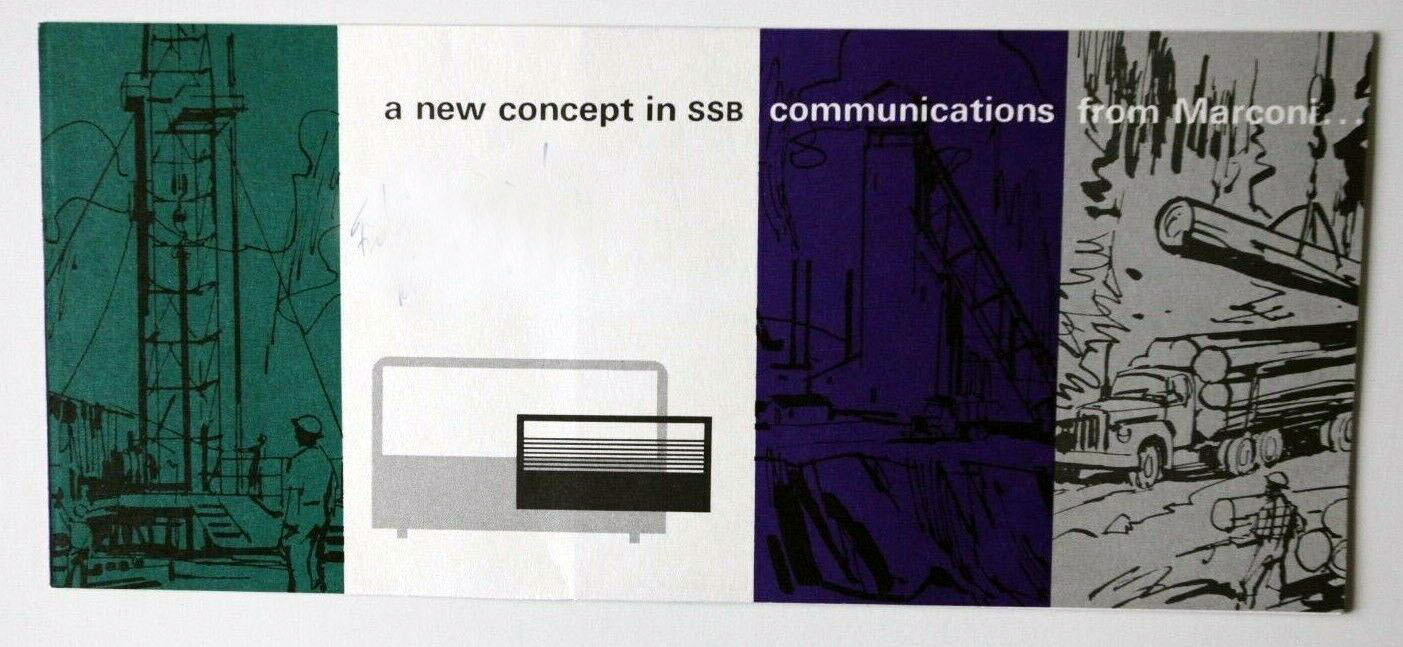
| This is a CH25 dealers brochure from 1964. Download any image in this table to enlarge. ( Images via E-bay) |
CH-26 The CH-26 was the 12 channel version of the CH-25. It used the same circuits and channel kits. The radio was wider, almost double the width but same faceplate style
BACKGROUND INFORMATION ON THE CH25
John Gilbert provides some background information on the use of the CH25 in Northern Ontario and in the NWT."From 1971-1974 several radio installations were put in place as part of the Department of Communications' Northern Pilot Project (NPP). In response to requests from participating communities, the Department arranged for the installation of HF transceivers in 18 communities in Northern Ontario in the Patricia District north of Sioux Lookout and five communities in the Keewatin District of the then NWT (now Nunavut). From 1973 the project was managed in Northern Ontario by the Wa Wa Ta Native Communications Society and in the NWT by each of the five participating communities. Technically, there were three parts to the Project.1) HF radio in all of the 23 communities. Most of these radio were Marconi CH-25 but there were a few Traeger SSB50C transceivers. .
2) "Trail" or portable HF radio using the Spilsbury and Tindall SBX-11.
3) FM radio broadcasting transmitter in two communities (Fort Severn, Ontario and Baker Lake, NWT) with the support of the CRC;
The purpose of these installations was to allow the communities to communicate among themselves, in the local languages (Inuktitut, Cree, Ojibway) and English and thus determine their communications needs for the future.HF Radio
The characteristics of the Marconi CH-25 are described above. The NPP documented additional information concerning the antennas and power requirements of the sets.
Antennas:
Two dipole antennas were provided for each site by Canadian Marconi. These were supported by three 33 ft long guyed poles, each covered with creosote at the base to prevent rotting. Installation of the antenna in the NWT was complicated by the need to thaw the permafrost in order to dig holes for the poles. The aim was to have each pole reach at least 30 feet above ground.Power
Not all communities had reliable power. In some communities a Honda E300 generator was used to power AC sets and to charge the batteries for DC sets.Trail Radio
A number of SBX-11 HF units were provided and used by the communities for communications with the communities and among themselves when travelling on the land. The Communications Research Centre assisted with the technical aspects of this part of the Project, and there was an evaluation done of the use and benefits of the equipment.
The SBX-11 provided 10w in SSB mode with 4 crystal-controlled channels in the range of 1.6 to 8 MHz. Further details are given here:
http://ei3feb.blogspot.ca/2015/01/spilsbury-and-tindall-sbx-11-portable.html
http://www.matthewkendall.com/electronics/sbx-11aThe CRC involvement is described here:
http://www.friendsofcrc.ca/Projects/TrailRadio/TrailRadio.htmlFM Radio Broadcasting
This part of the project was run separately, with the support of the CBC who advised on the selection of the 100-watt FM Transmitter (type not known). These installations required a CRTC licence and the formation of a local management team and station manager. Stations were installed at Baker Lake, NWT and Big Trout Lake, Ontario.
A formal opening of the Baker Lake Radio Station was held on February 28, 1973".
Contributors and Credits:1) http://www.civilization.ca/hist/phase2/mod11e.html
2) Jack van Oostveen, PA3GYM <jaap.oostveen(at)hccnet.nl>
3) Donald LeFevre KD5RCG <Donaldb946(at)aol.com>
4) http://mailman.listserve.com/archives/html/collins/2006-07/msg00146.html
5) Walter IsaacsonVA7ANI [wi1940@telus.net]
6) John Gilbert <jgilbert(a)ca.inter.net>
Dec 1/20