 |
|
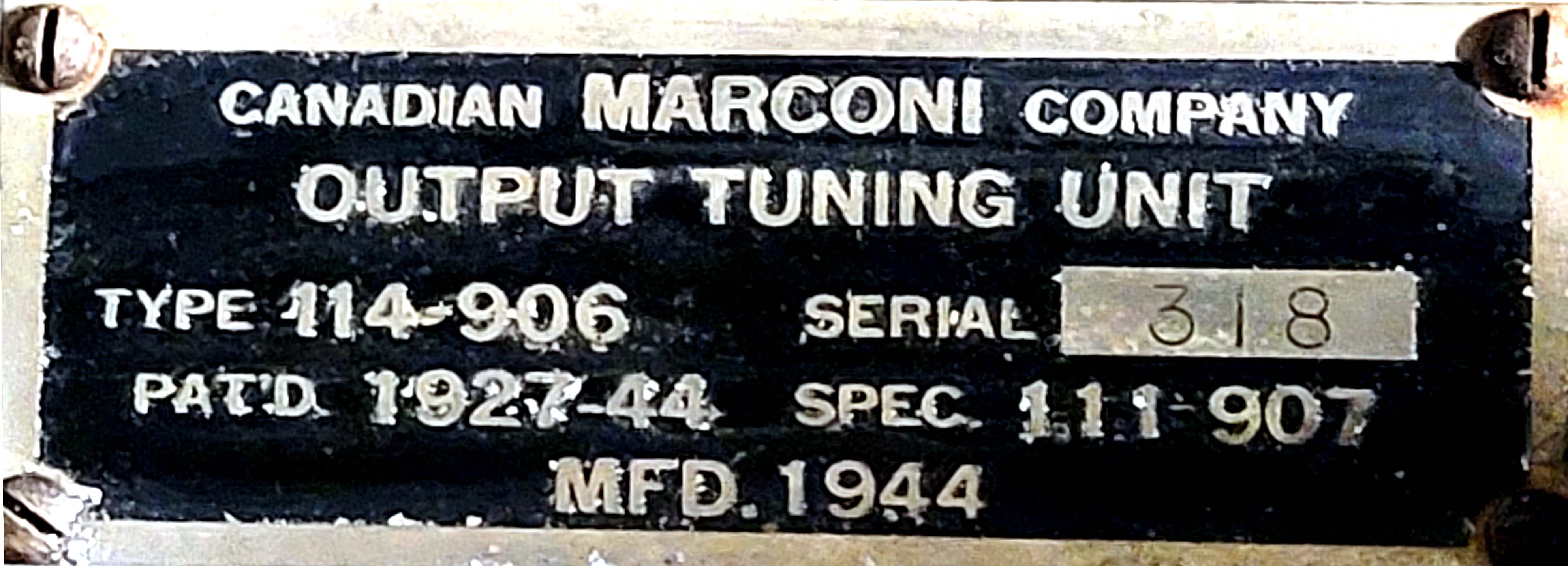
| Nameplate affixed to the antenna tuner chassis. (Photo by'Meir Ben-Dror WF2U) | |
 |
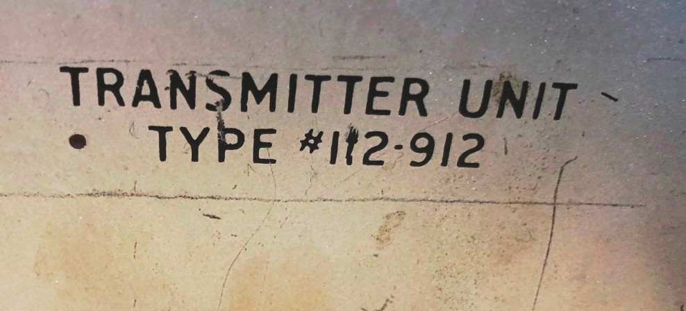 |
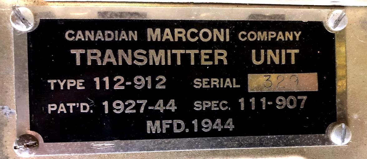
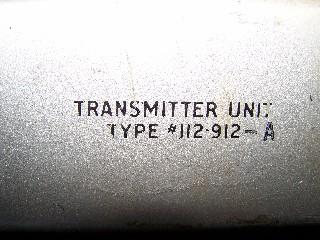
| Nameplate affixed to transmitter chassis (Photo by Gerry O'Hara) | Silk screen transmitter chassis markings, 5 |
CM11and CM11A Transmitter-Receiver GENERAL
First built in 1942, the CM11 was a transmitter/receiver that was capable of operation in the 375 KHz to 13.5 MHz range. There were two distinct bands of operation: 375 to 515 KHz on low frequency and 1.5 to 13.5 MHz on high frequency. In the high frequency band, the CM11 could be used with crystal or master oscillator frequency control. For low band operation, only the master oscillator could be used. The RCN labelled CM11 crystals with two additional frequencies besides the fundamental - the second harmonic and the third harmonic. On HF, the transmitter could be tuned to operate on any of the three frequencies. Modes and power levels were: CW - 100 watts; MCW - 70 watts; AM - 30 watts. The Signal Electric R63 was the key provided with the CM11 - RCN pattern number 3M/103.
CM11 is the designator for a radio system comprised of a CSR5 or CSR5A receiver , a type 112-912 transmitter , a type 114-906 output tuner and the ZM-11 power supply. The TM11 is the system designator for a type 112-912 transmitter with a 114-906 output tuning unit and a ZM11 power supply less the CSR5receiver . A blank plate is installed in lieu of a CSR5 receiver. CM11's in service with the RCN were modified to operate with a "Man Aloft" key. This safety feature prevents the final RF stage in the transmitter from being energized in case f someone has to climb the mast to work on the antenna. The lock was fitted to the cabinet of the CM-11 at the left side near the top.
MAJOR COMPONENT IDENTIFICATION
|
|
| Nameplate affixed to the antenna tuner chassis. (Photo by'Meir Ben-Dror WF2U) | |
|
|
| Nameplate affixed to transmitter chassis (Photo by Gerry O'Hara) | Silk screen transmitter chassis markings, 5 |
 |
| The
CM11 nameplate is found on the front of the CM11 cabinet, at the bottom.
The other tags indicate that CM11 S/N161 was refurbished on February 14, 1962 to the revision level shown on the CANMODPLATE.. Click on image to enlarge. (Photo by Gerry O'Hara) |
The following table has been posted to record the serial numbers of various CM11 subassemblies, It is hoped that if enough serial numbers are captured, it will provide a rough picture of CM11 production.
| IITEM a | TYPE | SERIAL NUMBER(S) | RCN Patt. No. |
| Output Tuning Unit | 114-906 | 310, 319 | 3AU/19 |
| Transmitter Unit | 112-912 | 162, 329, 321 | 3AU/18 |
| Receiver - CSR-5A * | 110-480AZ | 301. 399 | |
| Receiver - CSR-5 | 110-480Z | 320. | 3AU/17 |
| CM11 (system) | 110-981 | 161, 219, 225, 298 ,307 | |
| CM11A (system) | 110-981A | ||
| ZM11 (Tx) High voltage supply | 102-900 | ||
| ZM11 (Tx) Low voltage supply | 102-902 | ||
| ZM11 - Receiver supply | 102-903A | ||
| ZM11 - Overall | ? | ||
| ZM11A - Overall | 110-982A |
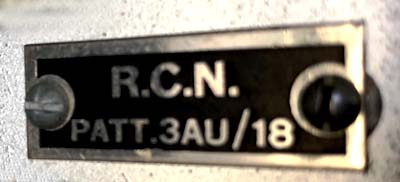 |
| This tag was found on a CM11 transmitter chassis which was missing its nameplate. It is an RCN pattern number for the transmitter and is not listed anywhere in the parts section of the CM11 manual, Normally, all CM11 parts are associated with an RCN pattern number which was the RCN's internal inventory system. This is the pattern number for the Antenna Tuning Unit. ( Photo by Gerry O'Hara) |
KNOWN LOCATIONS OF CM11 TRANSMITTERS (as of May 2021)
| QUANTITY | NAME/LOCATION | STATUS |
| 3 | HMCS Haida , Hamilton, Ontario | One working unit. One unknown; one inoperative |
| 2 | Maritime Museum of the Atlantic, Halifax N.S. | One
working unit; one parts unit.
Received from the former Radio Museum of Quebec |
| 1 | HMCS Sackville, Halifax N.S. | Unit is complete but not operational. |
| 1 | RCSCC Iron Duke, Burlington Ontario. | Missing ZM 11 power supply. |
| 3 | Saltspring Island. B.C.. | One is working; TBA for the other two. |
| 1 | SPARC Museum , Vancouver, B.C. | Status unknown at this time. |
Inter-connection between the transmitter, receiver and antenna tuner was provided by snatch plugs and electrical bus. These connectors operate on the same principle as knife switches. Each of the three slide out assemblies in the CM11 are equipped with female snatch plugs. When slid into place, the antenna tuner, transmitter and receiver interconnect through a wiring bus that is fitted with male snatch plugs. The CM11 antenna tuner was a very versatile device, since it could match antennas that were 5 to 750 ohms resistive and supported operation in the range of 375 KHz to 13.8 MHz.Keith Kennedy ex-C2NET(s) of Surrey BC notes that "the CM11 was notorious for generating harmonics and spurious emissions and HMC Ships would routinely receive harmful interference reports from the Department of Transport monitoring station located at Wetawaskin Alberta. We had little in the way of test equipment and certainly nothing as fancy as a spectrum analyzer so we just followed the CM11 tuning instructions and filed the reports away. The CM11 was also known for its chirpy CW signal when controlled by the master oscillator but it behaved properly under crystal control. CM11's also had a bad habit becoming detuned as the ship rolled. It was the result of changing capacitance between the antenna and the surface of the sea".
Eventually, the CM11 was superseded by the AN/URC32 transceiver in the Royal Canadian Navy.
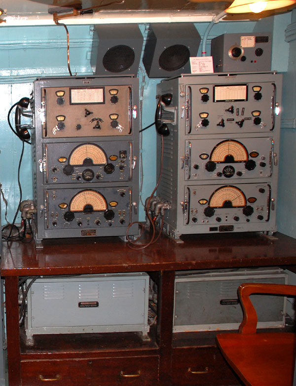 |
| This dual CM-11
installation is found in Radio 2 aboard the destroyer HMCS HAIDA. The left
most unit is connected to bare copper transmission line with a quick disconnect
switch mounted on the deckhead. The rightmost CM-11 has a coaxial connector
fitted atop the cabinet and feeds RG-18 coax. Both of the bulkhead mounted
CM-11 speakers are near replicas constructed by Jerry Proc. Below each
CM-11 is the ZM-11 power supply. (Photo by Jerry Proc)
In the 1960's the RCN experimented with tuning adjustments of the CM11. Atop the rightmost CM11 is the experimental E-886 antenna tuner. A replica of this tuner was constructed by Jerry Proc from microfiche supplied by the Canadian Navy. There are no records around to indicate what it is supposed to do . |
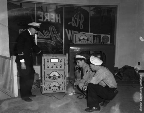 |
| This CM11 appears to be staged in an auto dealership store front in Mission, B.C. The reason for setting up this station in the car dealership was to assist with a major disaster, namely, the Fraser Valley flood of June 1948. The RCN was called out to help and so was the Canadian Army. The sign says "Its HERE THE NEW Austin". (Mission BC Community Archives) |
SPECIFICATIONS
Frequency Range: LF - 375 to 515 KHz
HF - 1.5 to 13.5 MHz
Modes: CW/MCW/AM . On MCW the note is fixed at 1,000 Hz.
Frequency Control: Crystal or Master oscillator.
RF Power: 100 watts on CW; 70 watts on MCW and 30 watts on voice.
Antenna Impedance: Will match antennas that are 5 to 15 ohms resistive on LF or
15 to 750 ohms resistive on HF.Primary Power: 115 VAC @ 5.4 amps, 60 Hz or 24 VDC @45 amps.
Weight: 478 pounds including power supply.
Colours: The CM11 is known to have been painted in:
a) a tan , mat finish
b) light, smooth gray enamel.
c) Medium dark, blue-gray crackle finish.
d) light green
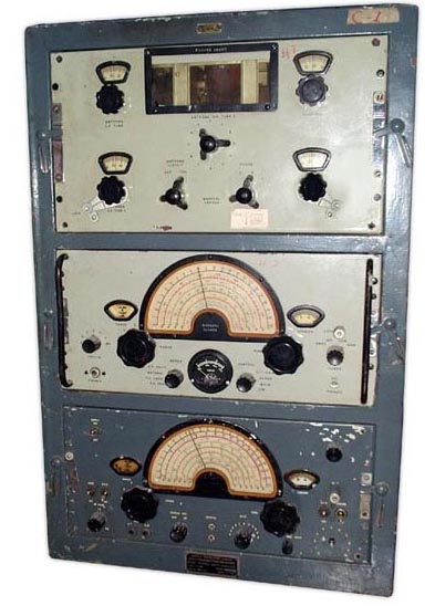 |
| This CM11, held in the collection of Denis Chouinard, shows the light green colour of the 112-912 transmitter and antenna tuner sub-assemblies. (Photo by Denis Chouniard) |
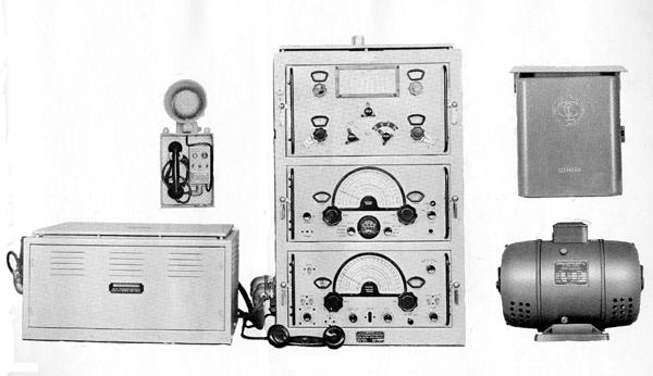 |
| CM-11 system showing major components. (L-R) Power supply, remote control box, handset, CM11, starter for motor alternator and finally the motor-alternator. (Image courtesy Canadian Marconi) |
 |
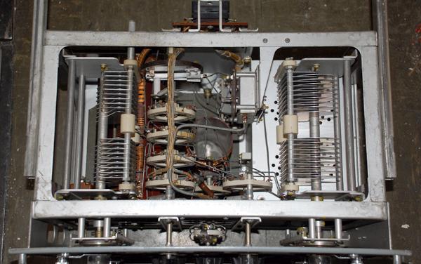
| 112-912 transmitter chassis - top view. Click on image to enlarge. (Photo by Gerry O'Hara) |
 |
| 112-912 - Closeup of the meter and major controls. (Photo by Gerry O'Hara) |
 |
| 112-912 transmitter chassis - bottom view. Someone has changed several of the caps and added some extra disc ceramic bypass caps.Click on image to enlarge. (Photo by Gerry O'Hara.) |
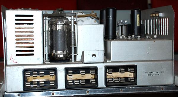 |
| 112-912 rear view. (Photo by Jerry Proc) |
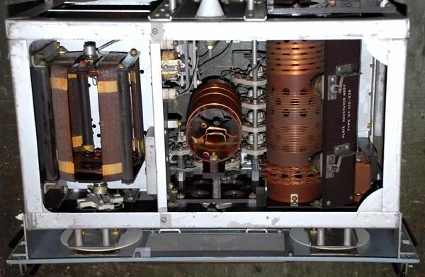 |
| CM-11 antenna tuner - top view. (Photo by Jerry Proc) |
 |
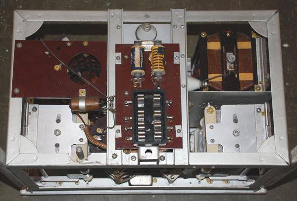
| CM-11 tuner - bottom view. (Photo by Jerry Proc) |
 |
| CM-11 tuner - rear view. (Photo by Jerry Proc) |
 |
| Antenna tuner. Front panel markings. Click on image to enlarge. (Photo by Gerry O'Hara) |
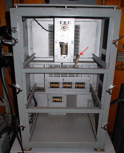 |
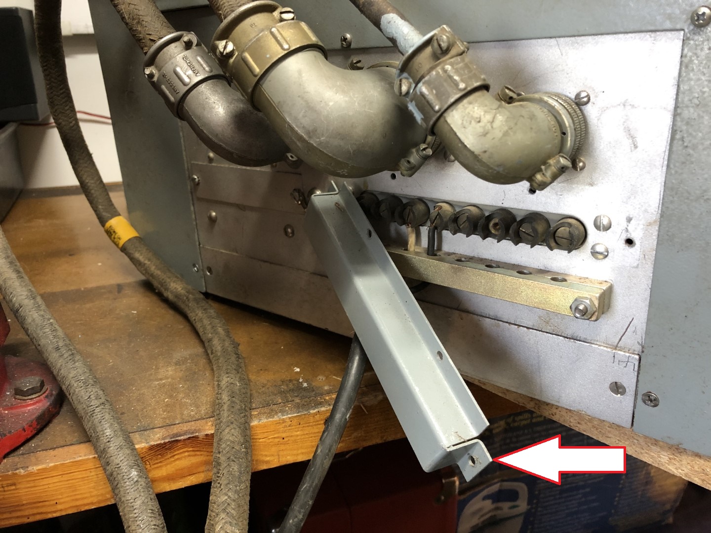
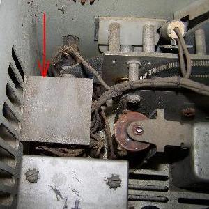
| CM11 cabinet with all units removed. The silver plated bar, indicated by the arrow, interconnects the anode of the 813 RF output tube to the input of the antenna tuner. (Photo by Jerry Proc) |
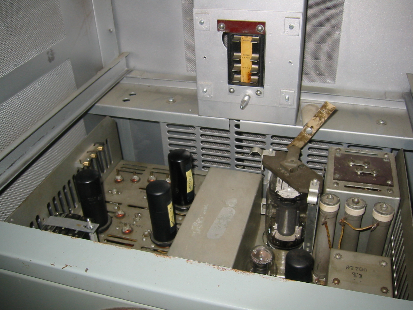 |
| This is the interior view with just the antenna tuner removed. (Photo by Jerry Proc) |
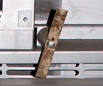 |
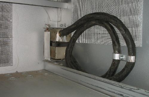
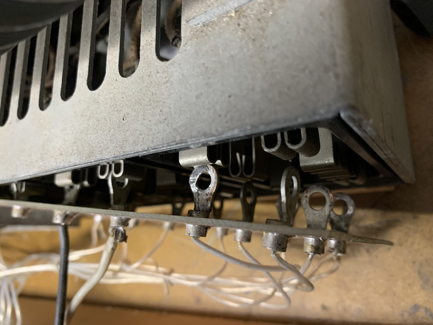
| Detailed view of TM-11 to antenna tuner interconnect strap. The fitting atop the 813 tube connects to one side of the strap, A contact on the tuner mates with the other half of the strap thus interconnecting the tuner to the transmitter. |
RECEIVER
The CSR5 receiver used in the CM11 is not included in this web document. Please refer to the CSR5 document in the Equipment listing section of this web page.
The ZM-11 power supply consists of three separate assemblies. From left to right:1) Transmitter low voltage power supply. #102-902
2) Transmitter high voltage power supply. #102-900
3) Receiver power supply. #102-903The ZM-11 power supply can operate on 120 VAC or 24 VDC power sources. A 20 second time delay circuit prevents power from being applied to the transmitter in order to protect the mercury vapour rectifiers. There was an emergency mode which decreased the time delay to 4 seconds but at the expense of shorter mercury rectifier life.
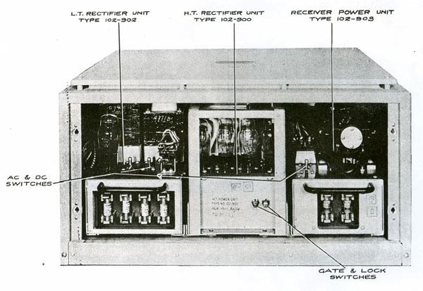 |
| Front view of the ZM-11 power supply showing the three sections. Left unit is the low voltage supply for transmitter. Middle unit is the high voltage supply for the transmitter. At the right is the receiver power supply. That dynamotor is only used when the CM11 is connected to a battery source. It is only capable of powering the receiver. Otherwise, the receiver runs from a 24 volt DC source. (Image courtesy Canadian Marconi) |
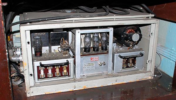 |
| ZM-11 power supply - front view. The gate safety interlock is fitted in the middle power supply. It energizes the transmitter when the cover is in place. When removed, it is necessary to engage the override switch adjacent to the gate switch if power is desired. (Photo by Jerry Proc) |
 |
| ZM-11 power supply. Top view of all three units. Click on image to enlarge. ( Photo by Gerry O'Hara) |
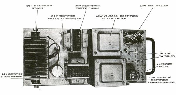 |
| ZM11 - top view of the low voltage supply for the transmitter unit.. (Image courtesy Canadian Marconi) |
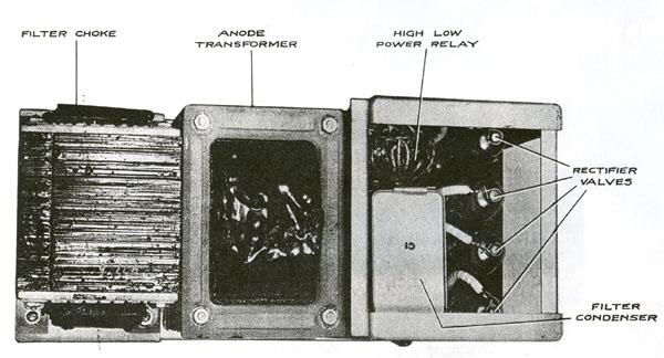 |
| ZM11 - top view of the high voltage supply for the transmitter unit. . (Image courtesy Canadian Marconi) |
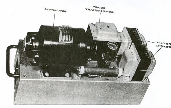 |
| ZM11 - top view of CSR5 power supply. Note the rotary converter for operation on 24 DC power systems. (Image courtesy Canadian Marconi) |
 |
| This is the cover for the terminal strip in the vicinity of the power connectors. (Photo by Gerry O'Hara) |
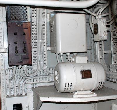 |
| This is the #122-103 dynamotor for a CM11. It converts 24 VDC to 115 V AC 60 Hz. Behind it is the starter unit #122-147. The knife switch to the left is the battery charging panel . In one position the battery is connected to the charger. In the other position, the battery is connected to the dynamotor input. (Photo by Jerry Proc) |
REMOTE CONTROL
The CM11 could be operated in radiotelephone mode by the SM11 remote control unit. An example is shown below.
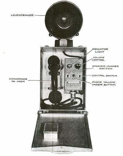 |
| This SM11 remote control unit ( #110-827) could be used with the CM-11 up to 100 feet away but only on radiotelephone. (Image courtesy Canadian Marconi) |
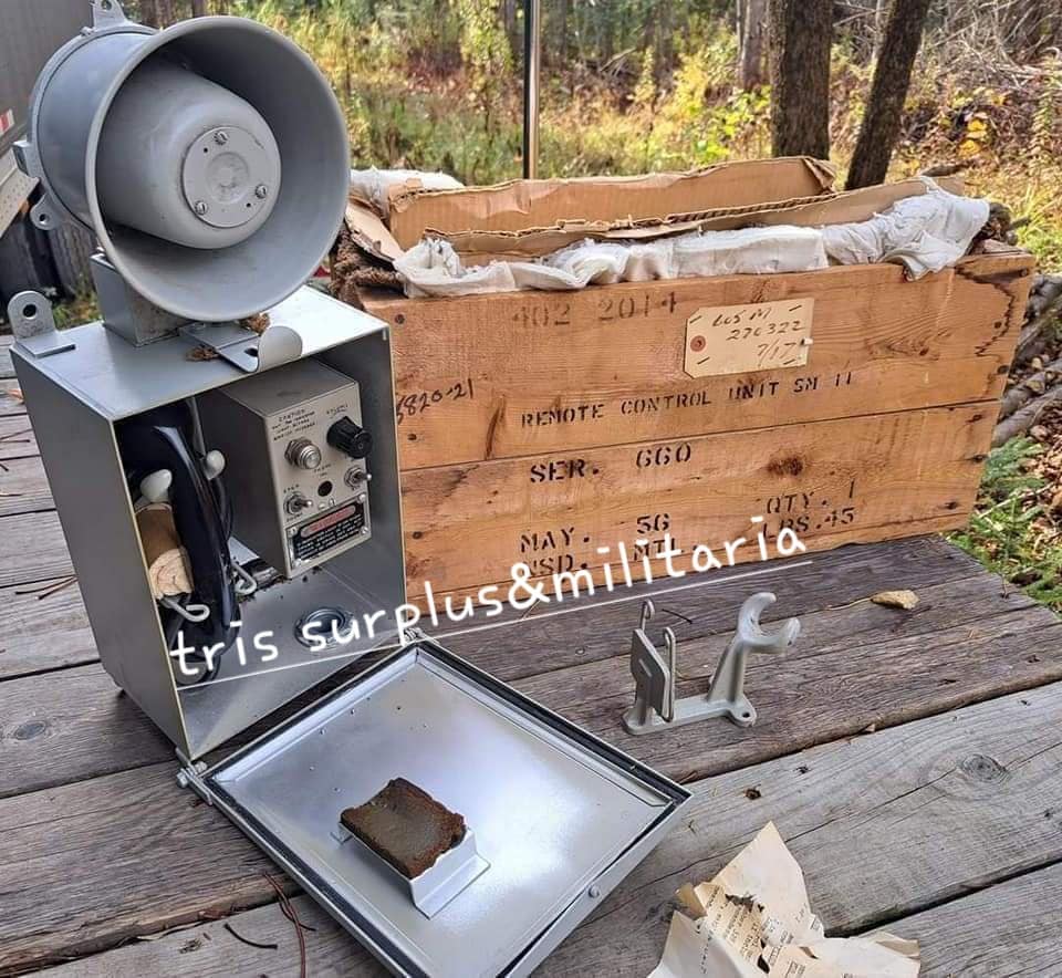 |
| This is how an SM11 (S/N 660) looked like in mint condition.. Note the1956 markings on the original shipping box. It also came with a spare handset clip. Click on image to enlarge. (Via ttris surplus&militaria) |
SPEAKER
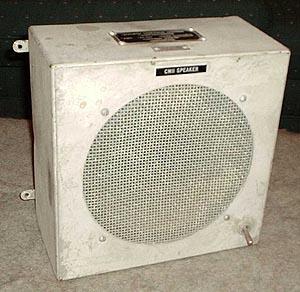 |
| The official CM-11 speaker. (Photo source unknown) |
OTHER DETAILS
|
|
|
 |
 |
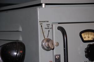
| In RCN shipborne applications, the CM-11 needed a "Man Aloft" key. If a radio operator had to climb the mast to work on the antenna, he could disable the transmitter with a key and take it with him. In the left photo, the key has been installed in the frame. At the right, the key is fitted in the front panel of the CM-11. (Photos by Jerry Proc) | |
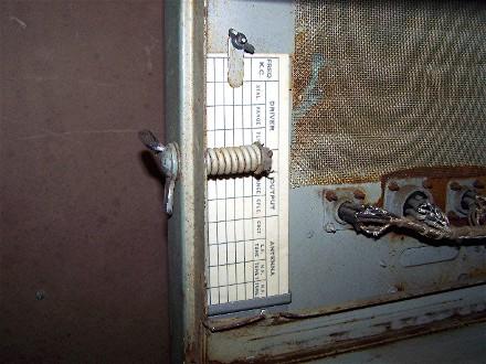 |
| The lower left area of the CM-11 frame was reserved for a blank antenna tuning chart. Not all CM11 cabinets were fitted with the spare chart feature. (Photo by Meir Ben-Dror WF2U) |
TEST CABLES
The test cable could be used to troubleshoot either the CSR-5A receiver ofr the C-11 transmitter chassis. When used with the transmitter , one end of the cable plugs into the connector marked "TESTPLUG ONLY" . This lmarking is not in evidence on some CM11 cabinets.
 |
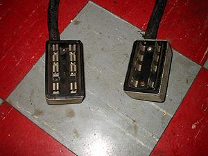
| The lower right area of the CM-11 frame was reserved for the storage of the test cable. (Photo by Jim Brewer) |
 |
 |
 |
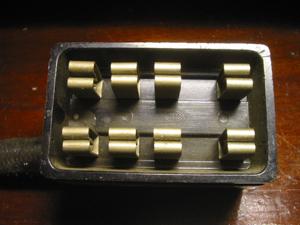 |
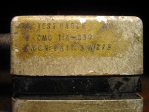
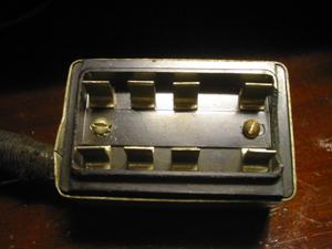
| Marconi test cable #114-830, RCN Patt No. 3?/273 (All photos in this block by Jim Brewer) | |
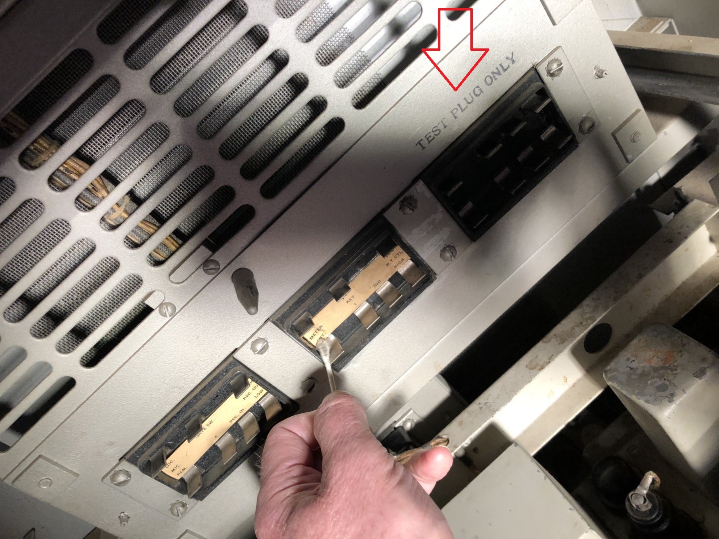 |
| The snatch connector panel at the back of the CM11 cabinet has been stamped "TEST PLUG ONLY" thus indicating the connection for one end of the test cable. The other end plugs into the corresponding snatch plug at the back of the transmitter chassis . CM11 cabinets may or may not bear this particular marking, The test cable provides 400 VDC and filament power to the transmitter chassis but no B+ to the output stage. (Photo by Gerry O'Hara) |
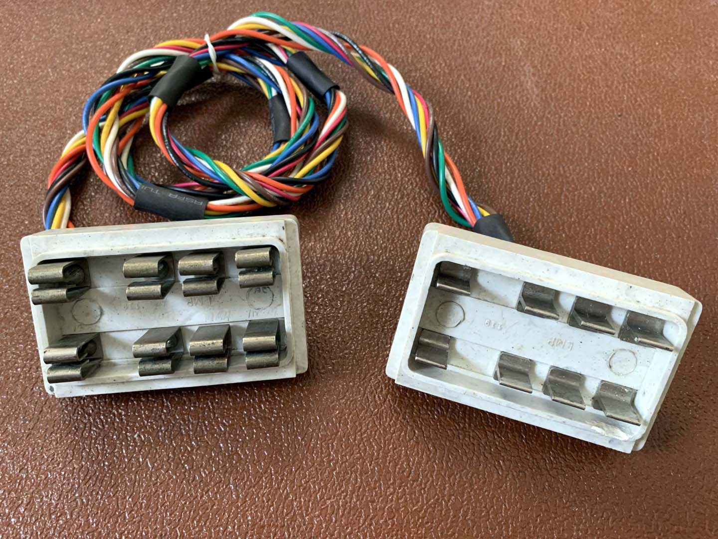 |
| Above and below: One way to fabricate a missing test cable is to recycle the snatch plugs from a junker CM11. This example was built and photographed by Gerry O'Hara. |
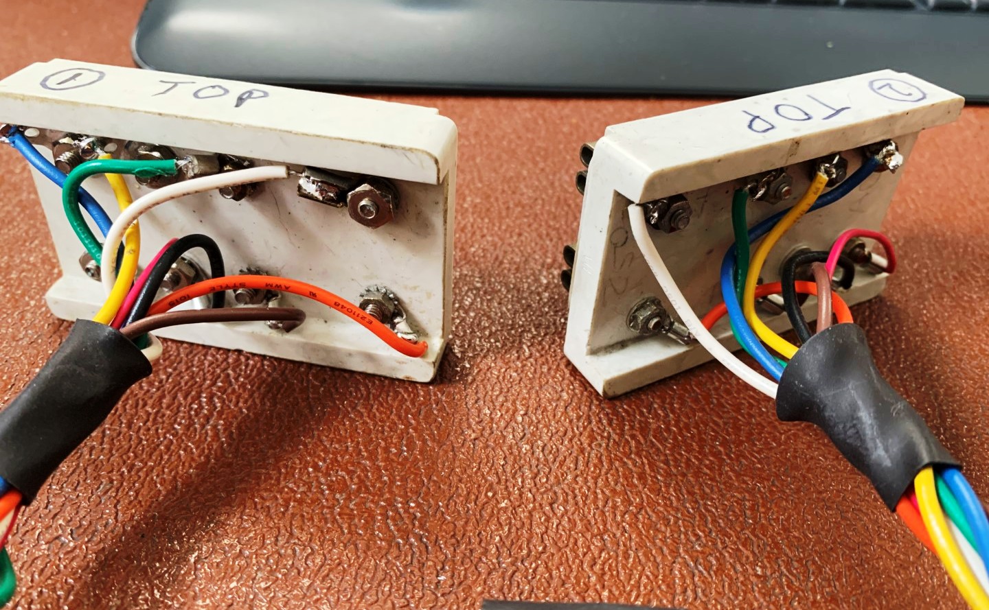 |
| Rear view of test cable connections. |
 |
| Transmitter troubleshooting mode showing the test cable in place. Click on image to enlarge. The transmitter chassis has been pulled out to its furthest point of travel. (Photo by Gerry O'Hara) |
 |
| Receiver troubleshooting mode showing the test cable in place. To troubleshoot the receiver, connect the test cable to the snatch plug at the back of the receiver chassis and the other end to the mating snatch plug inside the cabinet. Click on image to enlarge. (Photo by Gerry O'Hara) |
| This drawing shows the receiver and transmitter test modes. |
 |
 |
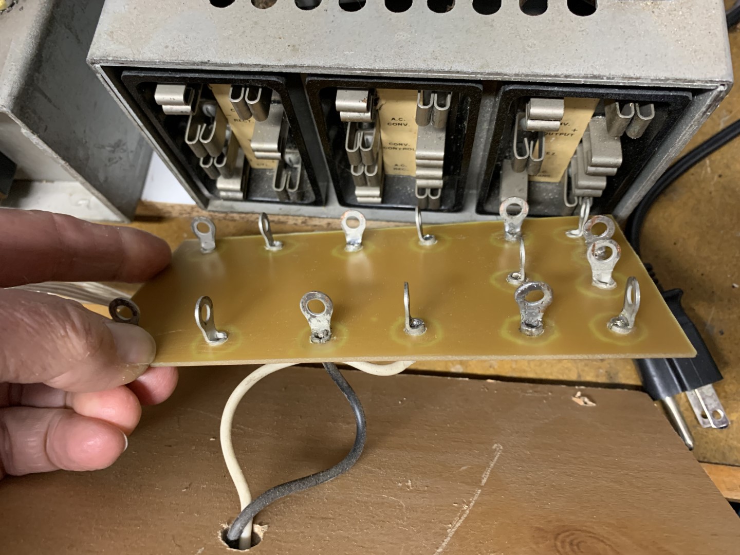
| When
a junker CM11 is not available, there is an alternate way to make a test
cable. It involves using a copper clad phenolic circuit board and eyelet-
type soldering lugs, To make such a test cable:
1) Cut the phenolic board to the same dimension as the snatch plug, perhaps a touch bigger . Holes must be drilled in the phenolic board to match the pin centers on the chassis snatch plug. 2) Around each hole, it is necessary to create am "island" of copper which is isolated from the rest of the board. 3) Noting the correct orientation, an eyelet type soldering lug is inserted in each hole and soldered. Repeat the same for the other end of the cable, 4) Then, solder all 8 wires to the lugs. 5) When ready to use the cable, gently insert the phenolic board into the correct snatch plug on the transmitter unit and the test connector mounted identified at the back of the CM11 cabinet, (Photos by Gerry O'Hara) |
|
To avoid electrical shock when using a home brew test cable, make sure that the transmitter's 400 VDC supply line in the cabinet snatch connector doesnt have any residual voltage on it. If it does, discharge it first using a low value bleeder resistor. Plug the test cable into the transmitter unit first, then the other end The same precaution should be applied to the 250 VDC B+source when using the test cable with the CSR5 receiver, |
| RF OUTPUT CONNECTIONS | |
 |
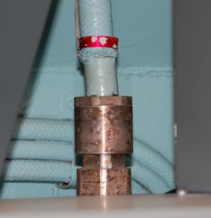 |
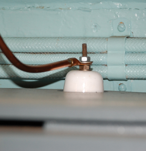
| RF output connection to bare wire transmission line using a porcelain feed through. This may not be an original insulator. | This RG-18 coax fitting has been retrofitted by the RCN. The female RG18 connector can be replaced with a SO-239 but one needs to first fabricate an adapter plate, |
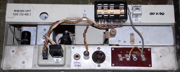 |
| Rear view of the bracket and connector assembly which adapts the CSR-5 receiver to the CM11 cabinet. Just by removing the bracket, the CSR-5 can be converted into a standalone cabinet configuration. The receiver assembly is marked 110-480Z. (Photo by Jerry Proc) |
CRYSTALS
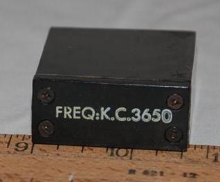 |
| The CM-11 used the standard Marconi crystal of the day. (Photo by Jerry Proc) |
 |
 |
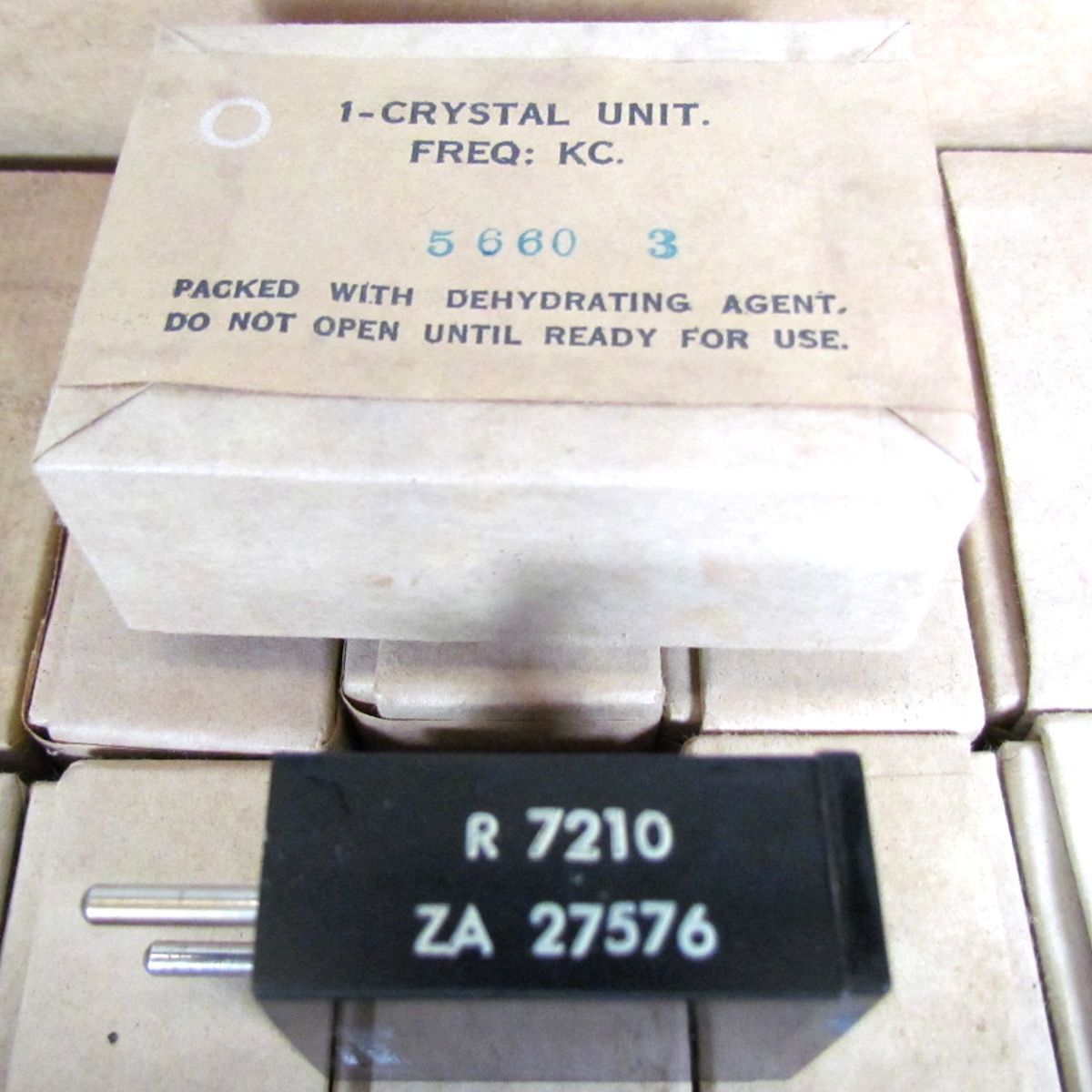 |
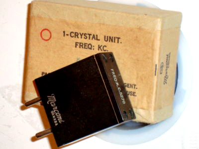
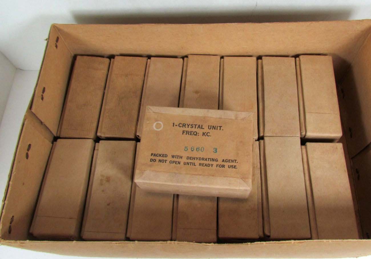
| CM11 crystals in their original factory packaging. These are known as type BY crystals. The same crystal type is used in the CSR5 receiver. The following standard RCN crystal frequencies were available for the CM11 transmitter. (Photos via E-bay) |
CM11 vs CM11A DIFFERENCES
Meir Ben Dror, W2FU has identified at least four differences in the table below.
 |
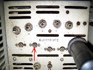 |
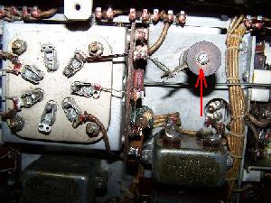
| Relay shield cover added. | An additional trimming capacitor was added in Buffer No. 2 section. |
 |
 |
| Resistor mounted vertically next to the 813 socket. | Type number suffixed with 'A' designator |
| All photos in this table by Meir Ben-Dror, WF2U | |
Another difference between a CM11 and a CM11A - the circuitry in the 112-912 transmitter unit has been modified. Tjhis affects the 1st buffer stage plate and screen circuits.
DOCUMENTATION
CM-11The CM11 manual (Canadian Marconi's version) is available for downloading although it does not include the oversize schematics depicted in Figures 19, 20 and 21. The blank antenna tuning chart is courtesy Meir Ben-Dror WF2U.
| CM11 Manual - Sections 1 to 6 |
| CM11 Manual - Sections 7 and 8 |
| Antenna Tuning Chart Blank |
| Schematics - See CM11A section |
CM11-AThis documentation has scanned from BRCN 2769 which is the RCN version of the Canadian Marconi CM11 manual. Because some of the Figure drawings in Section 8 are larger that the bed of a normal scanner, they have been scanned separately and some have been split into left and right sections in the interest of printing convenience. After printing, these documents can be taped together and trimmed to reconstitute the original information.
| CM11A Instruction Book BRCN 2769 - Sections 1 to 7 |
| CM11A Instruction Book BRCN 2769 - Section 8 (less oversize dwgs) |
| OVERSIZE FIGURES: |
| Tx- Component Identifier - Figure 3 Chassis Top View |
| Tx- Component Identifier - Figure 4 Chassis Bottom View (Left) |
| Tx - Component Identifier - Figure 4 Chassis Bottom View (Right) |
| Tx - Schematic - Figure 22 Left |
| Tx- Schematic - Figure 22 Right |
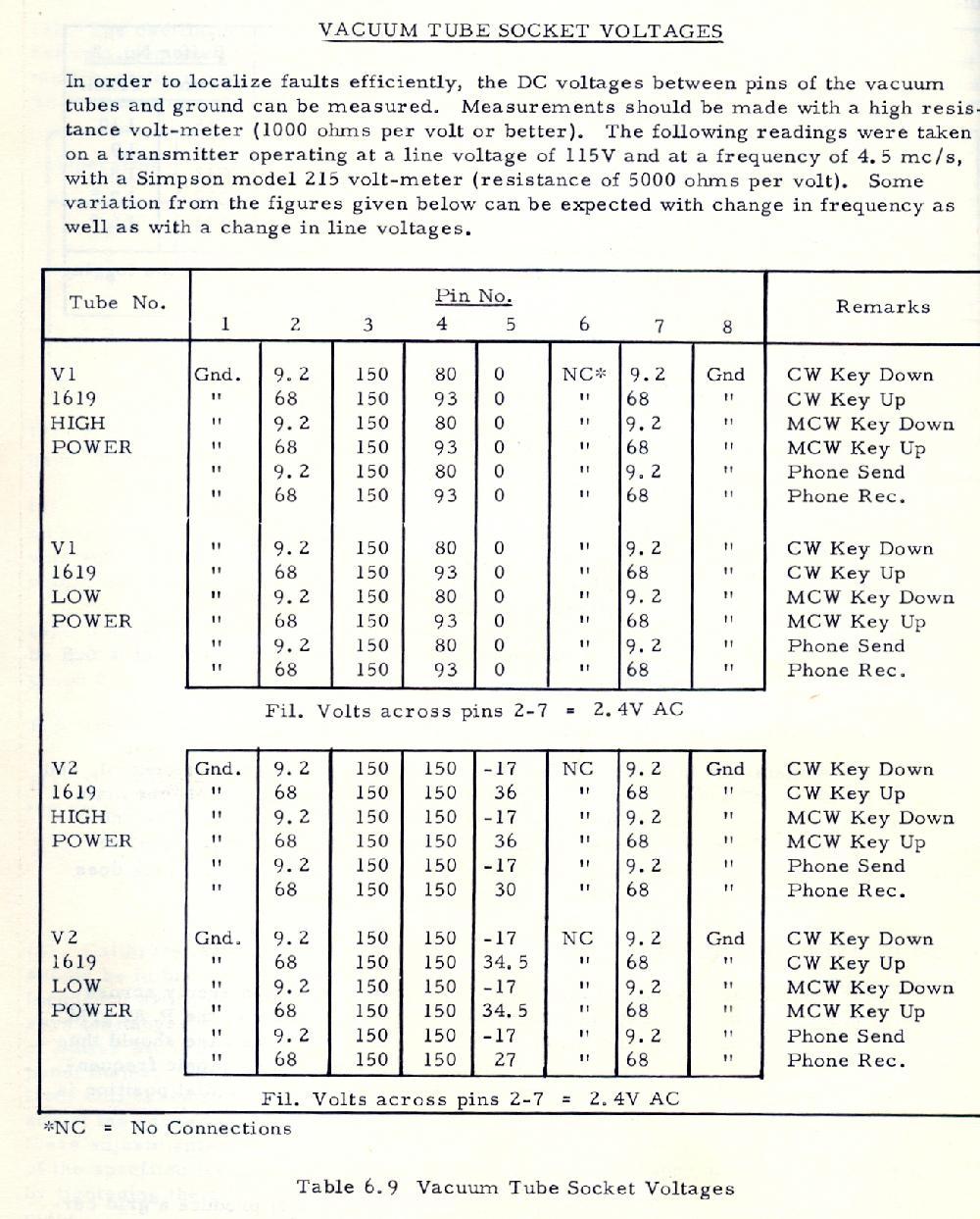
| CM11 - Votage chart #1 |
| CM11 - Votage chart #2 |
| ZM-11 Schematic - Figure 23 Left |
| ZM-11 Schematic - Figure 23 Right |
| CM-11 Internal Cabling Schematic - Figure 24 |
| CM-11 Checkout and Refurbishment Procedure by Gerry O'Hara |
OPERATIONAL INFOSo where can the CM11 be used? The unit covers the 80 and 40 meter amateur radio bands. In spite of the specification that says 13.5 MHz is the highest operating frequency, it was found in one case that the Master Oscillator would tune up to 14.15 MHz and produce a full 100 watt output on CW. There is a little chirp on the signal, but its not too bad, especially considering this unit does not have the stabilized 150v supply to the 1st buffer stage.
Here is a link to briefly hear the CM11 in operation. This CM11 is installed in a WWII era tugboat located at Saltspring Island, BC. . Here, the owner is operating at the bottom end of the 20m ham band with 100W of CW into a Butternut HF9V antenna and the received signal is being monitored using a Software Defined Reviver (SDR) located in Ohio.
RECOLLECTIONS
Gerry Taylor was a former RCN radio operator. He recalls his experiences with the CM11 transmitter
"My memory of the use of the CM-11 is pretty well limited to a only a couple of ships that I served in. I mainly used it for sending and receiving but I did have to know how to tune them up for the desired output mode and frequency. I preferred to use it mostly on CW 100 watt output. The transmitter that we used the most for Navy Traffic at sea was the PV500, which had a much higher wattage output.
The ship that I used the CM-11 on the most was HMCS Fort Erie, in 1962. On that ship, we were on a three month cruise up and down the West Coast of Africa, from Dakar Senegal to Lagos Nigeria. There were two ships on that Cruise - the Fort Erie and the New Waterford. We were supporting three Canadian Trade Fairs up and down the Coast. The ship was licensed for ham radio, and the call sign was VE0NR. Not a lot of military stuff going on during this cruise, and the CM-11 met the legal limits for ham radio operation. A few times we were able to connect with Ontario stations who made phone patches for us to family members.
As I recall, the quality of the CM11's phone mode was not that great. The reliability of the set seemed to be good. I can't remember having any technical issues occurring during use. I liked the tone of the CM-11 on CW output. On Modulated CW output, you got a totally different tone as I recall. They clunked and made a lot of noise. I cannot recall using anything other than the Master Oscillator on the CM-11. The Main Radio Room had about 3 or four work stations in a row. We would use one of the work station receivers to listen to the CW conversation..
PHONES JACK
 |
| The purpose of the PHONES jack and and its associated volume control are not explained anywhere in the CM11 manual. It is believed that the tone in MCW mode can be monitored from the PHONES jack and provide the operator with some feedback about his sending. There is no evidence to show that MCW was ever used by the RCN for communications. . (Photo by Gerry O'Hara) |
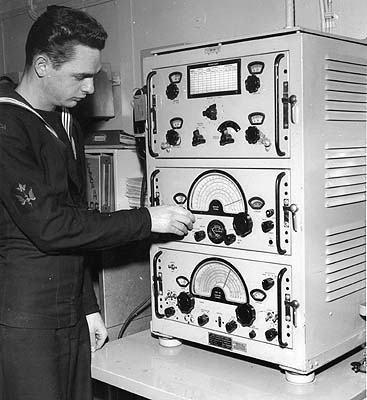 |
| Dave Blais, RCN radioman at the time, adjusts one of the CM-11 transmitters aboard HMCS Restigouche in 1959. (RCN photo from the collection of Dave Blais) |
 |
| CM11 S/N 161. Click on image to enlarge. Because this unit has a "MAN ALOFT" switch in the upper left corner of the cabinet, that means it was previously in service with the RCN. (Photo by Gerry O'Hara) |
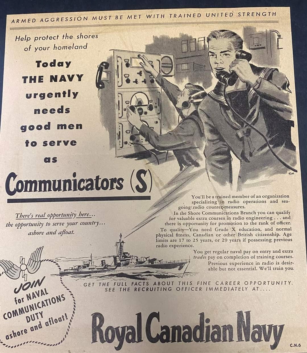 |
| This is an RCN recruitment notice circa 1950. Notet he CM11 in the background. Click on image to enlarge. The (S) means Communications Supplementary.branch. |
Spud Roscoe provides some additional information about the recruitment notice. "This is a recruiting advertisement for navy communicators in 1950 when the navy was gearing up for the Korean War. This shows an operator operating a Canadian Marconi CM11 radio station.The navy telegraphist had just been renamed a Communicator Radio. At this time, the navy recruited female members again, the first since World War II. There were three Communicator trades; Communicator Radio, Communicator Supplementary and Communicator Visual. As near as I can tell, the first female members were all Communicator Supplementary. I joined the Communicator Supplementary trade in 1956. There were no female members and they did not last long. Apparently, the navy planned to man the Communicator Supplementary coast stations with female members, so the male members could serve in the ships, as they had done during World War II. The Communicator Supplementary trade was created when the telegraphist was divided up into the two trades; namely, Communicator Radio and Communicator Supplementary.
Above the word "JOIN" in the lower left corner of the above advertisement is more or less the World War II telegraphist badge. In 1955, they were issued new trade badges. Communicator Radio still showed the wings of Mercury with an electrical flash and solid knob at the bottom where the wings joined. CommunicatorSupplementary showing the wings of Mercury with an electrical flash and bars at the bottom where the wings joined to indicate a direction finder loop antenna. Communicator Visual with two signal flags crossed by their short flag poles.
In 1960 all three trades were renamed; Radioman, Radioman Special and Signalman. They were identified with the two letters; RM, RS and SG. These three trades formed the Communications Department within the three frigates I sailed in.
Mercury is a major God in Roman religion and mythology. He is the God of messages and communication. So, his wings as a trade badge are quite appropriate. The United States Navy created their communication technician specialty in 1948, from the members of their radioman specialty that had done that work during World War II. Their radioman specialty had been created in 1921. The Communication Technician was labelled CT and the radioman RM. The Canadian RS and American CT did the same work, so much so that they used to exchange members. The RS member would go south with the U.S. Navy and the CT member would come north with the Canadian Navy. I worked with several CT Chief and Petty Officers".
Contributors and Credits:
1) Keith Kennedy <a4a88300(at)telus.net>
2) Marconi CM11 Operations and Service Manual #122-104 RCN Ref 3X/102
3) Meir Ben-Dror, WF2U <wf2u(at)ws19ops.com>
4) BRCN 2769 Instruction Book for the CM-11A
5) Jim Brewer <snack.235@sympatico.ca>
6) Denis Chouinard <denischouinard(at)enter-net.com>
7) Dave Blais <brodger0131(at)rogers.com>
8) Gerry O'Hara [gerrycohar(at)gmail.com] VE7GUH
9) daleromagnoli(at)yahoo.com
10) Spud Roscoe [spudrve1bc(at)outlook.com]
Dec 1/22