 |
 |
 |
 |
 |
 |
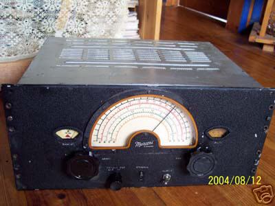
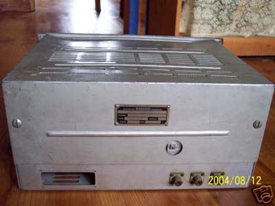
| The example in the photo appears to have many parts stripped out so it cannot be viewed as an actual example of the Common Oscillator. (All photos via E-bay) |
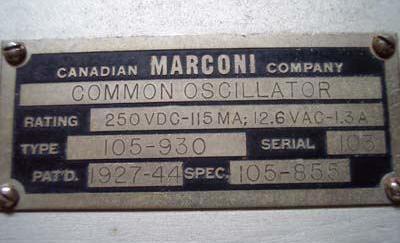
COMMON OSCILLATOR #105-930
Since there is no manual available for this device, radio collector Tom Brent provides an educated guess as to the purpose of the common oscillator. "The term common oscillator leads me to believe it may have been the frequency control for receivers set up to operate in space diversity mode. Dual or triple diversity receivers were commonly used in point-to-point communication circuits.
Note that that common oscillator has the same frequency coverage as the upper 4 bands of the CSR-5 receiver. There are 3 output connectors on the rear panel and, assuming they are original, would lead me to believe it was feeding multiple receivers. I do not know of any application where multiple transmitters at a station would be operated on the same frequency. It is believed that the common oscillator was designed to work in conjunction with a CSR5Y receiver but this cannot be confirmed at this time.".
Specifications:
Model: 105-930.
Patented: 1927-44.
Serial no: 103.
Ranges: (MHz) 1.5 to 3.5; 3.5 to 7.5; 7 to 16 and 15 to 30 MHz
Logging Scale : 1 to 23
Rating: 250 VDC - 115 MA, 12.6 VAC- 1.3 A.
Physical: 19" by 13 1/2" by 8 3/4"
Weight: 35 lbs.
Circa: Believed to be 1944
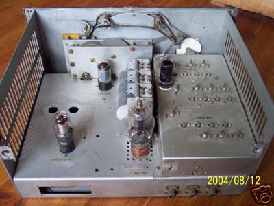
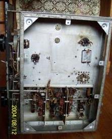
Comment: There are tubes plugged into sockets on the chassis but no components are connected. This example might have been a parts source..
|
|
|
|
|
|
| The example in the photo appears to have many parts stripped out so it cannot be viewed as an actual example of the Common Oscillator. (All photos via E-bay) |
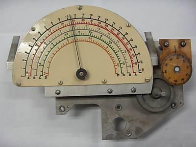 |
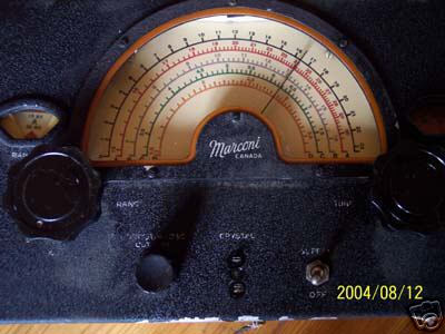
| This dial assembly has been extracted from a Common Oscillator. Note that only bands A,B,C, and D are present. . ( Photo by John VE2VX) |
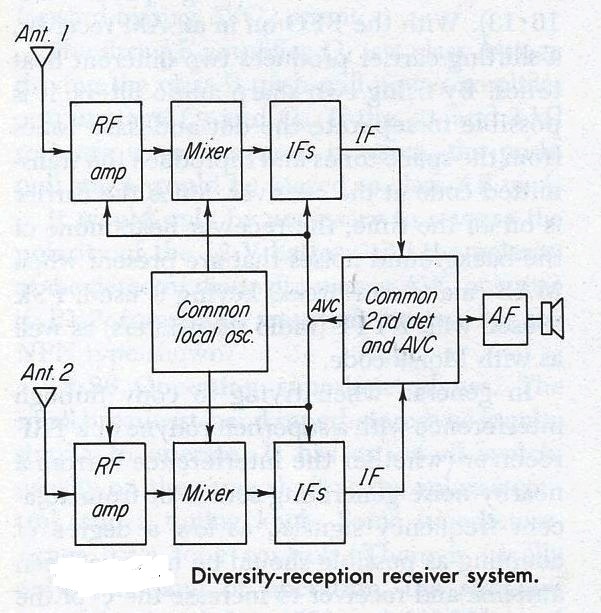 |
| This generic
diagram illustrates dual diversity reception, Two superheterodyne receivers
are connected to antennas which are some distance apart. Between the two
receivers is a Common Oscillator which contains several stages.
The Common Oscillator feeds the mixer stages of the respective receivers, Two more connections to the Common 2nd Detector accept the IF outputs from the receivers. A third connection on the common 2nd Detector stage provides an AVC output signal to each receiver. The best received signal is then passed to a common audio stage (Graphic from Electronic Communication) |
Contributors and Credits:1) Tom Brent <tgb(at)telus.net>
2) Electronic Communication 1967,Robert Shrader.MacGraw-Hill Inc
Dec 15/22