CSR-4 CSR-4A,
CSR-4B and CSR-4D Receivers
SPECIFICATIONS
Type: 15 tube superheterodyne
Modes: CW/AM
Provision is made
for two crystal controlled frequencies for spot working,
Circa: December
1938
Audio power: 5 watts
max.
AC power input:
115 VAC; 25 or 60 Hz
DC: 110 ma @ 250V
DC; 4.1 amps @ 6 VDC
Weight: 76 pounds
Dimensions:
19" wide x 10,5" high x 16.5" deep
Frequency ranges:
For CSR-4 as read
from a manual extract.
Band 1 - 13 to 30
MHz
Band 2 - 6.6 to
16.5 MHz
Band 3 - 3.15
to 7.5 MHz
Band 4 - 1,55 to
3.5 MHz
Band 5 - 175 to
375 KHz
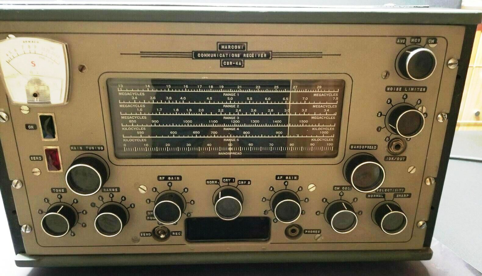
As read from the
CSR-4A dial below:
Band 1 - 13
to 30 MHz
Band 2 - 3.3
to 7.5 MHz (no coverage from 7.5 to 13 MHz. Why would CBC want a receiver
with a frequency
coverage that includes
the AM broadcast band and leaves out 7.5-13.0 MHz? )
Band 3 - 1.5
to 3.5 MHz
Band 4 - 850
to 1600 KHz
Band 5 - 540
to 1000 KHz
No dial data available
for the CSR--4B or the CSR-4Cat this time
CSR-4D
Frequency coverage:
175 KHz to 385 KHz ; 1.5 to 30 MHz
The D model differs
from the earlier CSR-4 (no suffix) as follows:
No provision for
emergency battery power is mentioned, nor is the power transformer rated
for 25 Hz AC operation.
The rectifier
tube changed to type 5Y4.
IF frequency is
455 KHz (the 1938 document procuted a while ago has 575 KHz penciled
in as the IF frequency).
Audio output stage
is a single 6K6. The earlier CSR-4 had two 6K6 tubes in a push-pull configuration.
Paint colour is
Marconi battleship gray.
The top cover
is hinged. Earlier examples seem to be lacking hinges,at the top of the
case.
The 'differences'
information was derived from the CSR-4D manual dated Feb 2/40.
A marketing document
along with a technical description can
be found here. However , the he CSR-4D schematic is missing. (Provided
by Tom Brent)
TYPES
CSR-4 receiver in
metal cabinet
75951
Dynamic speaker
in cabinet
80430
CSR-4 rack mounting
75950
Dynamic speaker,
rack mounting
75952
CSR-4 receiver,
dynamic speaker;
rack mount with 10.5 in blank panel 75953
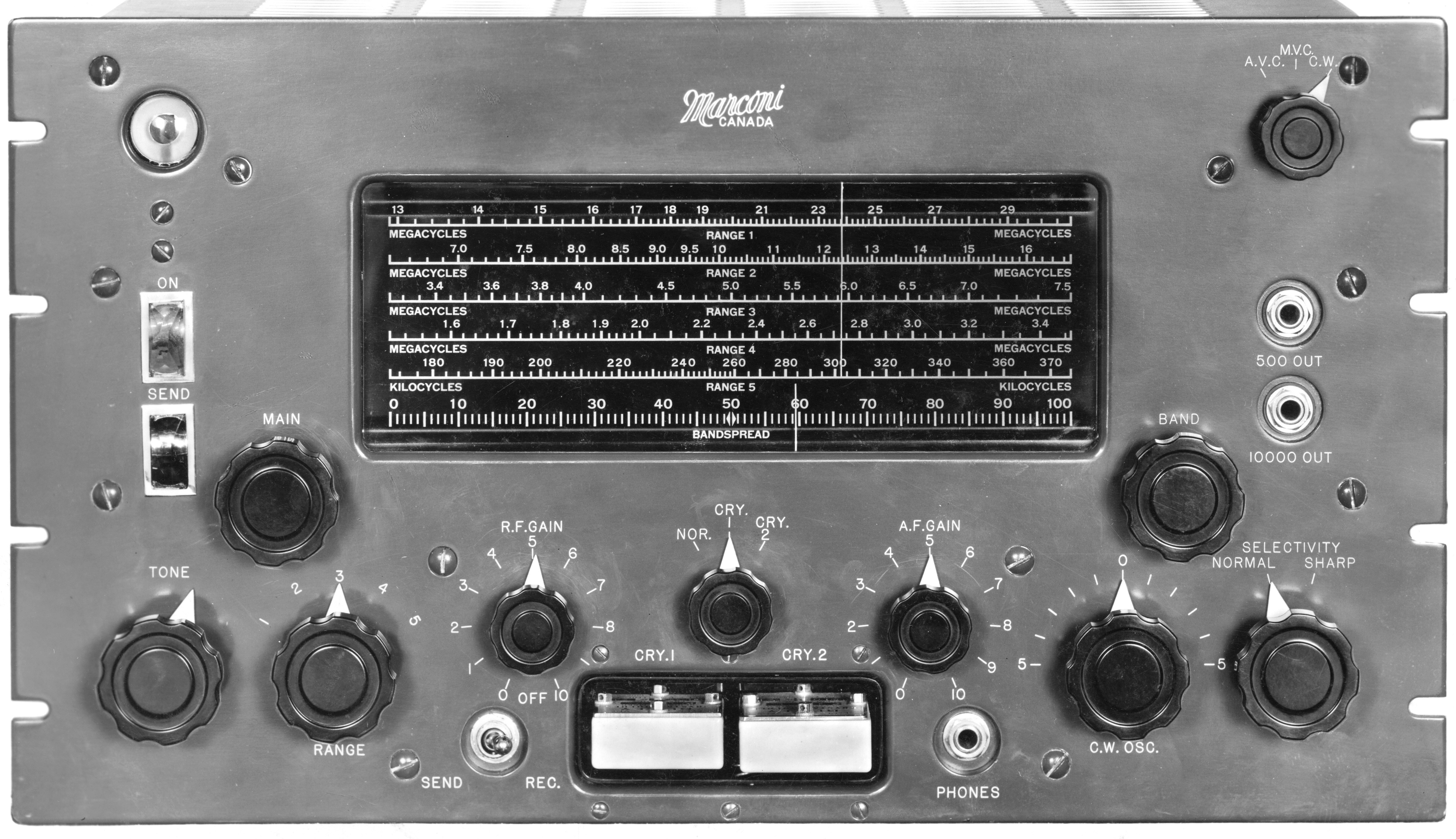 |
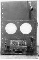
| A
high res CSR-4 front panel photo. Click on image to enlarge Photographic
evidence indicates that the CSR4 was used by the DOT, the CBC and
at the RCN's Gordon Head intercept station. (Provided by Dave
Whiting VA3QG) |
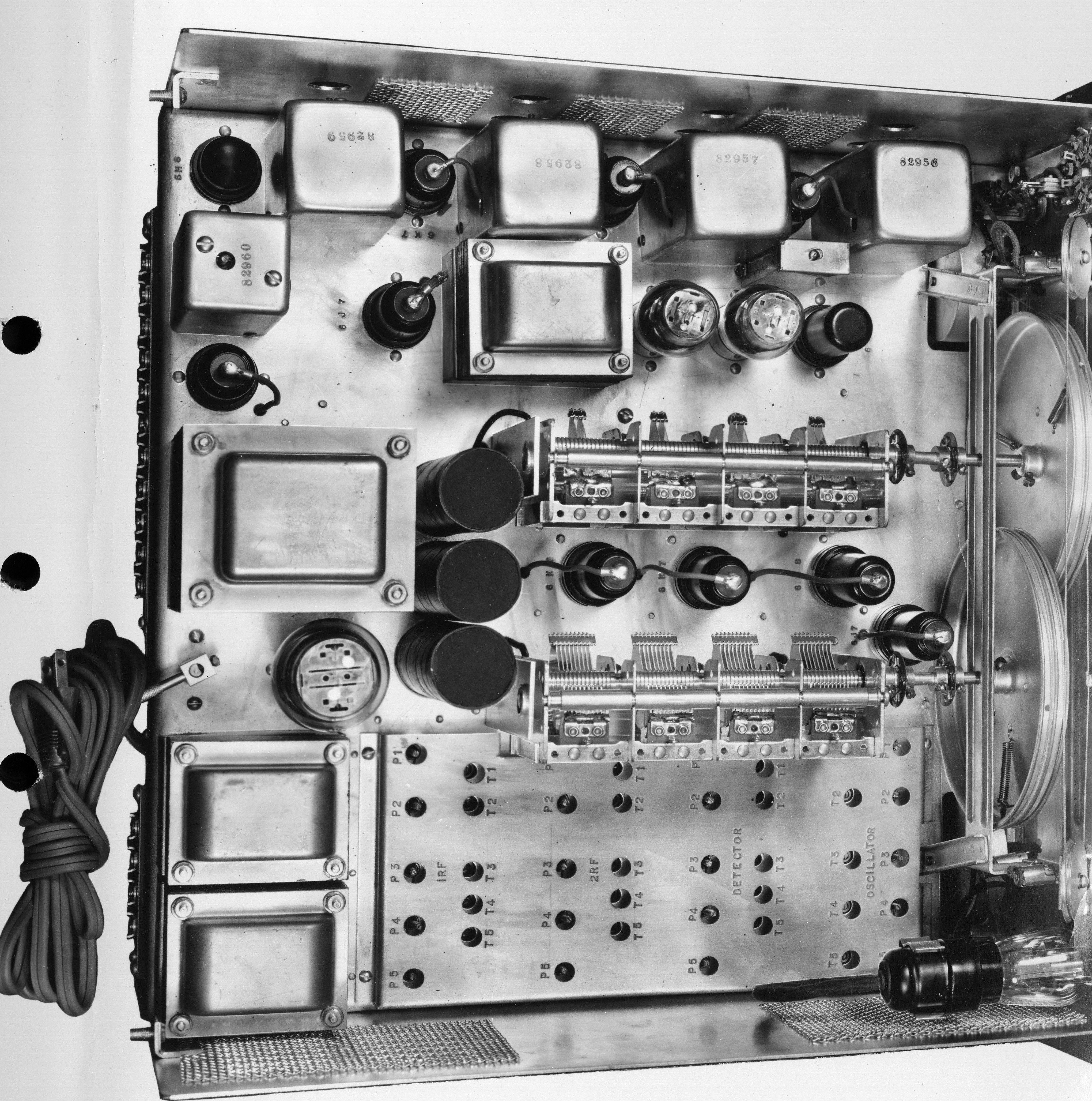 |
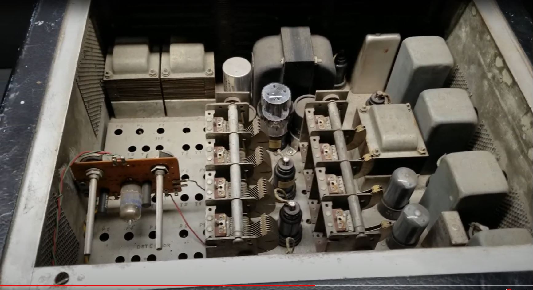
| A high
res CSR-4 top view photo from the manual. Click on image to enlarge.
(Provided by Dave Whiting VA3QG) |
Tom Brent
provides his observations after reading the nformation about the CSR4 which
has been collected to date.
1. The information
bulletin states the primary purpose of the power connections that are brought
out to the terminal strip on the rear of the chassis are for emergency
operation on batteries. That doesnt mean they couldnt be used to power
an external device but at this point we have no evidence of that.
2. I went looking
for the quick change-over switch that allowed the receiver to run on
batteries or AC line voltage. In the high resolution photo that Dave provided,
you will see what appears to be a knurled lever located to the left of
the 5X4G rectifier tube. Notice it has two slot head screws to either side
(above and below in the photo) and the lever grips a shaft with a flat
machined into it. Im quite sure this is the AC/battery switch. The screw
spacing (1.5 inch) matches what is found on a standard rotary switch and
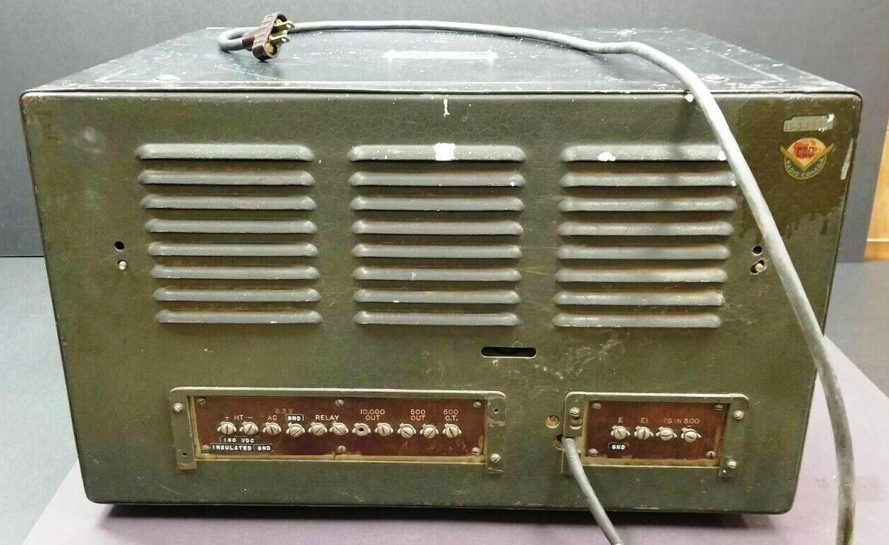
the shaft profile also jives. Further, if you look at the photo on Jerrys
webpage that shows the rear of the CSR-4A cabinet, you will see a slot
in the appropriate location for having the lever sticking out. This would
allow the switch to be operated without removing the top cover from the
cabinet if it was necessary to quickly change over to emergency power.
Presumably, when running on AC power, the switch would disconnect the hot
terminals at the back of the receiver.
3. There are some
oddities in the information bulletin. The section titled Selectivity Control
actually describes AGC switching and in the circuit description it refers
to the oscillator/mixer circuit as frequency changing rectifier.
4. The frequency
coverage of this (presumably) first model of CSR-4 is 175-375 KHz &
1.55-30.0 MHz with an IF frequency of 575 KHz. Thats a little odd in that
it didnt go higher in the MF range and cover the 500 KHz distress/calling
frequency as the CSR-5 did.
5. The CSR-4A model
seen on eBay (and Jerrys webpage) covered 530 KHz 7.5 MHz and 13.0
30.0 MHz. For a reason that will probably remain forever unknown to us,
a version of the CSR-4 was needed that would tune the AM broadcasting band
while deleting 7.5 13.0 MHz coverage. Because it tuned the AM band, the
IF frequency of 575 KHz would have been changed, probably to something
in the 455 KHz range.
6. In addition to
the SEND/RECEIVE switch that controlled plate voltage to the RF and
IF tubes, there was also a T/R relay which could be controlled by the transmitter.
7. The information
bulletin is dated 21 December 1938 adds to the timeline we have slowly
developing for the entire Canadian Marconi CSR receiver series.
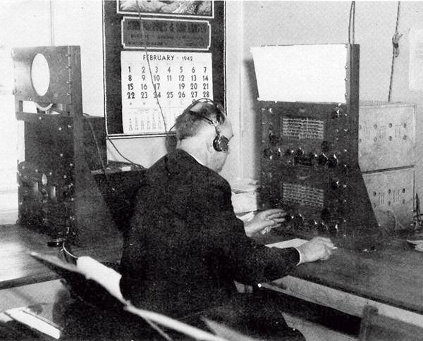 |
| February 1942: An
intercept operator at Hartlen Point, N.S. is using a Canadian Marconi CSR-4
receiver. At the left side is a Hammarlund receiver most likely the
SP-200. (Photo submitted by Laval Desbiens VE2QM) |
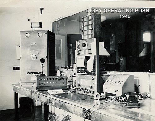 |
| CSR-4 at Digby Island,
BC. It's located second from the right at the bottom of the rack.(
Photo provided by Dave Whiting, VA3QG) |
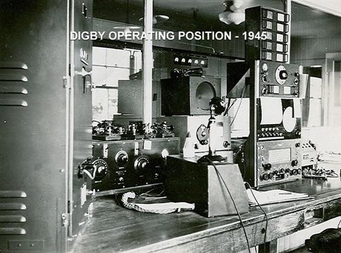 |
| CSR-4 at Digby Island,
BC It's located second from the right at the bottom of the rack.(Photo
provided by Dave Whiting, VA3QG) |
 |
| CSR-4B at station
VAU. (Photo credit - Dr. H . B . Sabean) |
CBC MONITORING
SERVICE
At this point, the
suggestion that the CSR-4 was in the service of the CBC Monitoring Service
rests solely on evidence provided by the CBC logo stuck on the back of
the cabinet. The period of use (1940 to 1958) for that particular logo
is commensurate with when a CSR-4 might have been in service with the CBC.
What is needed are some photos.
A United States Department
of Commerce publication provides a bit of background information. Established
in 1935 on 18.5 acres of land in Britannia Heights (west end of Ottawa),
the HF monitoring station was used for technical monitoring, i.e., reception
information exchanges with various broadcasting organizations directing
transmissions to North America. It was also used for program monitoring
for information and/or pickup for rebroadcast on domestic CBC networks.
For example, BBC News, certain ORTF (Paris) programs, etc. This role would
have been very active during World War II when the BBC would relay program
material created by CBC reporters who were accompanying Canadian troops
in Europe.
From the middle 1960s
on, there were increasing levels of local electrical noise due to a new
highway within feet of one of the antenna systems at the Britannia site
and encroachment of local dwellings. Antenna systems at this time included
at least 2 rhombics. When it became known in the late 1960s that adjacent
land would be developed for single family housing units and City of Ottawa
wished to build a high school on part of the monitoring station property,
a decision was made to relocate. In 1972, the monitoring station moved
to a 40 acre site in Stittsville (or possibly Carp). Receiving equipment
made by TMC, Mullard, Racal and Plessey was used at the new site. Antennas
included a Collins rotary log periodic, Hermes aperiodic loop arrays, Beveridge
and Telefunken Omni-Pole.
So, this was not
a small back-room operation and it will not be surprising if we learn they
had multiple CSR-4s as well as other types.
Contributors and
Credits:
1) Laval Desbiens
<desbienslaval(at)gmail.com>
2) Spud Roscoe <spudroscoe(at)eastlink.ca>
Deceased as of Dec 20/23
3) Arthur Crowell
<af(at)ns.sympatico.ca>
4) Gerry O'Hara
5) Dave Whiting
VA3QG <Barbar3380(at)outlook.com>
Back
to Equipment Listing
May 2/24