CSR-5 and CSR-5A
Receivers
BRIEF HISTORY
The RCA AR-88 receiver
had been approved by the Inter-Service Committee on Design as a general
purpose communications receiver in WWII but that did not stop the
Canadian Navy from placing orders for the Marconi CSR 5 receiver instead
of the AR 88. Between March and August, 1943, this Service ordered
a total of 740 sets. New Zealand also placed an order for 100 of
the sets. At the end of August, 1943, No CSR 5 receivers had been delivered,
although original forecasts were set for July. The latest forecast
for start of deliveries was rescheduled to December, 1943. Many CSR's were
placed into monitoring service at Special Wireless Stations which intercepted
German U-boat traffic. Special Wireless Station Coverdale near Moncton
was one such location. Post war production quantity is not known
at this time.
Some additional information
on the CSR5 can be found on pages
49 and 50 of the Signals Production Branch document dated October 15,
1943.
 Women's
Royal Canadian Naval Service (WRCNS, pronounced WRENS) operators are using
Marconi CSR5 receivers at Special Wireless Station Coverdale in 1944. The
receivers were manned in three shifts of 8 hours each. No one liked the
graveyard shift or the ersatz coffee which helped to keep everyone
awake. (National Archives Canada photo # PA 204141) Women's
Royal Canadian Naval Service (WRCNS, pronounced WRENS) operators are using
Marconi CSR5 receivers at Special Wireless Station Coverdale in 1944. The
receivers were manned in three shifts of 8 hours each. No one liked the
graveyard shift or the ersatz coffee which helped to keep everyone
awake. (National Archives Canada photo # PA 204141) |
In peacetime
and aboard Her Majesty's Canadian ships, many CSR-5's spent their working
life receiving the Fleet Broadcast sent in Morse Code at 22 wpm or guarding
the International or marine distress frequencies. Each receiver was connected
to its own wall mounted speaker, but headphones were the order of the day.
Loudspeakers were used when one Radioman had to guard more than one frequency.
This was known as a loudspeaker watch.
 |
| MASS PRODUCTION:
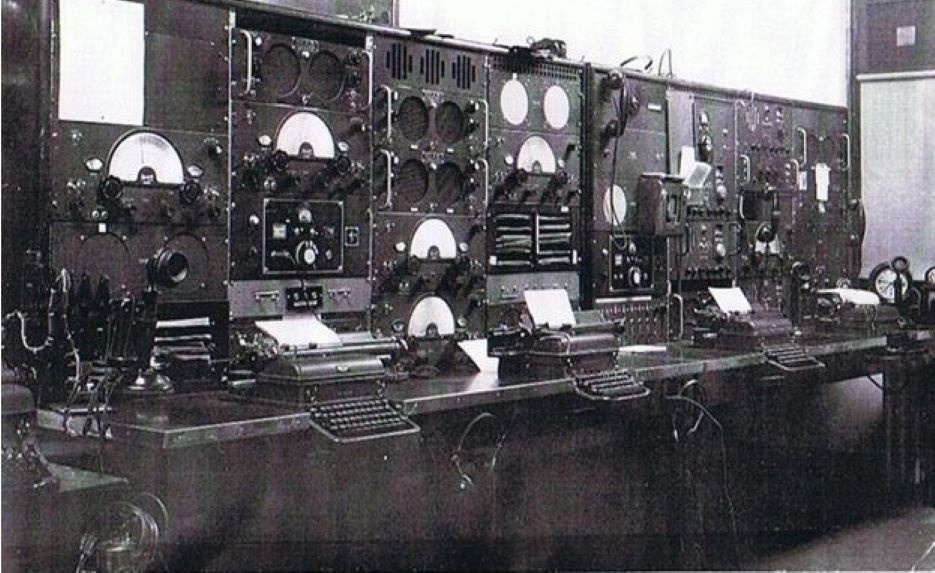
Fifty-three men could be accommodated at one time in the instructional
receiving room, used for training basic classes in typing and Morse at
the RCN Communications School at HMCS Cornwallis, Nova Scotia. At a later
date, it was planned to expand to a Morse pool, with all exercises run
from a central control room. Where else can one see so many CSR5's all
at once? Cornwallis is now closed. (From Crowsnest, May 1952.
RCN photo DB-1301-1) |
 |
| Five CSR5 receivers
were installed at Vancouver Aeroradio in 1946. (Photo provided
by Tom Brent)
It is believed that
during World War II, the Department of Transport placed an order for BLACK
rack-mounted CSR-5s, type number 110835W. These are not common but there
are a few that have turned up over the years. Records show six of them
with serial numbers ranging from 198 to 388. Radio collector Tom
Brent owned two of them and still has S/N 198. His belief is that Marconi
supplied them directly to DOT is solely based on the fact they can be seen
in numerous DOT station (marine and air) photos but none have ever been
seen in any RCN photos. |
 |
| Serial
466 is one example on display aboard HMCS HAIDA. By 1969, the CSR-5 series
was considered obsolete and was taken out of service in the RCN. Other
than cleaning, no effort was made to restore the front panel of this receiver
because it shows what controls were used the most while the set was in
service. (Photo by Jerry Proc) |
TECHNICAL
First designed
by Canadian Marconi in 1942, this general coverage receiver was capable
of receiving AM and CW signals in the low and high frequency bands Accuracy
was 0.5 % at any frequency.
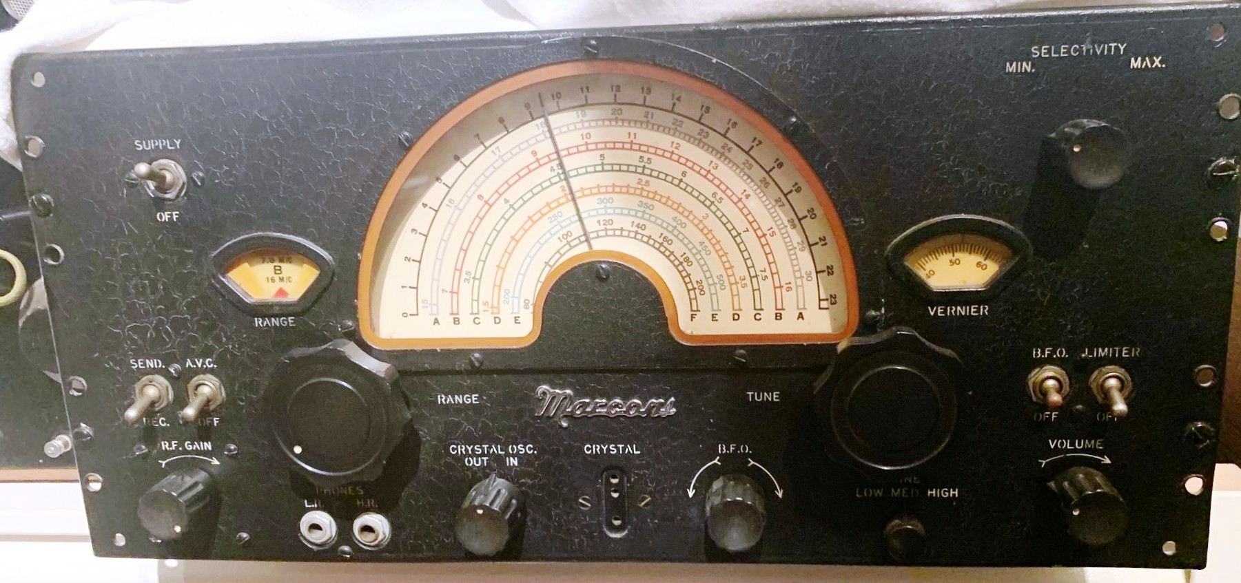
DIALS and LOGOS
The band colours
that the manual refers to are those observed in the RANGE window.
Band A on the dial, although designated as Mauve, is light gray in appearance
on the dial itself in some receivers.
|
BAND COLOURS
FROM THE MANUAL
|
| DESIGNATOR/COLOUR |
COVERAGE |
| Band A - MAUVE |
14.9 to 30.3 MHz |
| Band B -
RED |
6.8 to 16/1 MHz |
| Band C -
GREEN |
3.55 to 7.65 MHz |
| Band D - ORANGE |
1.5 to 3.5 MHz |
| Band E - BLUE |
195 to 518 KHz |
| Band F - BROWN |
79 to 207 KHz |
 |
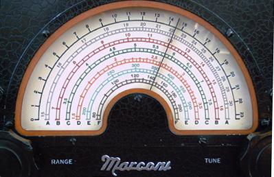
| In some receivers,
the band colours for Bands A and B are reversed depending whether the dial
has a single or dual line pattern. This is an example of a dual line pattern.
(Photo
by Jerry Proc) |
For whatever
reason, when Band A in the RANGE window is MAUVE, it does not have
the corresponding colour on the dial. Instead of mauve marking
on the dial, it is light gray. Other variations of dial colours/markings
are noted in the table below.
| Single-line
band marking, where the colors are: |
The
dual-line dial pattern where the colors are: |
Band
A: Red
Band B: Gray
Band C: Green
Band D: Yellow/orange
Band E: Blue
Band F: Brown |
Band
A: Gray
Band B: Red
Band C: Green
Band D: Orange
Band E: Blue
Band F: Brown |
Generally
the receiver dial follows the colour scheme in the above table , howewer
CSR5A S/N 842 is a single line track dial with Band 'A' being gray and
'B' being red.
 |
| This photo underscores
the colour mismatch between the Band Indicator 'A' in the RANGE window
and the dial itself. (Photo by Jerry Proc) |
 |
| After examining
nine receivers, finally one is found with a real mauve marking for band
'B'. (Photo by Jerry Proc) |
The single-line
half moon pattern was found on CSR-5Y s/n112 and CSR-5A s/n 712 (RCN reconditioned
2-64) and originally on CSR-5A s/n 904 (with one with the peeled-off dial,
below), so it doesn't appear to be related to serial number.
The RCN made a custom
modification to their receivers, The "F" band (79 to 207 KHz) was adjusted
10 KHz low to enable the reception of the broadcast frequency of 73.6 KHz.
This frequency is still assigned to Maritime Command as of 1994.
In marine service,
one of the noted quirks of the CSR 5A was the habit of going off frequency
in rough weather. If a large wave hit the ship, it would overcome the friction
of the tuning gear assembly and knock the dial off frequency. There were
no such things as frequency synthesizers or phase locked loops in those
days.
The receiver features
a 4 position crystal filter and noise limiter. To protect the receiver
and especially in shipborne applications, there is a gas discharge tube
between the antenna terminal and ground. Strong wind, moving across a ship's
wire antenna, will eventually generate a rather large static charge which
can damage a receiver's front end. The gas tube flashes over once the voltage
level reaches 100 volts.
 |
| S/N 103, painted
in black, has the "raised" Marconi logo which seems to have been
replaced with stencilling in later production runs. (E-bay photo) |
 |
| The intent of this
photo is to illustrate the block lettering on on the front panel bezel
(Photo
by Rob Moffatt) |
SPECIFICATIONS:
* Designators: Marconi
CSR-5A #110-930A . RCN Ref 3A 107-1
* Antenna Input
Impedance: 70 to 500 ohms.
* Frequency range:
79 KHz to 30 MHz in 6 bands excluding the broadcast band.
* IF Frequency:
575 KHz
* Frequency control:
Variable oscillator or crystal.
* RF Gain: Step
type control. 4 db attenuation per step at low end and 20 db per step at
high end.
* Crystal filter:
4 position. Bandwidth info not provided in manual.
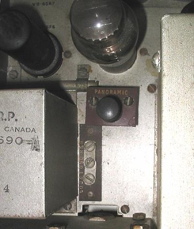
* Panoramic Display
: Supports panoramic displaay via internal connection.
* Audio Output:
4 watts. Supports 10,000 ohm speaker with transformer input or 500
ohm line or high
impedance
headphones.
* Case dimensions:
20.25 in wide x 10.5 in high x 15.25 in deep
* Weight : 68 pounds
with case; 58 pounds when rack mounted (power supply weight not included)
* Delivery start
date: post August 1943 (?).
* Production: Mostly
in 1944
* Applicable manual
BRCN 2767 for CSR5A Type 110-930A
* Shockmounts: Barry
Corp., Watertown, Mass. p/n C2080-5
TYPE NUMBERS
There are six
CSR-5 receiver type numbers that we are aware of:
105865 CSR-5Y
110480Z CSR-5 receiver
used in CM-ll transmitter-receiver
110480AZ CSR-5A
receiver used in CM-l1A transmitter-receiver
110835W CSR-5 receiver
19 inch rack mount with dust cover (no cabinet) - all known examples are
painted wrinkle black
110930Z CSR-5 stand-alone
receiver in desktop cabinet
110930AZ CSR-5A
stand-alone receiver in desktop cabinet
Type numbers 110480Z
and 110480AZ were serial numbered sequentially, The changeover from
CSR-5 to CSR-5A
came somewhere between serial number 350 and 384. The highest serial
number I have for
this type is 399. The same holds true for type 110930Z and 110930AZ where
the changeover came
at or after serial number 816 and the highest serial number located thus
far is 1070.
The CSR-5Y was used
as part of a diversity receiving system. All known examples of type 110835W
are not painted wrinkle blacc.
PANORAMIC DISPLAY
The CSR5 receiver
supports a connection to a panoramic display, however Canadian Marconi
did not suggest any specific panoramic type. Since the CSR5's IF is 575
KHZ, it may be difficult to locate a display which is capable of
displaying that IF frequency. One approach might be to use a panoramic
display that operates at the more popular 455 KHZ IF, It is suggested that
a broadcast band (BCB) receiver be used as an IF "down-converter"
which will shift the IF frequency from 575 KHz to 455 KHz.. Using
a BCB receiver with a 455 KHZ IF, connect or couple the panoramic
display output on the CSR5 receiver to the antenna input of the BCB
receiver. Then tune the BCB receiver to 575 KHz. Next, couple the
455 KHZ BCB IF to the input of the panoramic display. This is technique
is unproven. It's presented here as a concept only. .A block diagram of
the down-converter setup can be found here.
It is believed that
the only possible application for a panoramic display would have been for
CSR5 receivers installed at Canada's former signals intelligence stations.
However, no evidence has ever surfaced to support that theory. There
would be little, if any, use at any shore station.
CSR-5 vs CSR-5A
One commonly asked
question is the difference between the CSR-5 and CSR-5A. Firstly, the changeover
from CSR-5 to -5A came somewhere between serial numbers 350
and 384 in the CM-11 receivers (type 110480). The change from CSR-5 to
CSR-5A (in desktop types 110930) came at serial number 816 or 817. The
specification number is the identifier for a schematic wiring diagram.
Radio collector Tom
Brent comments " I have seen so many modifications and "hatchet-jobs" to
these radios which only offer confusing clues but there are few items on
the comparison list that unmistakably identify a CSR-5 from a CSR-5A. As
originally manufactured, it is impossible to put a CSR-5 in a 5A cabinet
and vice versa but I have seen numerous -5A cabinets with locator pins
cut out to enable a -5 to be installed as well as -5 cabinets with the
power connector opening enlarged to allow installation of the -5A receiver.
I have seen crystal filter covers (which bear the part number) that have
obviously been switched, audio transformers changed and many dial escutcheons
with labeling that doesn't jive with what is behind the pane. lMany of
the early CSR-5s had the serial number rubber stamped on the side of the
chassis and this agreed with the S/N on the ID plate attached to the dust
cover.
The escutcheon is
a leading source of confusion as to whether a receiver is a -5 or a -5A.
In the 1950's and 1960's the escutcheon was repainted and silk screened,
part of a refurbishing program that many CSR-5's and CSR-5A's went through.
Some escutcheons
were simply painted black and some were painted black and silkscreened
or stencilled with the CSR-5A designation. The is no evidence so far of
any repainted dial escutcheon with "CSR-5" (non "A") script on it. So,
to set the scene here - At an RCN overhaul depot with perhaps dozens of
radios being refurbished, putting a CSR-5A dial escutcheon on a CSR-5
receiver could easily have happened and would have no operational or technical
consequence. What they didn't consider was that 50+ years later, someone
who would lovingly restore the receiver might be confused as to what model
they actually had.
Somewhat unique is
that some CSR-5 receiverst have an "alligator finish" paint job and a chrome
"Marconi" badge on the front panel. This badge was used on the Canadian
Marconi CN-36U marine radiotelephone and other sets of the late 1950's.
One photo in the
web page is important because it bears a label stating it has been "SERVICED
BY CANADIAN MARCONI COMPANY". Unfortunately again, the photo isn't clear
enough to read the rest of the text. Also important to note, is that both
receivers have front panel labeling that has been silk screened but note
that it is unlike the silk screening script seen on all other CSR-5's.
Both receivers have grab handles removed and S/N 103 was intended for use
in a 19-inch rack.
Putting all these
little bits of information together, it is possible to guess as to what
might have happened with these receivers. Sometime in the 1950's, Canadian
Marconi saw a market, or perhaps received a request, for reconditioned
CSR-5 receivers. To gear up to produce new receivers would not have been
practical. Used ones were plentiful. Front panels were stripped, repainted
and relabeled. It is known that that silk screening a front
panel is not cheap, nor a practical way to use this technique for one-off
restorations. For Canadian Marconi however, they could probably do it in
house. Besides, what alternative would they have for labeling the panel
and have it come out looking professional? To make the receivers
look even more spiffy, the chrome Marconi badge was added to the front
panel but note that it was mounted level, rather than at an angle
as originally intended. Thus, the letters appear to be falling over. Because
this was a somewhat "new' receiver, Canadian Marconi decided to assign
a type number and thus the serial numbering had to start at #101. So why
was the serial number rubber stamped and the familiar etched metal ID plate
not used? Probably it was a matter of economy. Few people would ever see
or care about the serial number so a rubber stamp was adequate. Again,
gearing up to produce an entirely new etched metal ID plate for a small
order was not practical.
Many years ago I
started thinking about CSR-5's in terms of the type number. For example,
receivers installed in a CM-11 receiver transmitter cabinet were type number
110-480 and stand-alone receivers in a desk top cabinet were type number
110-930. Receivers intended for rack mounting were 110-835. In the
early years of digging into CSR-5 history, a large quantity of serial
numbers were amassed but they did not make sense at the time.
To summarize, each
CSR-5 type number has its own serial number series.
CSR-5 Type 110-480Z
- receiver mounted in CM-11 transmitter receiver.
The change from
CSR-5 to CSR-5A (110-480AZ) came somewhere between serial number 350 and
384.
CSR-5 Type 110-930Z
- receiver mounted in a stand-alone cabinet.
The change from
CSR-5 to CSR-5A (110-930AZ) came at or after serial number 816
Does the sequence
of type numbers indicate the order in which each CSR-5 model was introduced?
It may but there is insufficient evidence to substantiate that. However,
existing documentation does state there was a CSR-5 model prior to introduction
of the Type 110-480 (the lowest currently known Type #) and the receiver
in the CM-11 was adapted from it There is one more minor thing about
the receiver with the chrome Marconi logo (S/N 103). it would appear that
as part of the refurbishing it entailed the changing of the power
connections on the rear of the chassis to a single six-contact Jones plug.
Originally it had been two plugs (2-pin and 3-pin)."
 |
| A
typical Navy "reconditioned" sticker from 1963. (Photo by David Noon) |
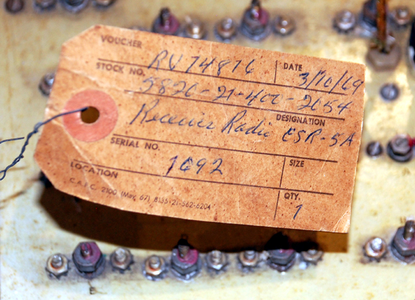 |
| A
repair tag from March 1969 (Photo by Jerry Proc) |
The 6SK7
vs 6SG7 tube issue still remains, at least in my mind, somewhat confused.
There is the clear notation in the CSR-5 manual that states (contrary to
what is shown elsewhere in the manual) 6SG7's have been substituted for
V2 and V4 during the production run. Further, most of the CSR-5's I have
encountered have had the original "6SK7" labels removed or scratched out
and, in almost all cases, neatly relabeled "6SG7" with a rubber stamp.
This could possibly indicate it was done at the factory although I suppose
the repair depots could also have been issued with a rubber stamp. Curiously
however, we still find this haphazard relabeling on the CSR-5A. I would
have thought that if they could change the silk screen used to print the
dial escutcheon and panel labeling, surely they would also change the one
used to label the chassis. But who knows, maybe in the flurry of wartime
activity at Canadian Marconi someone forgot to institute the change and
the chassis was still being produced with the "6SK7" label at V2 and V4.
However, there are
a few items that are almost impossible to change and provide a good method
of establishing the actual model type:
1. The locations
of the power switch and selectivity control are centered 1 1/2 inches below
the top of the panel on a CSR-5 and 2 inches below the top of the panel
on a CSR-5A.
2. A CSR-5A has 3/8"
holes in the top corners of the back wall of the chassis (to accept locator
pins in the cabinet); CSR-5's have no such holes.
3. A CSR-5 has a
2-screw terminal strip adjacent to the audio transformer; the CSR-5A version
has a 3 terminal strip.
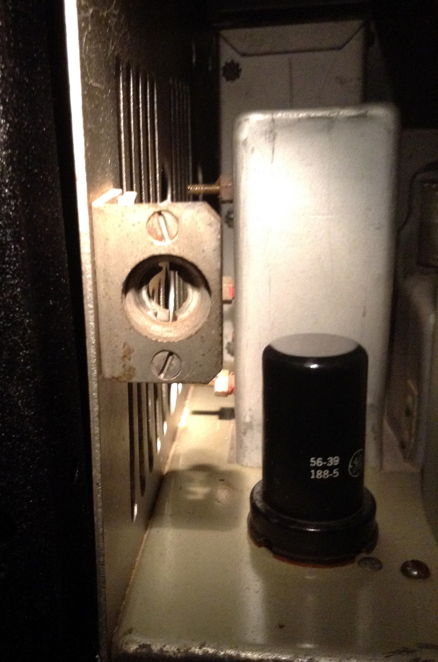
4. A CSR-5A has adjustable
slugs for band E and F RF coils that are mounted on an add-on plate affixed
to the top of the RF chassis (back-left corner); CSR-5's have no adjustment
for these coils".
|
COMPARISON OF
CSR-5 TO CSR-5A
|
| |
CSR-5
|
CSR-5A
|
| 1 |
Crystal
filter assembly is CMC part # 106-820. Selectivity control knob offset
from shaft or rotary switch. |
Crystal
filter assembly is CMC part #106-852. Selectivity control knob in line
with shaft of rotary switch. |
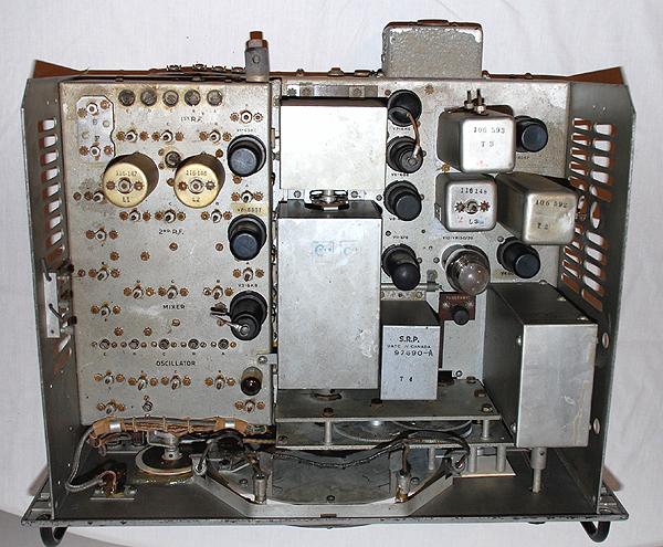
| 2 |
Audio output transformer
is CMC part #97690 |
Audio
output transformer is CMC part #97690A |
| 3 |
V2 (2nd RF) and
V4 (1st IF) type are 6SK7 See note 1 below table |
V2 (2nd RF) and
V4 (1st IF) type are 6SG7 See note 1 below table. |
| 4 |
C16, C39, C57, C69
rated at 200 volts. |
C16,
C39, C57, C69 rated at 400 volts. |
| 5 |
C84, C92, C116,
C118 rated at 200 volts. |
C84,
C92, C116, C118 rated at 300 volts. |
| 6 |
C98 26pf
C108 25pf |
C98 30pf
C108 21pf |
| 7 |
L12
CMC part #106-586. See note 2. L13 CMC part #106-587 |
L12 CMC part #106-692.
See note 2.
L13 CMC part #106-693 |
| 8 |
C133
and C134 |
C133 added to coil
L28 (OSC. C)
C134 added to coil
L29 (OSC. D) |
| 9 |
R22: 70K OR 25K
R27: 400 OR 500
R34: 400 OR 500 |
R22: 25K?
R27: 100 TO 400
R34: 400 ohm |
| 10 |
|
R62: 10K detector
damping resistor added to L20 (1ST DET. BAND A) |
| 11 |
Front panel
Amphenol crystal socket only fits one size (type BY) of crystal. |
Front
panel Amphenol crystal socket fits two sizes of crystals on part
of the production run. |
| 12 |
R58 load matching
resistor on J2 is permanently grounded. |
R58
connected to link for grounded/ungrounded option. |
| 13 |
Power
connectors are perpendicular to rear of chassis (oriented to rear). |
Power
connectors are parallel with rear of chassis. One is oriented up and one
oriented right. |
| 14 |
Lines on dial for
each band are single solid line. Band A line is RED. Band B line is
MAUVE. |
Lines
on dial are doubled (like a railway track). Band A line is MAUVE.
Band B line is RED. |
| 15 |
Cabinet has vent
holes in top, sides and back. |
Cabinet
has vent holes in back and side only. |
| 16 |
Two L-shaped brackets,
attached to back of cabinet hold down top of radio chassis. See Note 3. |
Two
locator pins welded to the rear of cabinet engage holes in rear wall or
radio chassis. |
| 17 |
Single finger pull
hole in lid of cabinet. |
Two
finger pull holes in lid of cabinet. |
| 18 |
The
audio output transformer 500 ohm winding has a two screw terminal board
to optionally ground the center tap. |
The
audio output transformer has a three screw terminal board, which also provides
a 250 ohm tap option. |
| 19 |
C123
(2,000 mmfd., 500 volts) failing in service. With few exceptions, receivers
up to serial number 816 have this condenser incorrectly connected from
terminal 4 to terminal 6 of the output transformer T4, as shown in Canadian
Marconi wiring diagram 111-900. |
C123
is correctly connected from terminal 4 to terminal 5 of transformer T4
in receivers S/N 816 and up. Also see note 4 below table. |
|
Comparison table
courtesy Tom Brent with additions by Meir Ben-Dror and Jerry Proc
|
Note 1:
V2 & V4 are shown on the CSR-5 parts list as type 6SK7 and on the CSR-5A
parts list as type 6SG7. On all CSR-5 and CSR-5A receivers viewed so far,
the tube position and type numbers were originally silkscreen printed onto
the chassis. In all but one example of the radios seen so far, it appears
that the original number (6SK7) at the V2 & V4 position has been removed
and a new number (6SG7) added with a rubber stamp using black ink. The
one exception is a CSR-5 (serial # unknown) which retains the original
silk-screened 6SK7 at the V2 and V4 position. Of all the changes, this
is the most significant one because it affects the fundamental operation
of the receiver. Here is the official notification taken from the manual:
" In order
to provide increased maximum sensitivity, the 6SK7 valves V2 and V4 have
been replaced by the 6SG7 valves. This change has resulted in an improved
AVC characteristic over the range from 10. to 100,000 microvolts. So as
to exploit this feature, certain changes have been made to the circuit
and these are shown on the schematic diagram".
Note 2:
L12 & L13 are the RF input coils for the two low frequency bands, E
& F. They are not adjustable on the CSR-5 and thus adjustment screws
do not extend through the top of the RF chassis. On the CSR-5A, these coils
are repositioned and mounted on a small plate attached to left-rear corner
of the RF chassis. They are adjusted in similar fashion (from a position
above) to the other bands. This provides one of the easiest ways to recognize
a CSR-5A.
Note 3: A CSR-5 receiver
cannot be installed in a CSR-5A cabinet because the locator pins protruding
from the back wall of the later cabinet prevent the earlier receiver from
sliding all the way in. Conversely, a CSR-5A receiver will not fit in a
CSR-5 cabinet because the power supply connectors require a larger opening
to clear the back wall of the cabinet.
Note 4 : RCN Naval
Serice (NS) Order 1008-78-1 dated Sept 9, 1944 requests (in part) that
"Each receiver in service, or being placed in service, with serial number
below 816 is to be checked. Condenser C123 is to be connected from terminal
4 to terminal 5 of transformer T4".
From the available
data, the following patterns are in evidence. CSR5's saw three forms of
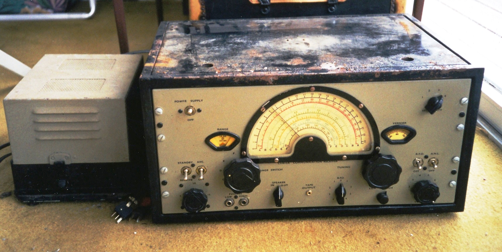
service:
1) Receivers for
rackmount operation. These would be supplied with the WE-11 (AC only) rack
mount power supply and a protective cover. (It's too early to conclude
if all rackmounted CSR5's and including the 'Y' variant came in black).
2) Receivers for
standalone operation. These would be fitted in an vented enclosure and
come with the standalone VP-3 AC/DC power supply.
3) Receivers destined
for CM11's transmitters. These of course, would not come with any enclosure
or either of the above power supplies.
Layered over top
of that would be the phasing-in of the CSR5A model at some point in the
production cycle and the various colour schemes discussed elsewhere in
this document.
RECEIVER SERIAL NUMBERS
A big irritant in
this receiver is the fact that many units do not have a serial number plate
affixed to the left side of the chassis. It appears that serial number
namplates were affixed to the top of the case and not the receiver iteself.
Therefore, in a repair facility with multi CSR5's to repair, it would be
in the realm of possibility that receivers and cases might get mixed up
if the technicians were not careful.
Radio collector Tom
Brent speculates on at what serial number serial number the model '5A was
introduced. " I have CSR-5 serial numbers as high as 671 and CSR-5A numbers
as low as 399. This indicates 2 possibilities, the first being that CSR-5
serial numbers started at 1 and went up to 671 (the highest number I have
found so far) and possibly beyond. The second part of this scenario has
CSR-5A numbers also starting at 1 and going up to 973 (the highest CSR-5A
that I have found so far). Lets round the highest numbers off a little
and say that they produced 700 CSR-5s and 1000 CSR-5As. Does it seem
logical that the navy would have ordered that many in total? Does it seem
reasonable that Canadian Marconi could have produced that many?
I believe there is
a second possibility for the serial number question. Canadian Marconi could
have employed a numbering system whereby the receivers shipped in cabinets
were one series and the receivers included as a part of CM-11s were another
series. The information supplied by the numbers I have tabulated so far
does nothing to disprove this theory and there is even some information
to back it up but I need data from more radios before I can reach a conclusion".
As for the production
run, serial 103 is the lowest one logged so far with Serial 1024 being
the highest in the range. Any other contributions are most welcome. Contact
jerry.proc@sympatico.ca . Please provide the following information:
1.
Where is the I.D. plate located? ie Cabinet or chassis?
2.
Serial number ?
3.
Type number (the WHOLE number)
4.
Specification number (sometimes missing)
5.
Pattern number (usually missing)
6.
On some early sets, the information is rubber-stamped with black ink onto
the side panels (close to where they meet the front panel)
7.
Colour and finish is the front panel?
To add another element
of confusion, some CSR-5As have an I.D. plate that identifies them as
a CSR-5! Some CSR-5 receivers also have a dial escutcheon that says
"CSR-5A". It is possible that during refinishing (in the 1950's???) some
dial escutcheons were silk screened with the script "CSR-5A" and then slapped
on whichever receiver was being refurbished(?).
Webmaster's note:
As of March 2014, the higest CSR5A serial number is 1062.
POWER SUPPLIES
VP3 - AC/DC Supply
# 110-540 RCN Ref 3D/101
This supply provides
the following voltages to the receiver:
250VDC at 110 ma
and 12.6 VAC at 3 amps.
The VP3 power supply
for the CSR 5A was designed to operate from 115/230 volt 25/60 Hz AC power
or 12 VDC. When switch over to DC power, Marconi designed two interlocks
to ensure that no damage could be caused by inadvertent operation on the
wrong power source. To switch from AC to DC operation, a five pin interlock
plug had to be moved from one socket to another. Subsequently, the AC line
cord had to be disconnected from the wall socket and inserted into a special
chassis mounted receptacle. One of the prongs caused a switch to open up.
VP3 power supplies also acquired a reputation for fusing the contacts on
the vibrator thus frying the primary winding on the power transformer.
The VP-3 power supply
came in two versions. One version covers S/N 101 to S/N 1200 while the
other covers 1200 and up. Two major differences are observed when the schematics
are compared. The part number of choke L4 is different. For the older
serial number range, the part number was 116-277 while the newer
range is #97704. Also, the position of F2 was moved. In the newer
series, it now protects the AC input directly instead of being in series
with F1 in the DC input line.
 |
| VP-3 with cover
off. Note the mauve bakelite plug which is one of three interlocks for
AC or DC operation. When used with DC, the AC plug must be removed from
the wall receptacle and inserted into the socket to the left of the rectifier
tube. Then the bakelite plug must be moved from the AC to the DC socket.
Lastly, a toggle switch (locked with a metal bracket) must be flipped to
the DC position. (Photo by Greg Farrell) |
 |
| VP-3
bottom view. Note the copper-clad matte finish chassis. This VP-3 came
with a service tag indicating that the unit had been installed in HMCS
Fundy 159 in January 1964. (Photo by Greg Farrell) |
 |
| This
is how the spare vibrator fits into the cover. (Photo by Greg Farrell) |
 |
| The Marconi VP-3
power supply is at the right and a near replica built by Jerry Proc VE3FAB
on the left. The VP-3 It is not wearing its original deteriorated light
gray crackle paint finish since it had been repainted with Tremco Grey
Rustclad paint. (Photo by Jerry Proc) |
 |
| Another view of
the VP-3. This example is missing the vibrator which plugs into the 4 pin
socket. (Ebay photo) |
 |
| This is a CSR5 power
test cable with inline measurement capability. The 12 VAC is monitored
with an incandescent lamp while the 250 VDC line is monitored by
a neon bulb. Measurement points are conveniently provided on the front.
The male and female connectors are Cinch-Jones P-303 and S-303 respectively.
(Photo
by Jerry Proc) |
WE-11 AC
Only Supply #110-973
The WE-11 power supply
was used in applications where only 115/230 VAC 60 Hz power was available.
It was available in either a rackmount version ( 32 pounds) or a
enclosed bench type unit (30 pounds).
 |
| The front panel
of the WE-11 AC power supply is extremely simple bearing only a power switch
and pilot light. (Image courtesy Canadian Marconi) |
 |
| An actual WE11 painted
with black crackle paint. (Photo by Jason Ingraham VE1PYE) |
 |
| WE-11
bottom view. (Image courtesy Canadian Marconi) |
 |
| WE11
nameplate. (Photo
by Jason Ingraham VE1PYE) |
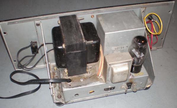 |
| Not much remains
that hasn't been replaced on this WE11. The two (slightly oversize)
transformers are replacements, with only the filter choke being original.
The wires and line cord have also been replaced since they were deteriorated
and unsafe. A fuse holder, very evident here, was added to the front
panel by a previous owner. This picture does however, illustrate
the general construction of the WE11. (Photo by Jason Ingraham
VE1PYE) |
 |
| Underside view of
the WE11 chassis. Not all the parts are original. (Photo by Jason
Ingraham VE1PYE) |
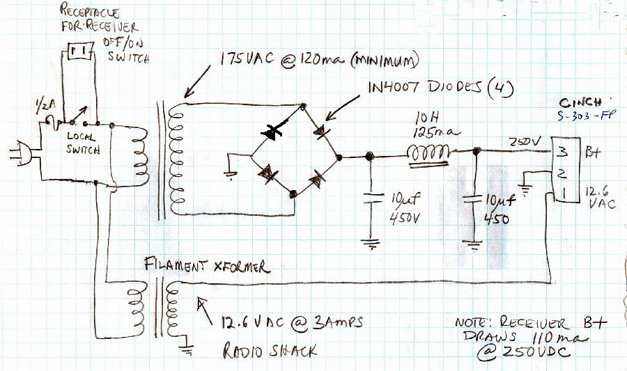
For anyone
wishing to construct their own CSR-5 power supply here are the receiver's
requirements:
B+ 250 VDC at 110
ma; Filaments 12.5 VAC or VDC at 3 amps. Suggested schematic available
at the bottom of this document.
 |
 |
| This
is the common power connector housing for a cabinet-mounted CSR5A. Receivers
in standalone cabinets can also use the connector housing shown in the
rightmost photo. (Photo by Jim Brewer) |
Power
connector housing for CSR5A fitted into a CM11. Receivers used in CM11
cabinets can also have the connector housing shown in the leftmost photo.
(Photo
by Jerry Proc) |
LOUDSPEAKERS
Standalone
Speaker #110-823
This is an 8 inch
permanent magnet speaker mounted in a case 12' wide x 12 wide x 6 in deep.
A two screw terminal strip is provided for the connection to the receiver.
 |
 |
| Front
view of #110-823 speaker with original gray crackle paint. It comes with
mounting brackets for attachment to a ship's bulkhead. (Photo by Meir
Ben-Dror,
WF2U) |
Rear
view of another #110-823 speaker showing the high impedance transformer
and original, green hammertone paint peeking around the back perimeter.
(Photo
by Meir Ben-Dror, WF2U) |
 |
 |
| This #110-823 speaker
is painted in black crackle. It is 10 wide, 9 high and 7 deep.
Speaker hole is 7 in diameter. (Photo by Jason Ingraham VE1PYE) |
This
variant of the speaker uses a black grille screen and bezel with a light
grey finish on the cabinet. |
 |
 |
| This
#110-823 speaker is fitted with a screen instead of cloth behind the grille.
(Photo
by Greg Farrell) |
Rear
view. Speaker p/n is 116-260 Transformer bears p/n 4D126G72 (Photo
by Greg Farrell) |
 |
|
| Another variation
in the grille material |
|
Rackmount
Speaker #110-836
The panel is 19 inches
wide by 10.75 inches high
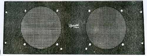 |
| #110-836
speaker panel .The manual does not say whether these are two speakers wired
in parallel or whether they are two independent speakers. (Image courtesy
Canadian Marconi) |
CRYSTALS
RECEIVE CRYSTALS
For operation using
crystal control, the crystal must be 575 KHz higher than the desired receiving
frequency when the crystal is operating on its fundamental frequency. RCN
operators also hand marked CSR-5 crystals with the frequencies of the second
harmonic and the third harmonic. The receiver could be tuned to operate
on the fundamental or the second or third harmonic. The following
standard
RCN crystal frequencies were available for the CSR5 receiver.
 |
| The
CSR5 or CSR5A can accept a type 'BY' crystal which is depicted on
the right, while the CSR5A (only) can accept either of the
crystals depicted in this photo. The case style of the leftmost crystal
is not known at this time, however its dimensions are 1.125 in wide
by 1.25 in deep by 3/8 in high. The pins are on 1/2 inch centres.
(Photo
by Jerry Proc) |
FILTER CRYSTAL
During an alignment
on the IF stage, one troubleshooter noticed that the top iron core of T1
in the IF crystal filter was quite broad and had no noticeable peak anywhere
in its travel. On removing the
filter module, he
noticed a "clunk" as it was moved around. This was traced to the 575 KHz
filter crystal. Opening the crystal and fearing the worst, he discovered
the center element of the crystal was free to slide around in the
holder and was only guided by supports on either side. This turns out to
be normal since the crystal in the filter circuit is of the "loose resonator"
construction (exact name is unknown) versus the "fixed" type whose
quartz element is fixed between two, spring loaded, metal electrodes. Loose
resonator crystals work on the principle of a quartz element operating
in a small air gap and free to slide back and forth, however the exact
principle is not known at this time. In this instance, the disassembly
and reassembly of the crystal cleared the problem. So why did Canadian
Marconi choose to use a loose resonator crystal (575 kHz) for the filter
circuit and fixed resonator crystals for fixed frequency operation of the
receiver?
 |
| Exposed: The two
pieces which constitute the guides are ground glass and are slightly thicker
than the resonator. The resonator element is allowed to move freely within
a .003 inch air gap and from side to side. (Photo by Jason Ingraham
VE1PYE) |
 |
| This 575 kHz filter
crystal, with identical Canadian Marconi identification to the one above,
was pulled from another CSR-5. With its three glass support elements, why
does this one differ? (Photo by Jim Brewer) |
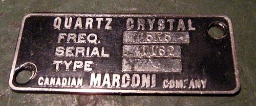 |
| 575
KHz crystal nameplate. (Photo by Jim Brewer) |
In the September
1934 edition of QST magazine, James Millen, President of the National Radio
Company explained these "loose resonator" crystals. Here are key extracts
from that article.
"Perhaps
the greatest misunderstanding centres around the resonator crystal and
its holder. It is surprising how how many amateurs do not realize that
the resonator crystal must NOT be under pressure. For resonator crystals,
we have found that an air gap of approximately .003 inches to be essential.
In order to properly maintain this air gap, we have found it most practical
to separate the holder plates by means of two carefully ground glass parallel
bars or spacers. The crystal element itself is placed between the spacers.
From our correspondence many amateurs believe we are using three "trick"
crystals apparently concluding that the spacer bars are made from quartz.
In an earlier model
of resonator crystal, we used a bakelite spacer ring surrounding the crystal.
This ring was carefully ground so as to provide the .003 inch air gap between
the crystal proper and the plates. It was startling as to how many amateur
complained to us that upon opening their crystal holder they were surprised
to find that we had been careless in using a spacer that was thicker than
the crystal and consequently prevented the holder plates from touching
the crystal. They were filing down the bakelite spacer ring until it was
thinner than the crystal.
Then there is the
matter of polarity of the crystal holder. When using a holder with horizontal
plates, it is important that the holder be inserted in its socket the same
way at all times otherwise it will be necessary to rebalance the bridge
circuit".
 |
| Crystal
filter compartment with cover off. (Photo by Jerry Proc) |
MAINTAINING THE CSR-5
CASE and FRONT
PANEL COLOURS
CSR5 receivers came
in five known paint schemes. When standalone, in their own cabinet, the
paint finish was of the crackle type. When part of the CM11, the finish
was typically glossy, light gray.
1) When the
CSR5 was part of a CM11, it had white lettering over top the light gray,
smooth paint.
 |
| This
CSR5 is part of the CM11 in Radio 2 aboard HMCS HAIDA. (Photo by Jerry
Proc) |
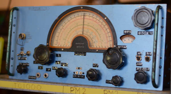
2)
This pale green was a very common finish for the CSR5. An exact paint match
was made from the CIL Paint line in 1993. It's called Silver Lace #10GY49/081-7
but its availability is unconfirmed in 2007. Note the transparent
type decal front panel markings, It is suspected that these were applied
after the receiver left the factory, perhaps as a result of repainting
the front panel. In cases such as this, the dial bezel will
lack the stylized "Marconi Canada" script.
 |
| This CSR5 S/N 122
is from the collection of Richard Brisson. (Photo by Richard Brisson) |
3) Light
gray crackle paint with black, silk screen lettering as below .
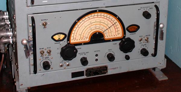
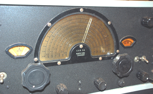
 |
| This
example was painted with a beige/grey hammertone finish. Note the
"dual semicircles" for each band marking on the dial. (Photo by
Jerry Proc) |
4) Medium
blue-gray with white lettering.
 |
| This
example, painted dark blue, is found aboard HMCS HAIDA. (Photo
by Jerry Proc) |
5) Black
crackle with white, silk-screen lettering as in the case of this CSR-5
 |
| This
CSR5 S/N 219 belongs to Jason Ingraham. (Photo by Jason Ingraham
VE1PYE) |
6) Black
crackle with white, silk-screen lettering as in the case of this CSR-5Y.
 |
| This CSR-5Y example
is owned by Meir Ben Dror. (Photo
by Meir Ben-Dror, WF2U) |
 |
| This CSR-5A, S/N
103, is painted in black "alligator skin" finish with stencilled lettering
on the front panel. Click on image to enlarge. (image via Tom <pearsrepairs@hotmail.com> |
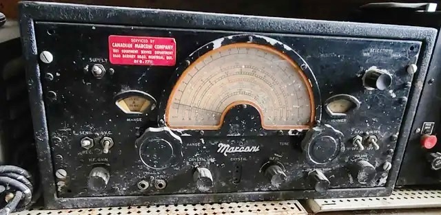 |
| This CSR5A has a
red label stating that it was serviced by Canadian Marconi, Only
two examples of this have been observed thus far. Note the Marconi name
in raised, chromed lettering just below the half moon dial. (E-bay
photo) |
 |
| S/N 103 has been
fitted with this raised ,chrome logo, positioned horizontally.
(Photo
by Greg Farrell). |
7) Here
are two examples of restoration no-nos. This is how a CSR5 should never
be refinished - aluminum paint with Dymo tape lettering.
 |
| Many decades ago
it was believed that the supply of surplus gear would last forever, so
modifications like these were typical of the period. Oddly enough the small,
black engraved plate indicates Serial number 1 but that has to be taken
with some doubt since the three pin crystal socket suggests that it's a
CSR-5A. It also looks like the front panel lettering composed of name tags
which have been removed and replaced with DymoTtape labels. (Photo
source unknown) |
 |
| This example also
illustrates an improperly restored CSR5 receiver. Work such as this significantly
reduces the value of the artifact and makes it undesirable to serious collectors. |
 |
| In the lower photo
someone has added an inboard power supply to the cabinet lid. The new owner
will be stripping out these components and constructing an outboard supply.
(Photo
by Carl Nord WA1KPD) |
 |
| This
CSR-5 has been modified .however the purpose of the mod is not known at
this time. A Speaker In/Out switch replaces the Crystal In/Out switch.
The crystal socket is replaced with an a miniature Tape Out jack and the
holes that were visible were filled with some compound material . It was
done very professionally. Below the bezel, the receiver is shown
to be a CSR-5A but that is incorrect. It should be a CSR-5 as suggested
by the position of the selectivity control and power off/on switch. Except
for the bandswitch and tuning knobs, the knobs are not genuine Marconi.
The receiver, formerly owned by radio operator John Gilbert, was donated
to the RCS Museum in Kingston , Ontario. Click on photo to enlarge.
(
Photo by John Gilbert) |
8) Was This
a Pre Prototype Receiver?
 |
| This might be a
pre-protype CSR5 receiver. The bands on the dial are monochrome; the crystal
socket and crystal in/out switch are not there and it appears a meter was
added by perhaps someone who owned the receiver after it became a surplus
item. The cabinet paint is kind of a dark green bordering on black. This
example is held by the C&E Museum in Kingston. (Photo by Jerry Proc) |
CASE
VENTILATION
The CSR5 cases were
manufactured in to variations.
CSR-5 cabinets have
2 ventilation screens on the lid, 2 ventilation screens in the back and
1 ventilation screen on each side.
CSR-5A cabinets have
2 ventilation screens in the back and 4 ventilation screens on each side
(none in the lid).
CSR-5 cabinets have
a rectangular hole at the lower right-rear for the power connections. Both
connections are oriented perpendicular to the back wall of the chassis.
In other words, they go straight out the back from the little box they
are mounted on.
CSR-5A cabinets have
an irregularly shaped hole for the power connection because the cables
connect to the top and side of the small box mounted on the rear of the
chassis. CSR-5A cabinets also have 2 steel pins mounted on the inside of
the back wall of the cabinet that mate with holes on the left and right
side
of the back wall of the receiver chassis.
A CSR-5 receiver
will not mount in a CSR-5A cabinet unless the pins are removed.
Conversely, a CSR-5A
receiver will not fit in a CSR-5 cabinet unless the rectangular hole is
cut out to allow the Cinch-Jones type power connectors to pass through
the back wall of the cabinet.
The final difference
between the two cabinets is that CSR-5 cabinets have one finger pull and
CSR-5A cabinets have 2.
NEW HALF-MOON
DIALS
Meir Ben-Dror, WF2U
had a badly chipped half-moon dial which he repaired. Here was a
summary of the process he used to make a new one. "First I made a high
resolution scan of the dial. The paint was missing in a few little
sections in the grooves of the orange and green band/frequency markings
so I used Photoshop to touch up the markings I printed out the dial on
heavy, semi-gloss photo paper, and coated it with Krylon protective spray.
The reproduced dial looks indistinguishable from the original. It even
looks 3 dimensional due to the high resolution scan and some enhancements
I did with Photoshop. Then I matched some acrylic artist's paint and touched
up the markings on the original dial then wiped off the excess from the
surface. It is not known at this time if the heat from the dial lamps will
have any adverse effect on the new dial indicator".
Dials came in two
styles. One style had the single half moon markings for each band while
the other style had the double half moon markings which resemble a railroad
track. These differences are shown in the two photos below.
 |
| This dial, from
a CM11 mounted CSR5 s/n 392, was in a deteriorated state. The dial pointer
is held on with a single Bristol screw and is easily removed. Note that
the colours of A and B bands are reversed to that of the dial which was
scanned from a CSR5A. (Photo by Meir Ben-Dror, WF2U) |
 |
| This is the finished
reproduction '5A' dial with pointer reinstalled. (Photo by Meir Ben-Dror,
WF2U) |
 |
| The
final product - a professional looking dial .(Photo by Meir Ben-Dror,
WF2U) |
 |
| Ever
wonder how a CSR5 dial looks with the silk screening removed? Here is an
example. (Photo by Jerry Proc) |
CHASSIS
In the CSR 5A, the
band-switch assembly has been wired into a sub-chassis which can be detached
from the main chassis. This operation should be never be attempted by the
inexperienced. First, you extract the receiver from its case and detach
the bottom cover plates - do not be concerned over the 30 screws that secure
the plates. Next, desolder 29 connections as outlined in the manual. Following
that, there are another 20 screws to remove in order to physically detach
the RF bandswitch assemply. Do not go insane in the process, or you won't
be able to get the pieces back together. This brief glimpse of 1942 radio
maintenance has been presented for those who have complaints about current
manufacturing methodology!
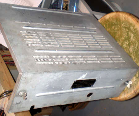 |
| When a CSR5 was
intended for rack mounting, it was provisioned with a protective
cover such as this. This is the cover for S/N 219. Note the louvers with
screen backing and the other differences in the cutouts when compared to
the example below. (Photo by Jason Ingraham VE1PYE) |
 |
| This cover from
S/N 103 only has one large opening for ventilation which covered with a
perforated screen. (Photo by Greg Farrell). |
 |
| The dust cover attaches
to female Dzuz latches which are mounted on the the chassis sides at the
back. (Photo by Jason Ingraham VE1PYE) |
 |
| S/N 103 has its
serial number stamped in ink above the audio jacks but no nameplate. (E-bay
photo) |
There may
be an easy explanation for the rubber stamped serial number. This may be
an early, "bid sample" or a prototype for the production line. Until a
firm order was received, it would not make financial sense to provide
the tooling to produce a metal nameplate. That would come after a firm
order was received. Perhaps Marconi simply did not have all the parts at
hand as production started.
CSR-5 DOCUMENTS
The following
CSR5 technical information is available for download. The CSR5A schematic
was redrawn by Denis Chouinard VE2DSH. David Noon provided the CSR5 erratum.
In 1959 the RCN developed a test agenda for the CSR5 which has also been
included.
PRODUCTION
SUMMARY
Based on the few
snippets of information which have been located so far, a tentative time
line for the CSR-5 is beginning to emerge.
* We know that
production of CSR-5 receivers in a stand-alone cabinet (Type 110930-Z)
did not begin until late 1943, possibly early 1944. Further, we know that
the switch from CSR-5 production to the CSR-5A model probably occurred
in July or August 1944. A photo from this time frame confirms
that the CSR-5 was being installed aboard new ships and the SMR-3 was no
longer standard receiving equipment.
* September 1942:
CSR-5 receivers in production as Type 110 480 installed in CM-11 transmitter
receivers. (Evidence from notation in CM-11 manual, production likely started
earlier)
* ???? 1943: Rack
mount CSR-5 receivers (Type 110835W) in production. (Evidenced by WE-11
ID plate patent date of 1927-43.)
* March - August
1943: RCN places orders for 740 receivers, New Zealand places orders for
100. Presumably, these orders are for Type 110-930 (stand-alone receiver
in cabinet).
* July 1943: Expected
date for production to begin.
* August 1943: Production
had not commenced; production now forecast to start December 1943 .
* September 1944:
Serial #816 is the last of the stand-alone receiver production.. At this
rate of production, it would suggest that all of the CSR-5/5A's found
so far, up to the highest serial number of 1025, were built before the
cessation of hostilities in 1945. ( Serial number 816 was stated in Naval
Service Order 1008-78-1 dated Sept 2, 1944)
POTPOURRI
 |
| Is this the production
line at Canadian Marconi circa 1944? No...its Meir Ben-Dror's workbench
where a group of CSR-5 receivers are being restored back to their former
glory. (Photo
by Meir Ben-Dror, WF2U) |
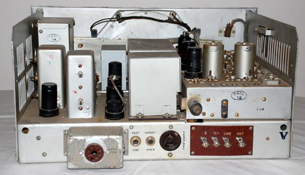
 |
| This is the workbench
of Jason Ingraham VE1PYE. CSR5 S/N 219 is undergoing troubleshooting. Behind
it is the WE11 power supply and the Marconi speaker. (Photo by Jason
Ingraham) |
 |
| September
2007: Radio 1, starboard view aboard HMCS HAIDA in Hamilton , Ontario.
All these receivers were brought back to working order by Jerry Proc. (Photo
by Jerry Proc) |
Contributions and
Credits:
1) http://www.qsl.net/ve3bdb/signalshistory4.htm
by Bob Cooke VE3BDB
2) Meir Ben-Dror,
WF2U <wf2u(at)ws19ops.com>
3) Tom Brent <navyradiocom@gmail.com>
4) Denis Chouinard
<denischouinard(at)enter-net.com>
5) Richard Brisson's
Boatanchor web page: http://home.ca.inter.net/~hagelin/boatanchors.html
6) CSR5A Manual
#110-434A
7) Jim Brewer <snack.235@sympatico.ca>
8) Jason Ingraham
<the_doctor31(at)hotmail.com>
9) Greg Farrell,
Santa Rosa, California <gregf(at)pon.net>
10) Carl Nord WA1KPD
<chnord(at)comcast.net>
11) David Noon
<va3dn(at)execulink.com>
12) Gary I. Biasini
<gary.biasini(at)shaw.ca>
13) Rob Moffatt
<rmoffatt3(at)gmail.com>
14) History - Signals
Production Branch , Department of Munitions and Supply, October 15, 1943
15) Gerry O'Hara
[gerrycohara@gmail.com]
Back
to Equipment Listing
Aug 20/25


