FR-12 Transmitter-Receiver
The Canadian Marconi
FR-12 transmitter-receiver was, as explained in the operating manual, "designed
for operation on marine frequencies on small ships, notably fishing vessels".
That might have been Marconi's intended market but after the outbreak of
World War II in 1939 ,it appears to have been adopted by the Royal Canadian
Navy as standard equipment for the large numbers of new vessels soon to
be coming out of the builder's yards. It fulfilled the communications role
for small coastal patrol vessels and supplemented more powerful long-range
equipment installed on ocean-going ships
During WWII, the
FR-12 was a mainstay on many RCN vessels and was used on CW for inter-communication
between escort ships on convoy runs. Voice was available but rarely used.
The popularity of the FR-12 dropped when the TBS transmitter/receiver was
introduced into service. On low wave band, the set had a range of
about 20 miles.
In a peacetime navy,
the FR-12 was used to communicate with merchant ships or the Naval Administrative
Net (at sea). Pictures taken in the 1950's show the handset installed,
so it was definitely used on voice. Emergency communications could be provided
by the FR-12 since it only operated from a 12 volt DC power source. The
receiver section consisted of a five tube superheterodyne design with the
ability to continuously tune the range of 375 to 4200 KHz in three bands.
To simplify the overall design, there was no direct frequency readout for
the receiver. Instead, a circular logging scale dial was provided. It was
necessary to calibrate the dial, and record the readings in advance.
The transmitter section
had an oscillator, a modulator and a dual power output stage. One of four,
selectable, internally mounted crystals determined the operating frequency.
In order to activate the modulator, one simply inserted the handset plug
into the front panel socket. The microphone in the handset provided the
interlock for the modulator. If this was done while the Dynamotor was running,
a noticeable slow down of the Dynamotor could be heard.
Power for
the FR-12 could be provided by one of two modes. In standby mode, the filament
circuit for the transmitting tubes gets disabled. Filament power for the
receiver would be provided from the main battery. The 180 volt B+ line
for the receiver would be furnished from four, external, 45 volt dry batteries
wired in series. Standby mode would dramatically increase the life of the
main battery. In normal mode, all power for the receiver and transmitter
was provided by the main battery. An internal Dynamotor produced high tension
for the transmitter but it had to be inspected after every 500 hours of
operation. Al Goodwin of Dartmouth N.S. did some range experiments with
the FR-12. "It was sent away in a sea boat on a couple of occasions. In
those days, we didn't have commercial mobile antennas available to us,
so we rigged up a 35 foot whip antenna. The exercise was not deemed a success
as we lost communications around five miles. On HMCS HAIDA, we used this
set for both AM and CW communications. For CW operation, we would have
to attach a key with a very long lead. In an unusual case, the late Keith
Lake (VE1PX) used the FR-12 to modulate the Marconi PV500 transmitter thus
giving it AM capability for use on the amateur bands. He put out quite
a strong signal compared to the 30 watts of the Marconi CM11".
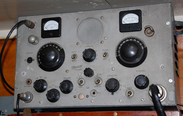 |
| Normally the FR-12
would have a feedthrough insulator in the upper left hand corner. The RCN
modified these sets by replacing the feedthrough with an SO-239 receptacle
so the antenna could be fed with a co-axial transmission line instead of
antenna trunking. This example is fitted in HMCS HAIDA. (Photo
by Jerry Proc) |
SPECIFICATIONS:
Types: FR-12 (12
volt) #85161-T
FR-12 (32 volt) #85135-T
Modes: CW, MCW and
Voice
Frequency Coverage:
LF/MF - 375 to 580 KHz (transmit)
HF -1580 to 4200 KHz
(transmit)
MF Receive only - 550 to 1600 KHz
MCW oscillator
1,000 Hz
Power Input: 15
watts on CW, less on MCW and even less on voice.
Power draw:
12 volts DC at 6 amps on receive and 13 amps on transmit. There are variants
which use 32 VDC for input power.
Frequency Control:
Four crystal controlled frequencies.
Receiver IF: 260
KHz
Weight: 69 lbs.
Duty cycle: 5 minutes
transmit followed by 5 minutes receive, otherwise the Dynamotor will overheat.
CIrca: February
1942 as dated in the manual.
RCN Ref. Number:
5820-21-041-1615
The following
standard crystal frequencies were available for the FR12:
391.5 KHz -
Usage ?
425 KHz - Port wave
500 KHz -
Distress
1630 KHz -
Unique Canadian west coast maritime mobile working frequency..
Crystal case style
is ' BY'
POWER CABLE
If your FR-12 does
not come with a power cable, that is problematic since the male and female
connectors are no longer available as new stock. The front panel power
connector CC1 is an Amphenol 92C1. The mating female connector on
the power cable is an Amphenol PC-4M.
In this situation,
it will be necessary to remove the front panel power connector and replace
it with an suitable substitute. If the replacement connector has a flange
mount, some front panel drilling will be necessary.
Make sure that the
pins for the 12 VDC line can handle 13 amps if there is any intention
to transmit with the FR-12. Otherwise if the intention is only to receive,
two power sources need to be available: 12 VDC at 6 amps and 180 volts
at 50 ma (est).
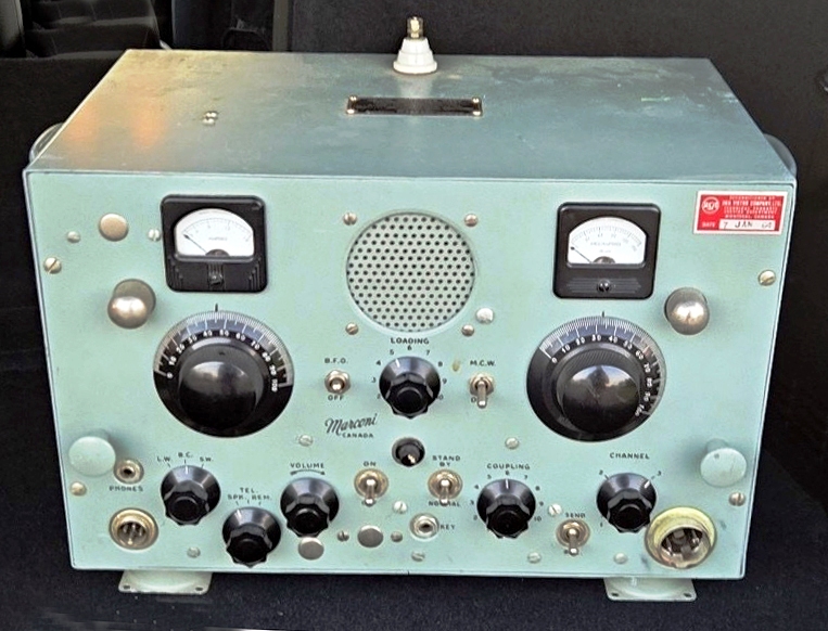
 |
| Above and below:
This pristine and unmodified example of the FR-12 is owned by Meir Ben-Dror
WF2U. Note the RF feedthrough insulator with wing nut to the left of the
meter. (Photos by Meir Ben-Dror) |
 |
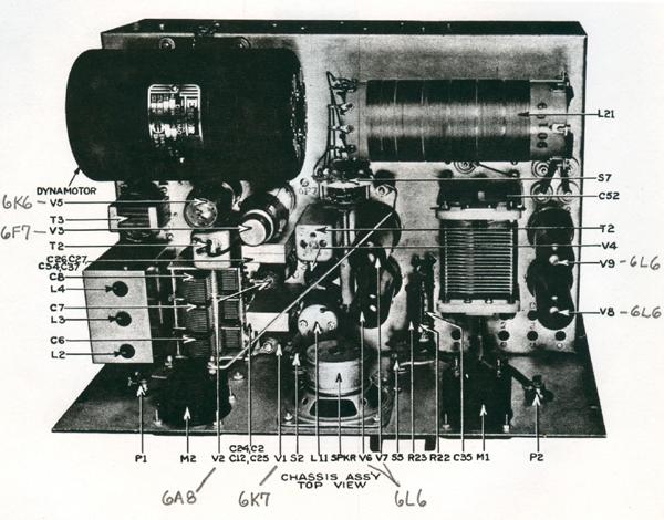 |
| FR-12
- top view of chassis. (Image courtesy Canadian Marconi) |
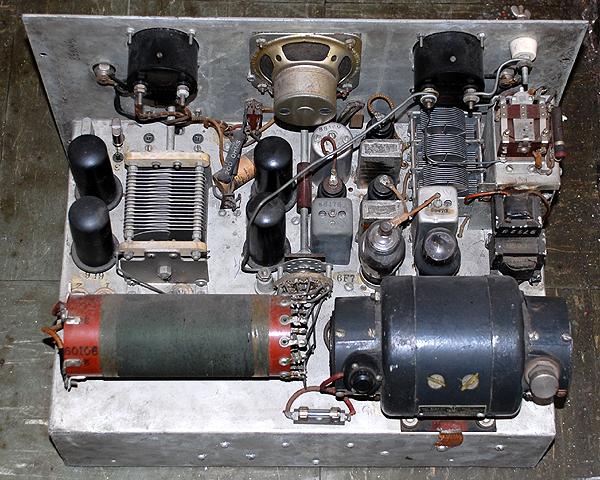 |
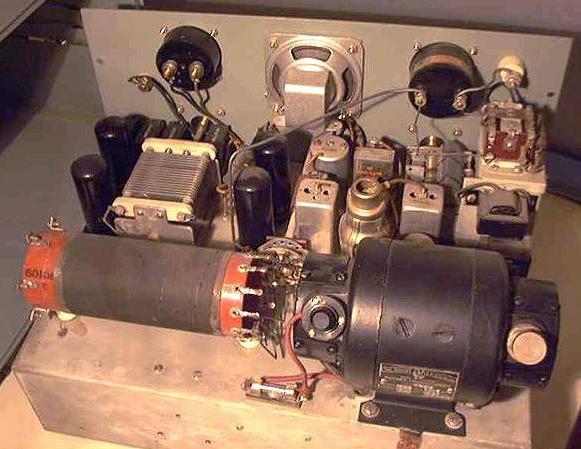
| Another
example of the FR-12 chassis top view. (Photo by Jerry Proc) |
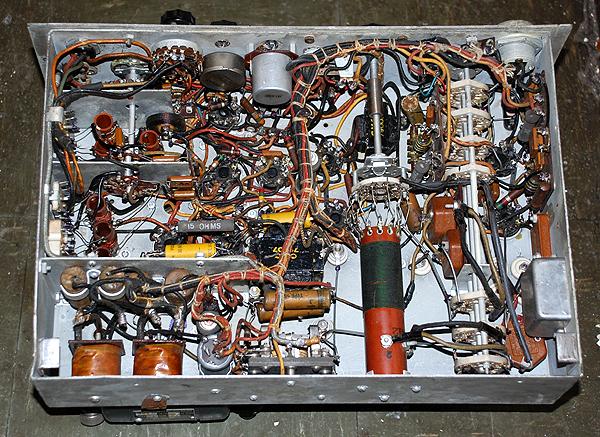 |
| FR-12
- bottom view of chassis. (Photo by Jerry Proc) |
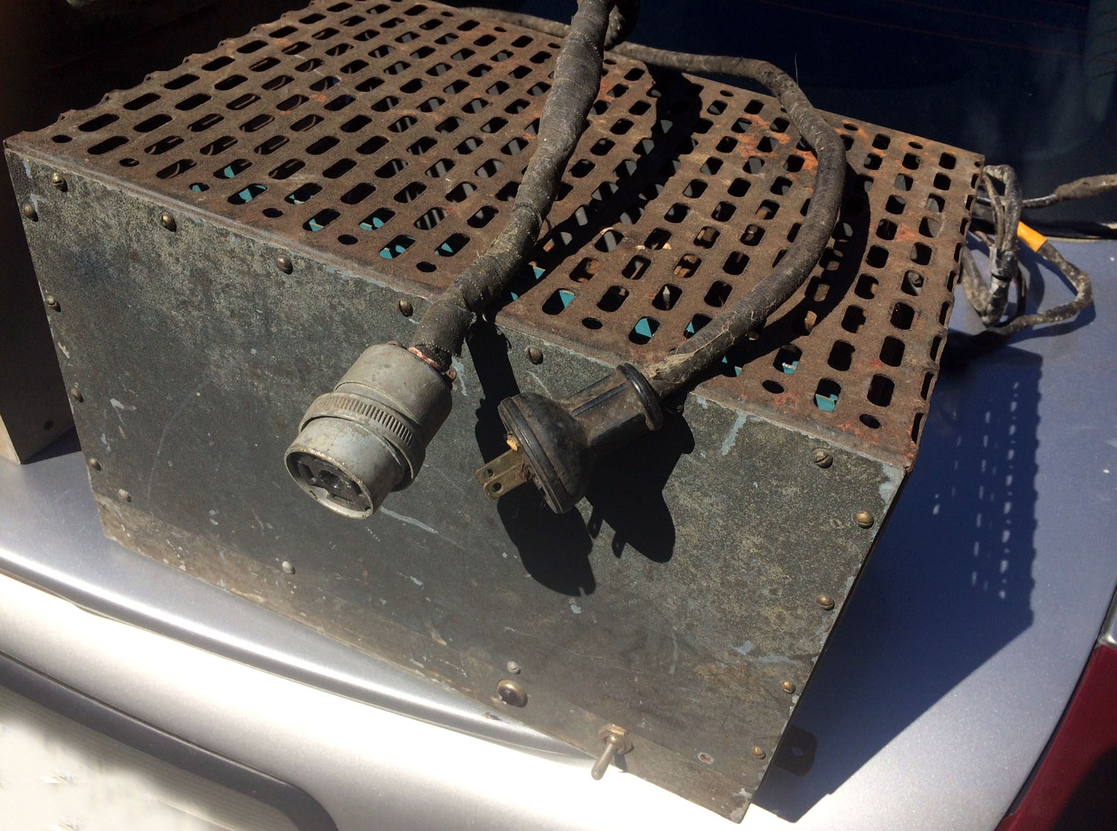 |
| This
is the AC operated power supply for the FR12. It came in either a 12 or
32 volt version. The FR12 could also be operated from an emergency battery
source. (Photo by Alastair Slydell , VA7COB) |
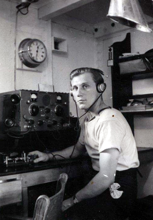 |
| Radioman
H. Cook might be sending Morse from the the FR12 in this undated photo.
Note the cradle arrangement for the FR12 handset. He is also
using a semi-automatic key (bug( which was not standard RCN issue. Any
operator wishing to use a bug would have to provide their own.. If Canadian
Marconi was purchasing keys from Signal Electric for the CM-11, it seems
reasonable they would go to the same manufacturer for their FR-12. Also,
a number of firms made clones of the Signal Electric key, including SpeedX.
(Photo
credit unknown) |
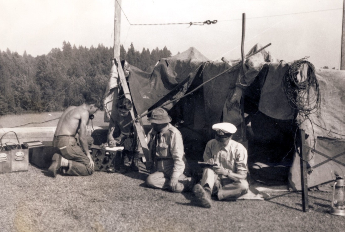 |
| The
FR12 being used during the Fraser Valley floods of June 1948. Click on
photo to enlarge. (Photo submitted by Tom Brent) |
VARIANTS
There were
lots of FR12 variants based on mains voltage and crystal combinations.
The following mix of LF/MF and HF channels could be ordered from
Canadian Marconi:
85161 FR-12
(12 volt)
85135 FR-12
(32 volt)
85135S
(32V) Channels 1 and 2 for LF/MF; Channels 3 and 4 for HF
85161S
(12V) Channels 1 and 2 for LF/MF; Channels 3 and 4 for HF
85135AS (32V)
Channels 1, 2, and 3 for LF/MF; Channel 4 for HF
85161AS (12V)
Channels 1, 2, and 3 for LF/MF; Channel 4 for HF
85135BS (32V)
Channel 1 for LF/MF; Channels 2, 3, and 4 for HF.
85161BS (12V)
Channel 1 for LF/MF; Channels 2, 3, and 4 for HF.
A -H in the
model number indicates that the remote control option was installed. The
manual does not do a good job in explaining the variants. In the back of
the manual there is a hand written note indicating PH , TH and BRA variants.
PH = FR-12P with
remote control option, 2LF and 2 HF crystal positions
TH = FR-12T with
remote control option, 2 LF and 2 HF crystal positions
BRA = FR-12R,
1 LF and 3 HF crystal positions (meaning of "A" unknown.( Maybe its
an error)
Besides
power supply and crystal variants, there are three different methods
of feeding the RF from the output stage to the transmission
line. This is another area that is poorly documented in the manual. Early
units had the RF feedthrough mounted atop the cabinet . This design
required a spring contact mechanism that completed the circuit from the
RF ammeter output terminal to the antenna insulator when the FR-12 chassis
was inserted into the case. FR-12s from 1944 onwards had the antenna insulator
mounted in the top left corner of the front panel, only an inch or two
away from the RF ammeter terminal it needed to connect with. This resulted
in a simpler design, possibly eliminating problems associated with the
spring contact mechanism. However, there are three historical photos which
show the antenna insulator installed to the right of the RF ammeter.
From the manual
"The antenna should be connected to the insulator projecting through the
top of the cabinet .The chassis will then slide out, with the antenna connection
to the chassis being made by a spring contact which breaks automatically
when the unit is withdrawn". No such example has been seen thus far.
Some existing photos show no feedthrough insulator on the front
panel or the top of the cabinet. It is then presumed that the RF exits
the cabinet by some other method which has yet to be discovered.
The nodel
CD-12 was the Canaduan Army version of the FR12. It had a sping loaded
binding post for RF output and it was situated to the left
of the RF ammeter.
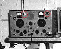 |
Note
the position of the feed through insulator in this example. The insulator
is to the right of the RF ammeter.
In the upper right
cormer, it is susprcted that this component is a round-case crystal.
. This FR12 was fitted in the vessel RCMP Irvine in 1950. |
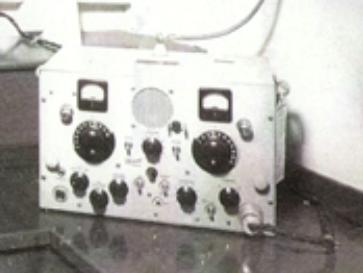 |
FR-12
in Fairmile Q112. (Photo via James Taylor)
This FR-12 was fitted
in Fairmile Q112 while still at the builder's yard. This example appears
to have the RF output feedthrough insulator on top of
the cabinet. |
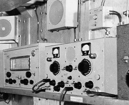 |
| This FR12 was fitted
in the radio room of HMCS Rupert in 1942. Note the absence of any front
panel feedthrough insulator for the RF output. . (Public Archives Canada
Photo HS-0262-1 submitted by Spud Roscoe) |
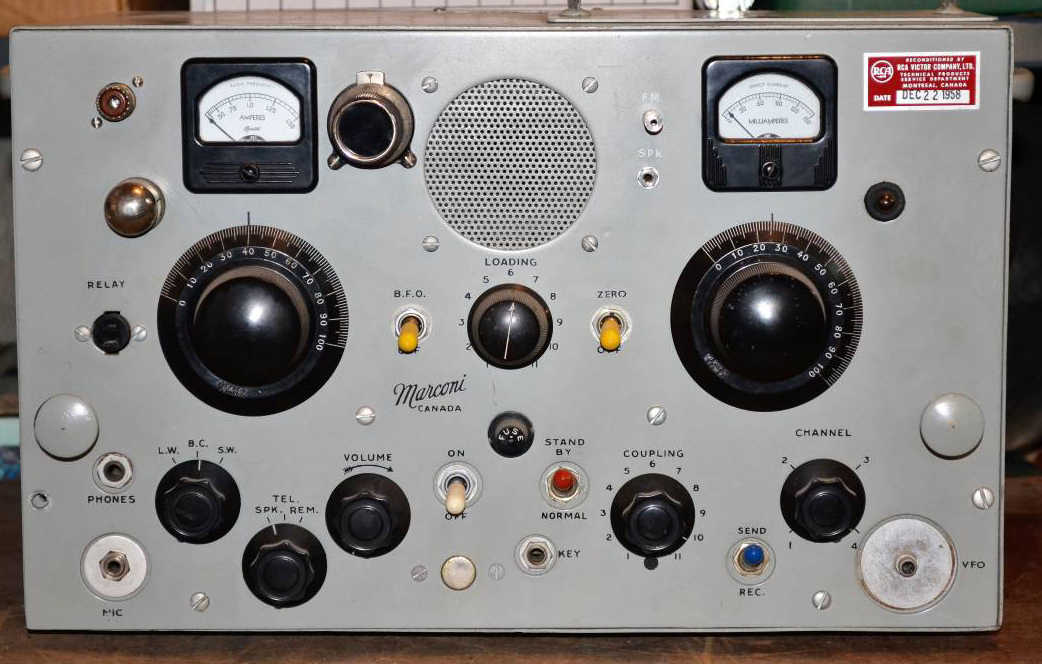 |
| This FR12 was reconditioned
by RCA on December 22, 1958. After the FR12 left RCN service, it received
some modifications by one of its previous owners. FR-12's were still being
reconditioned as late as October 1963 as evidenced by the tag on FR-12
S/N 128 owned by Meir Ben-Dror. (Photo via Kijji) |
 |
| Painted in a light
powder green, this variant had the RF feedthrough insulator mounted atop
the case instead of the front panel. ( Photo provided by Jason Ingraham) |
CRYSTAL
ACCESS
The new and improved
FR-12 of 1944 had another feature as shown in the photos below:The crystal
access door eliminated the need to remove the chassis from the cabinet
although, from the left-hand photo, it appears that lining up and installing
a new crystal would be difficult. Some of the 1942 production
models had a crystal socket mounted on the front panel which would have
some advantages over changing crystals through the top mounted access door
 |
 |
| With
access cover removed, (Photo by Tom Brent) |
With
access cover in place. (Photo by Tom Brent) |
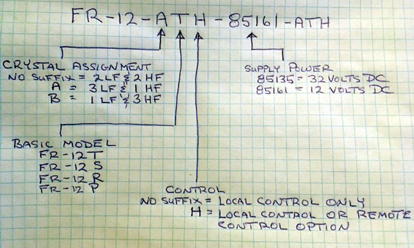 |
| This
chart, provided by Tom Brent, sums up the FR12 variants nicely. |
SUMMARY
From the
few study examples that are available and the pool of existing photos,
radio collector Tom Brent was able to make the following conclusions:
1. It is likely that
all FR-12's were originally painted with a wrinkle finish, any existing
examples with flat (semi-gloss) finish were repainted as a part of the
reconditioning process many sets underwent in the late 1950's and early
1960's. Originally, wrinkle paint was also applied to the outside of the
case and the front wall of the chassis. The interior of the cabinet
was the same colour as the front panel and exterior of the case but was
a flat (non-wrinkle) finish.
2. Early FR-12's
had the antenna insulator mounted on top of the cabinet and this was connected
to the RF ammeter by a spring contact mechanism attached to the ceiling
of the cabinet.
3. Many early FR-12's
had the antenna connection modified by relocating the antenna insulator
to the front panel, on the right-hand side of the RF ammeter. It cannot
be determined if this modification was carried out by Canadian Marconi
or if it was completed "in the field" by RCN personnel.
4. Some of the early
FR-12's were factory supplied with a crystal socket for Channel 4 mounted
on the front panel and an additional switch which enabled the filaments
of the transmitter tubes to be supplied with power when the set was in
standby mode (receiver only operation from external B+ battery supply).
5. In 1944, FR-12's
were being supplied from the factory with the antenna insulator installed
on the left-hand side of the RF ammeter and a crystal access door in the
top of the cabinet, secured with two Dzus butterfly catches.
6. Also in 1944,
sets were equipped with an additional relay connected to a Jones socket
mounted on the front panel. This relay was likely factory installed but
its purpose is unknown at this time.
7. Later sets also
have an unknown control located to the left of the key socket and accessed
by removing a plug. This may be a switch with a purpose similar to the
one mentioned in point 4 above although this still needs to be confirmed.
So what we have now
in the way of FR12 variants :
- Operation on two
different mains voltage.
- Four different
MF/HF crystal configurations on the chassis.
- One crystal socket
on the front panel for quick change of frequency.
- Three different
positions for the RF feedthrough insulator.
- Offset lettering
for the remote control socket.
- With and without
crystal access plate atop the cabinet ,
 |
| This FR12 example
is owned by Tom Brent and refurbished by Gerry O'hara. It serves to illustrate
the front panel crystal socket and the RF feedthrough insulator to the
right of the RF ammeter just like the example aboard RCMP Irvine. The RED
and CLEAR indicator lamps are not original to the FR12. The
original lamps were intended to illuminate the two large black knobs. Click
on image to enlarge. (Photo by Gerry O'hara) |
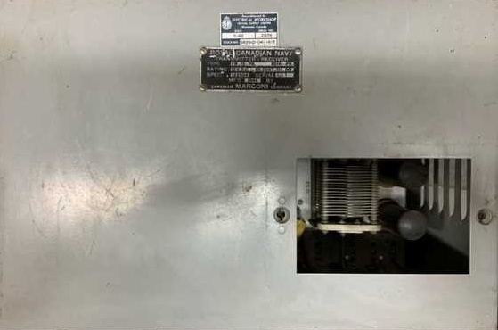
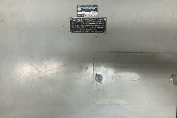
SERIAL NUMBERS
Because
there are so few surviving examples of the FR12, it is difficult to collect
serial numbers. Here is what we have so far:
Type FR-12-TH
Spec. 103-851 Serial 310 Manufactured 1942 (Owner:Tom
Brent)
Type FR-12-PH
Spec. 122904 Serial 581 Manufactured 1944 ( Owner:
SPARC Museum)
Type FR-12-PH
Spec ?
Serial 582 on case: Serial 398 on chassis (HMCS HAIDA).
Type FR12-P
Spec 107-803 Serial 128 (Meir WF2U)
DOCUMENTATION
The following
FR12 documentation is available for download:
ERRATA
The nameplate
on the dynamotor made by Robbins & Myers indicates an output voltage
of 350 VDC at 225 ma.
The following standard
RCN
crystal frequencies
were available for the FR12 transmitter/receiver.(High
frequency)
The following standard
RCN
crystal frequencies were available for the FR12 transmitter/receiver.(Low
frequency)
Contributors and
Credits:
1) Meir Ben-Dror,
WF2U <wf2u(at)ws19ops.com>
2) Marc-André
Morin <marc-andre.morin(at)videotron.ca>
3) Tom Brent <navyradiocom(at)gmail.com>
4) Alastair,
VA7COB <lothlorian(at)shaw.ca>
Back
to Equipment Listing
Oct 22/24