Marconiphone III
(M3) Receiver
SPECIFICATIONS
Model: Marconiphone
M3
Type: TRF (Neutrodyne)
Made by: The Marconi
Wireless Telegraph Co. of Canada, Montreal.
Frequency Range:
Broadcast band
Tube lineup:
Five UV-201A
Circa: First production
1924
Original price:
$300 .
Comment: The Marconiphone
III was a completely original development of the Marconi Wireless Telegraph
Co. of Canada.
M
III schemetic here.
INTRODUCTION
In
the 1920s, when the Canadian Department of the Interior held a literary
contest for all of Canada called Forests Protection it was supported
by the most important Canadian newspapers of the time. The prize was to
be a high quality radio receiver. Not wanting to award just any receiver,
the existing receivers of the time were evaluated and the Marconiphone
III was selected as the best of the lot.
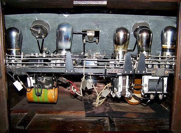
This
receiver was an original development of the Canadian Marconi Wireless Telegraph
Company of Canada. It employed six UV-201A vacuum tubes when production
was first started. There are three RF amplifier stages ahead of the detector
and two AF stages after the detector. The receiver is of the neutrodyne
design and incorporates a special bridge circuit, a design patented
by Canadian Marconi. No details about the bridge are available at this
time.
The
sensitivity of the neutrodyne design allowed the listener to tune
very distant stations and eliminated any RF emissions from the set.
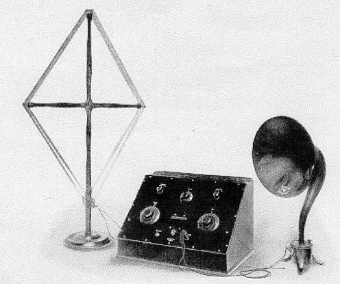
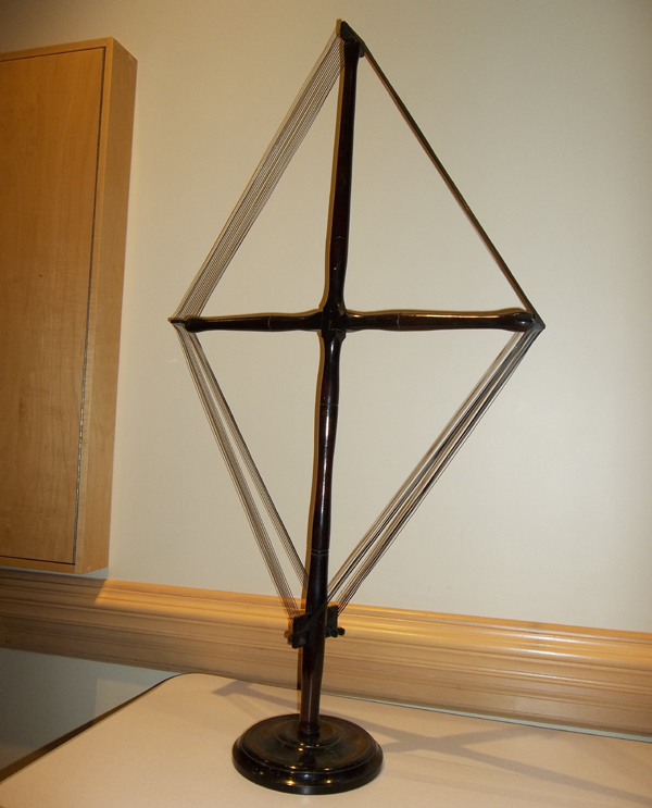
For best results, Marconi recommended that an external loop antenna be
used with the receiver although a wire antenna could be used as well. Interference
from local stations or static could be minimized or eliminated by rotating
the loop antenna.
In
1924, the base price of the radio was $250. Fitted with tubes , A and B
batteries and Splitdorf earphones, the price jumped to $345. If inflation
is taken into account (over 1000% since 1924) then the equivalent cost
of fully accessorized receiver would be around $3,400 in 2008.
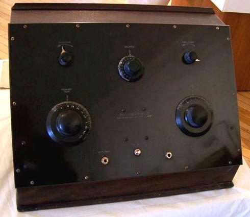
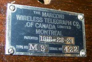
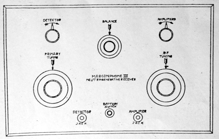
FRONT PANEL MARKINGS
(Note: Serial 442
does not apply to any of the featured radios in this document)
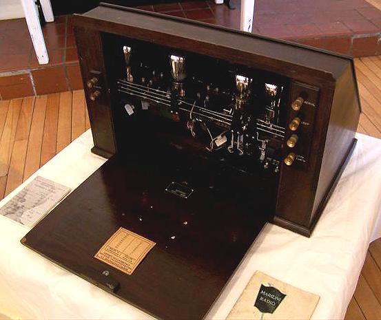
MFG. PLATE ON INSIDE
BACK: 'THE MARCONI/ WIRELESS TELEGRAPH CO./ OF CANADA LIMITED/ MONTREAL/
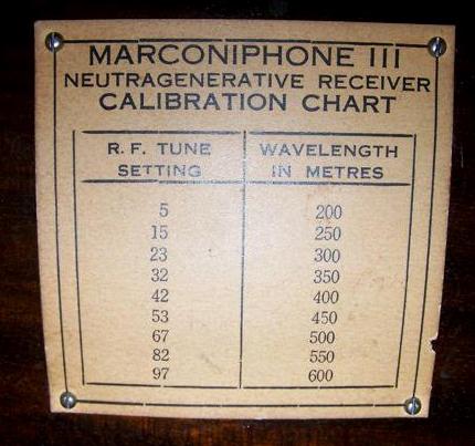
PATENTED1918-23-24/ TYPE NO. M3 SERIAL NO. 442'/ 2 CARDS ON INSIDE BACK:
'Diagram of B Battery Connections for/ MARCONIPHONE III./ [DIAGRAM]' 'MARCONIPHONE
111/ NEUTRAGENERATIVE RECEIVER/ CALIBRATION CHART [SEE SUPP.INFOM FOR COPY]'/
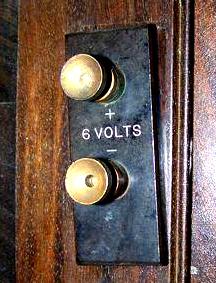
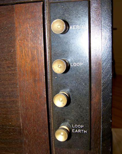
DESIGNATIONS ON KNOBS: 'AERIAL' 'LOOP' 'LOOP/EARTH' '6 VO[?]S/+' 'DETECTOR'
'BALANCE' 'AMPLIFIERS' 'BALANCE' 'AMPLIFIERS' 'PRIMARY/ TUNE' 'R.F./ TUNE'
'DETECTOR' 'BATTERY/ SWITCH' 'AMPLIFIER'/ ON FRONT PANEL: 'MARCONIPHONE
III/ NEUTRAGENERATIVE RECEIVER/ MARCONI/ CANADA'
THEORY OF OPERATION
Wikipedia provides
this explanation of the neutrodyne receiver.
"The Neutrodyne was
a particular type of Tuned Radio Frequency (TRF) radio receiver, in which
the instability-causing inter-electrode capacitance of the triode RF tubes
is cancelled out or "neutralized". In most designs, a small extra winding
on each of the RF amplifiers' tuned anode coils was used to generate a
small out-of-phase signal, which could be adjusted by special variable
trim capacitors. This would cancel out any stray signal coupled to the
grid via plate-to-grid capacitance.
The circuit was developed
in the early 1920's by Alan Hazeltine and used by a group of more than
20 manufacturers that were licensed to produce Hazeltine-Neutrodyne receivers,
This group was known as the Independent Radio Manufacturers. Hazeltine's
invention effectively neutralized the high-pitched squeals that had plagued
early radio sets. The design also neutralized the stranglehold that RCA
then held on the commercial radio industry. Compared to the technically
superior superheterodyne, the neutrodyne was cheaper to build and operate,
and much easier for non-technical owners to use.
To properly set up
a Neutrodyne receiver, not only did the circuitry need to be aligned for
peak performance, (that is, getting all its tuned circuits operating "in
step"), it also had to be neutralized. However, this procedure only needed
to be done once (usually by a serviceman) and thereafter the radio
could be tuned by anyone without special skill, a unique feature at the
time. The neutrodyne was the first commercial receiver suited to use by
the general public. By 1927 some ten million of these receivers had been
sold to consumers in North America".
THE NEUTRALIZATION
TECHNIQUE
Wikipedia also describes
the neutralization technique. To neutralize a Neutrodyne receiver,
the procedure went something like this:
- Turn the receiver
on. Tune the receiver to a strong station near the high end of the dial
(e.g., 1500
kHz)
or use a modulated signal generator set to that frequency and tune the
receiver to it.
- Turn the receiver
off.
- Start with the
final RF stage and work backwards towards the antenna.
- Disable the tube
filament (so the tube is not conducting) either by unsoldering one lead
and taping
the wire
to prevent it from shorting to anything or (preferred) using a neutralizing
adapter between
the tube
and its socket.
- Turn the receiver
on. If you can hear the signal that the receiver is tuned to, that tube
needs
neutralizing.
- Adjust the neutralizing
capacitor for that tube for minimum volume.
- Retune the receiver
for maximum volume.
- Adjust the neutralizing
capacitor for that tube for minimum volume.
- Turn the receiver
off.
- If you disabled
the filament by unsoldering it, resolder the lead.
- Repeat with each
tube until all RF stages have been neutralized.
- The receiver should
be realigned after being neutralized and if it still squeals the neutralization
procedure
repeated.
- It is important
to neutralize using the actual tube that will be in that socket as grid-plate
capacitance
varies some from tube to tube. Also once neutralized the tubes should not
be
exchanged
between sockets. Often replacing a defective tube with a new one required
neutralizing
the receiver again therefore tube replacement usually required a serviceman.
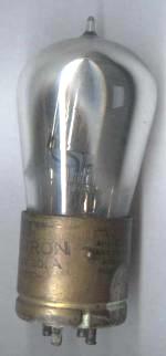
UV-201A TUBE
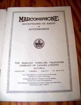
MARCONIPHONE
ELSEWHERE
In 1922, Marconi
UK formed the "Marconiphone" department, to design, manufacture and
sell domestic receiving equipment. This equipment complied with Post Office
specifications and tests, and was therefore awarded the BBC authorization
stamp; initially sets were made at the Chelmsford Works. In December 1923,
the 'Marconiphone' department was formed as a subsidiary of the Marconi
Company. It would therefore appear, that in the UK, the name Marconiphone
was applied to a division of the Marconi company but in Canada Marconiphone
was applied as a specific product brand name.