394G BAND
SELECTION INSTRUCTIONS
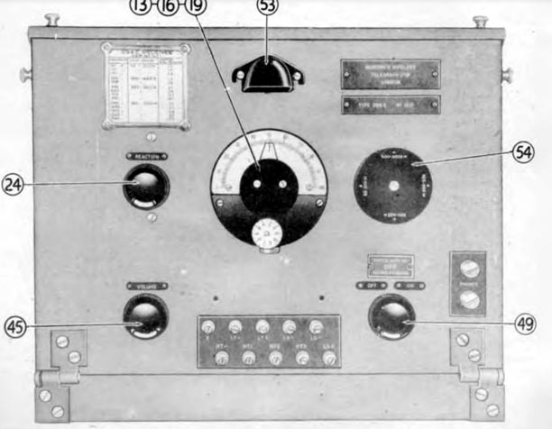
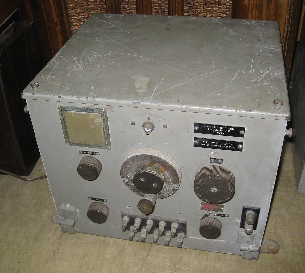
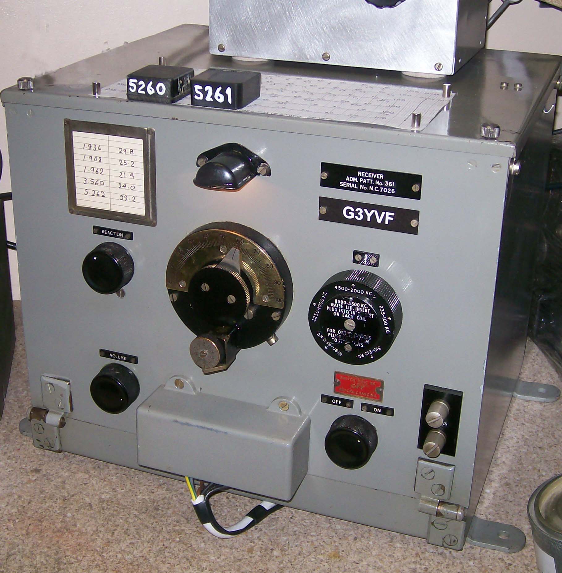
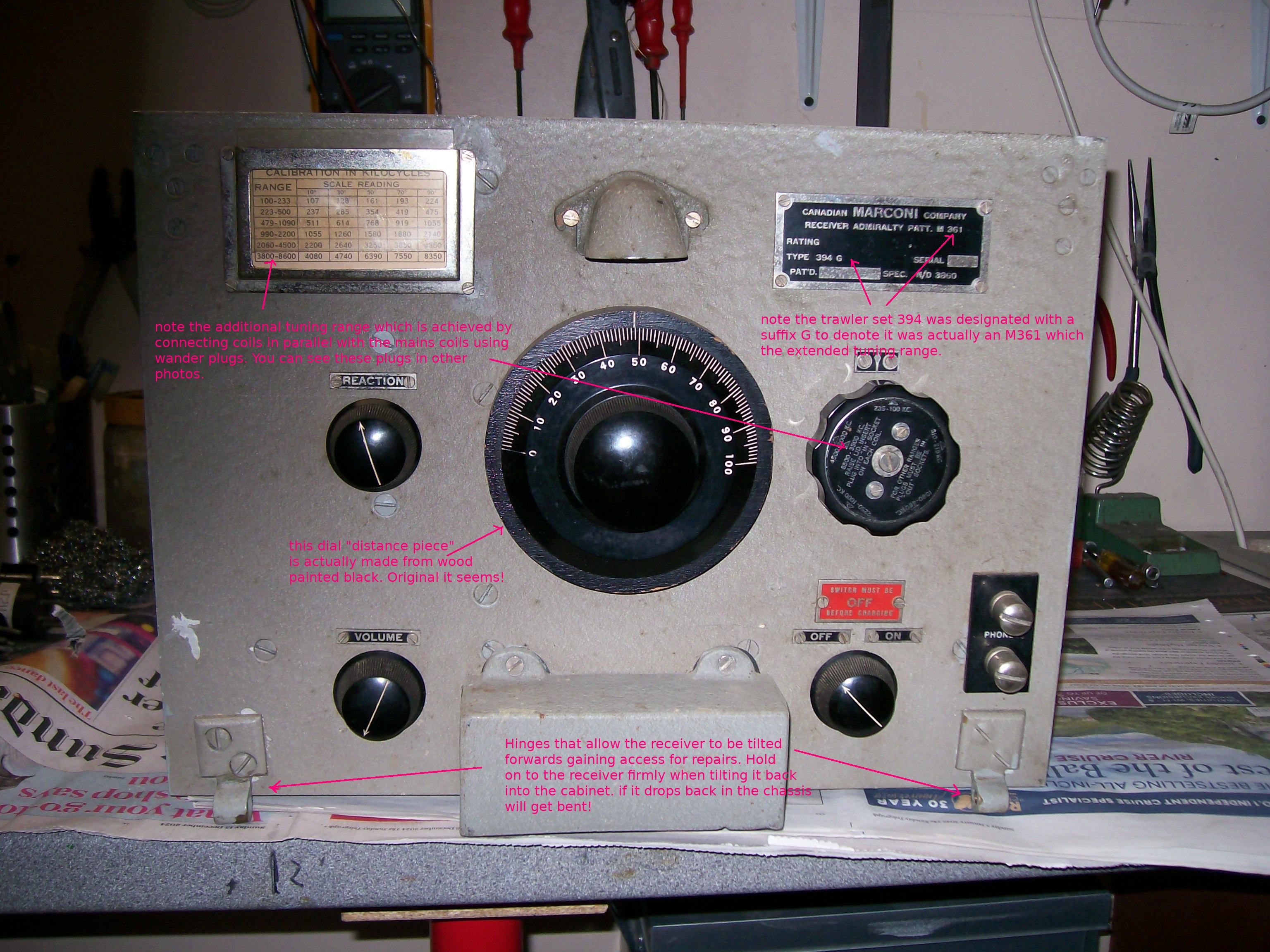
The waveband switching
knob on the 394G has the following instructions imprinted right on the
knob and needs to be followed when wanting to use the highest frequency
range of the set,
8500 -3500KC RAISE
LID INSERT PLUG INTO EACH "IN" SOCKET ON EACH COIL. FOR OTHER RANGES PLUGS
MUST BE IN "OUT" SOCKETS.
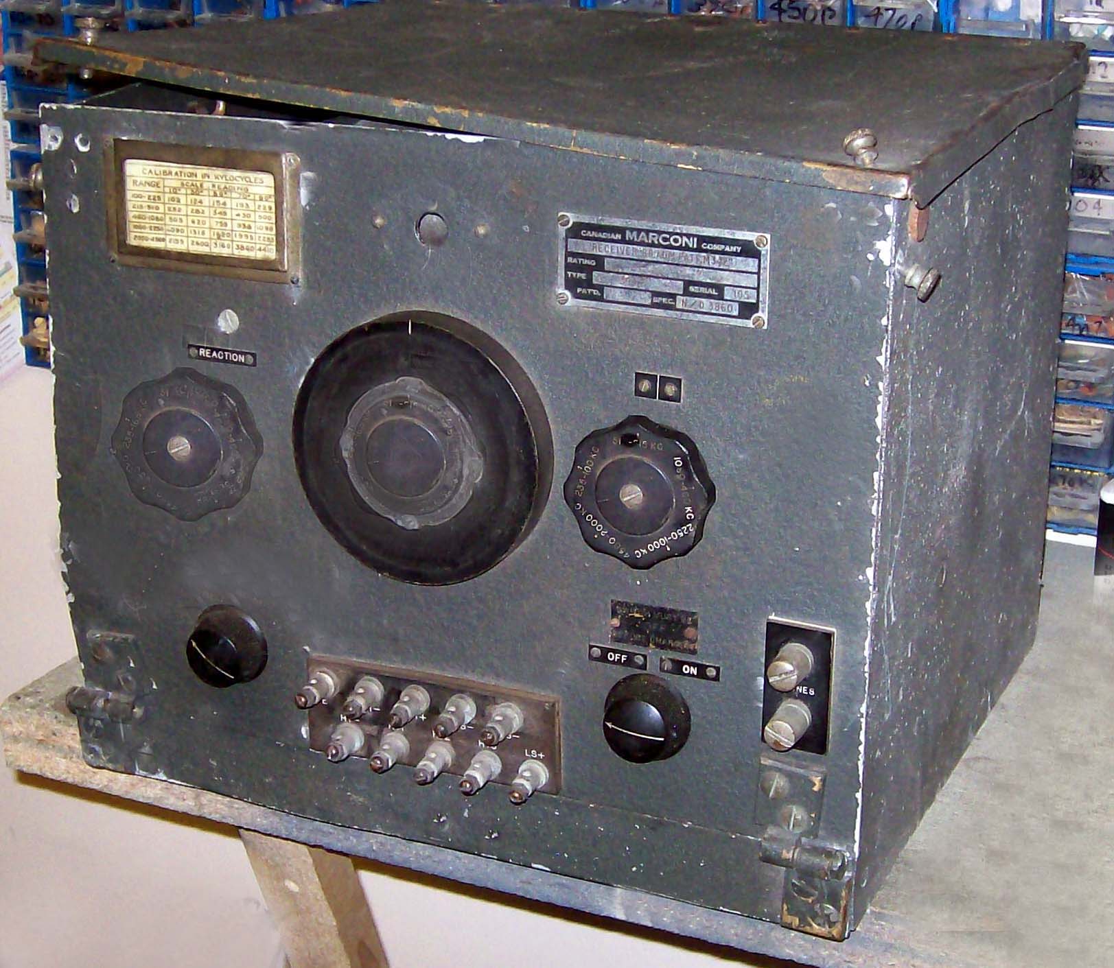
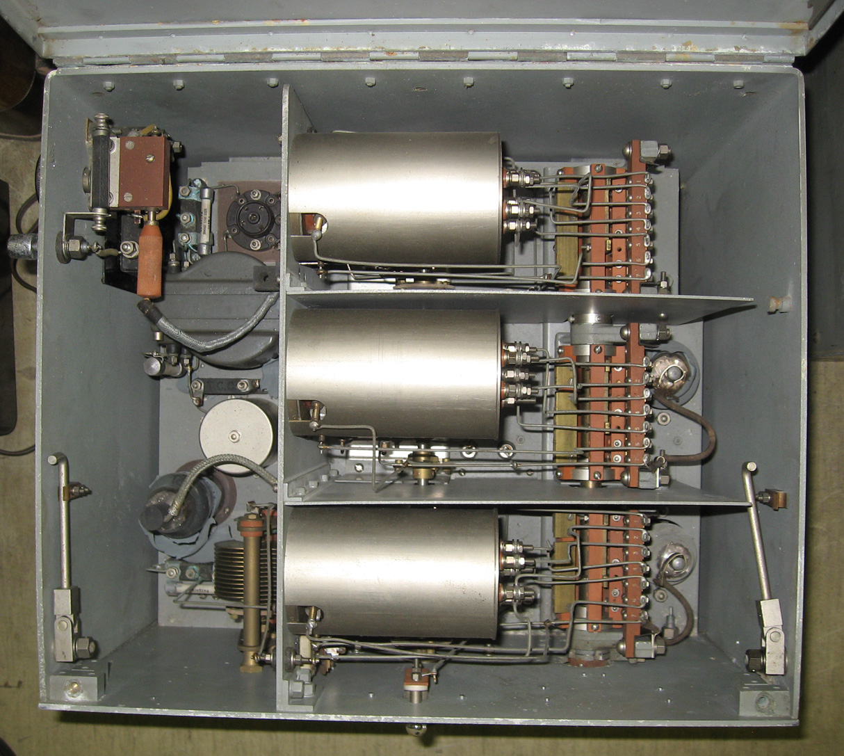
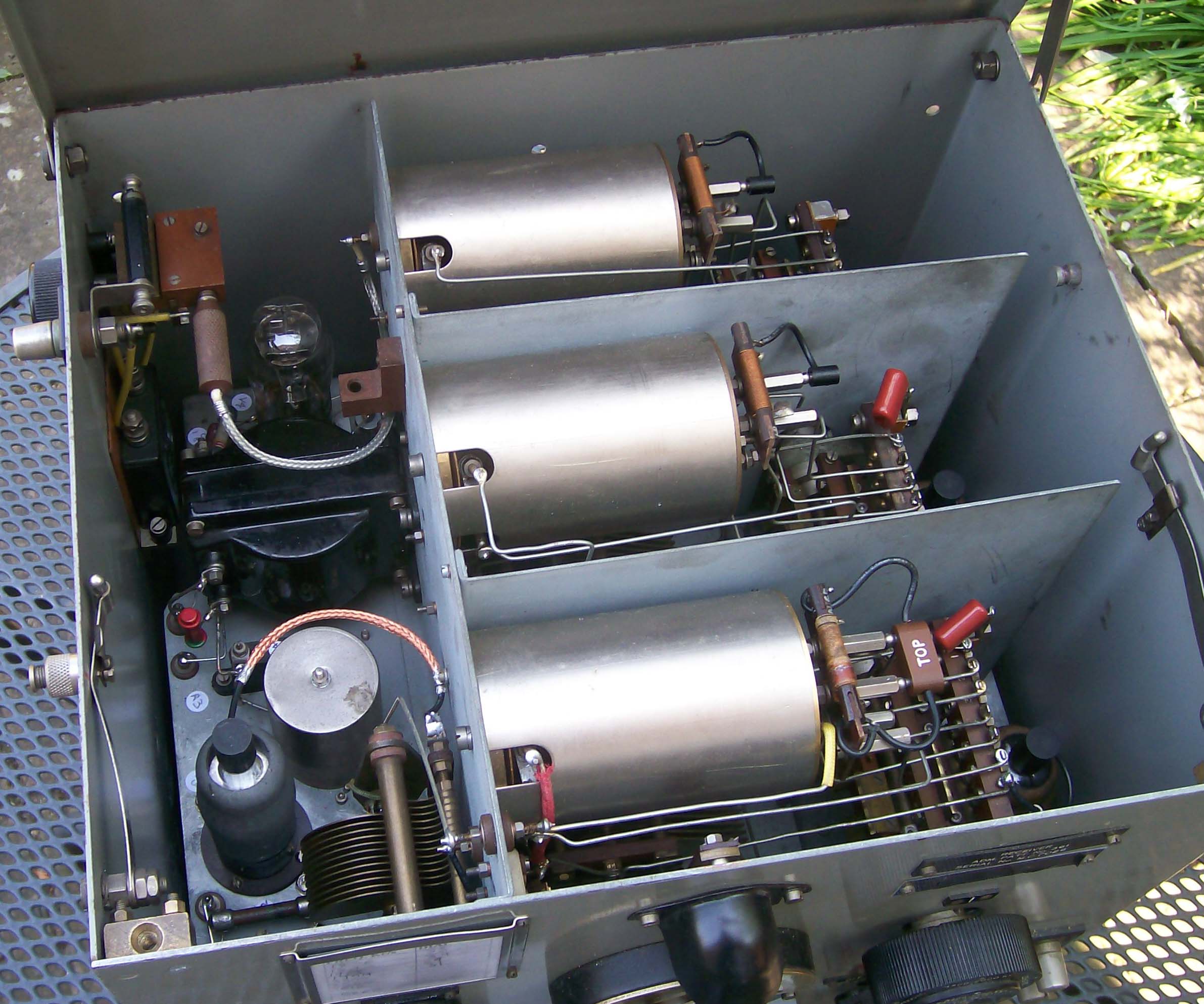
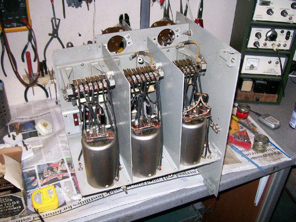
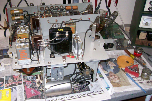
At the end of each
big brass coil container are connections to the wave switch. On the 394G
Admiralty Pattern 361, a small extra coil is fitted across the end of the
brass coil container with a pair of sockets marked "in" and "out" and a
jumper plug patch lead (permanent fixture at the end of each coil) has
to be inserted into the correct socket. Plugs "out" gives the normal tuning
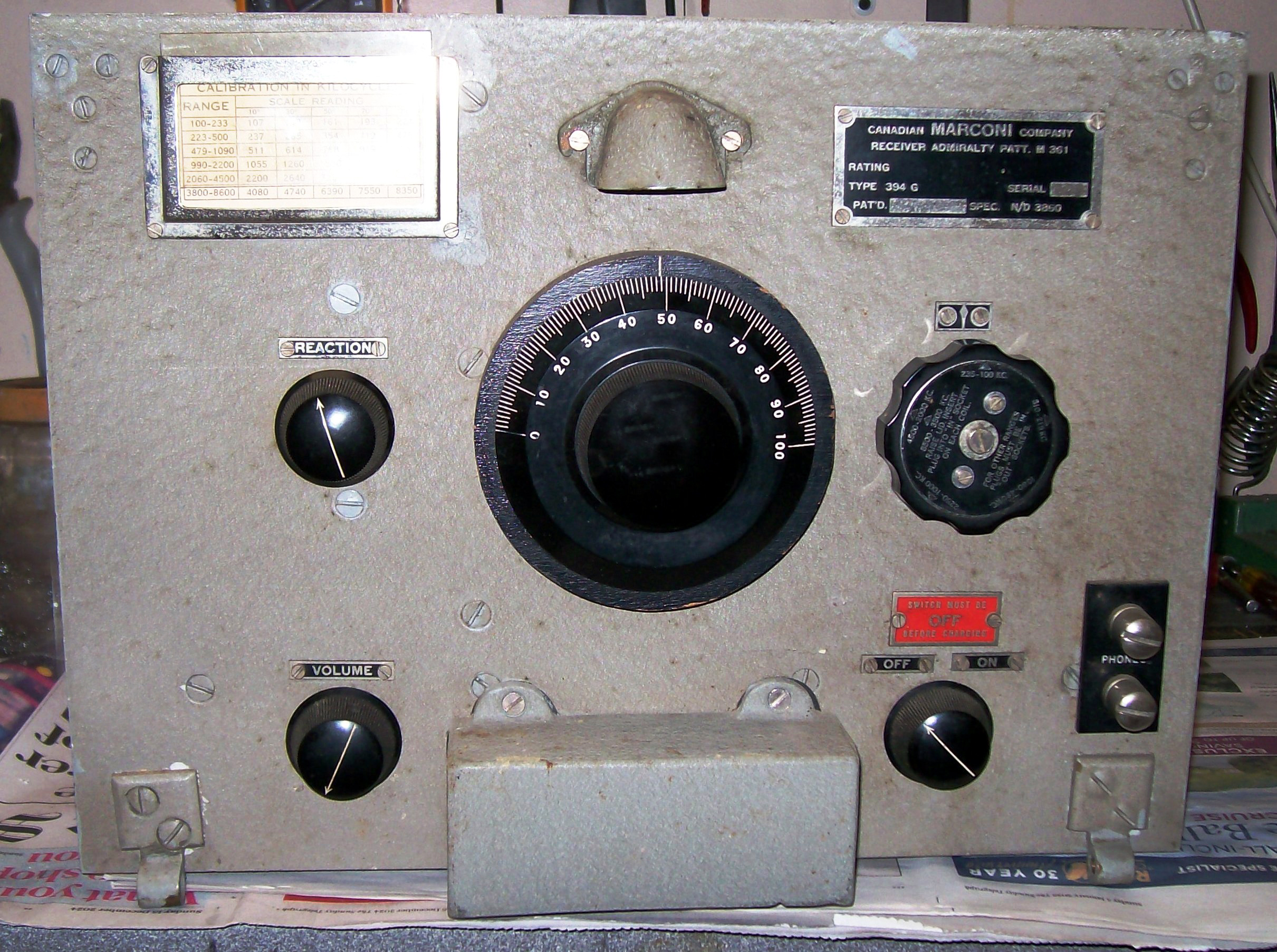
range and plugs "in" gives the 3.5 to 8.5 Mc/s range. The Marconi 394G
is the set that has these plugs and is the one used as Adm.Patt.361
This process must
be reversed in order to restore operation to the frequencies between 100
and 4500 kcs. Nothing can be mounted over the receiver since the lid is
very big and requires at least 2 feet of clearance,
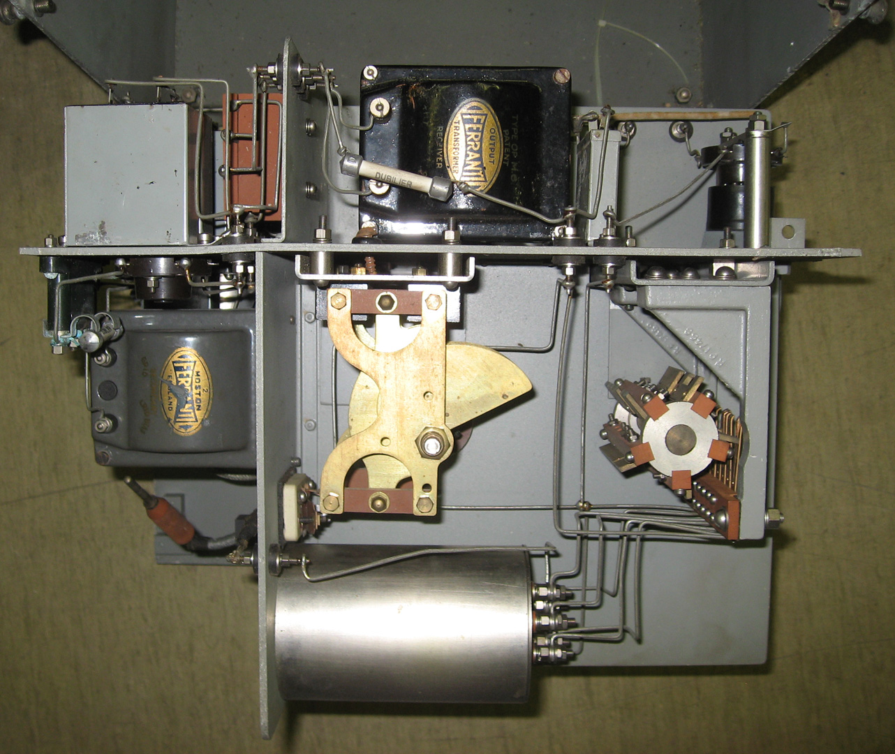
394G LINK
SWITCH
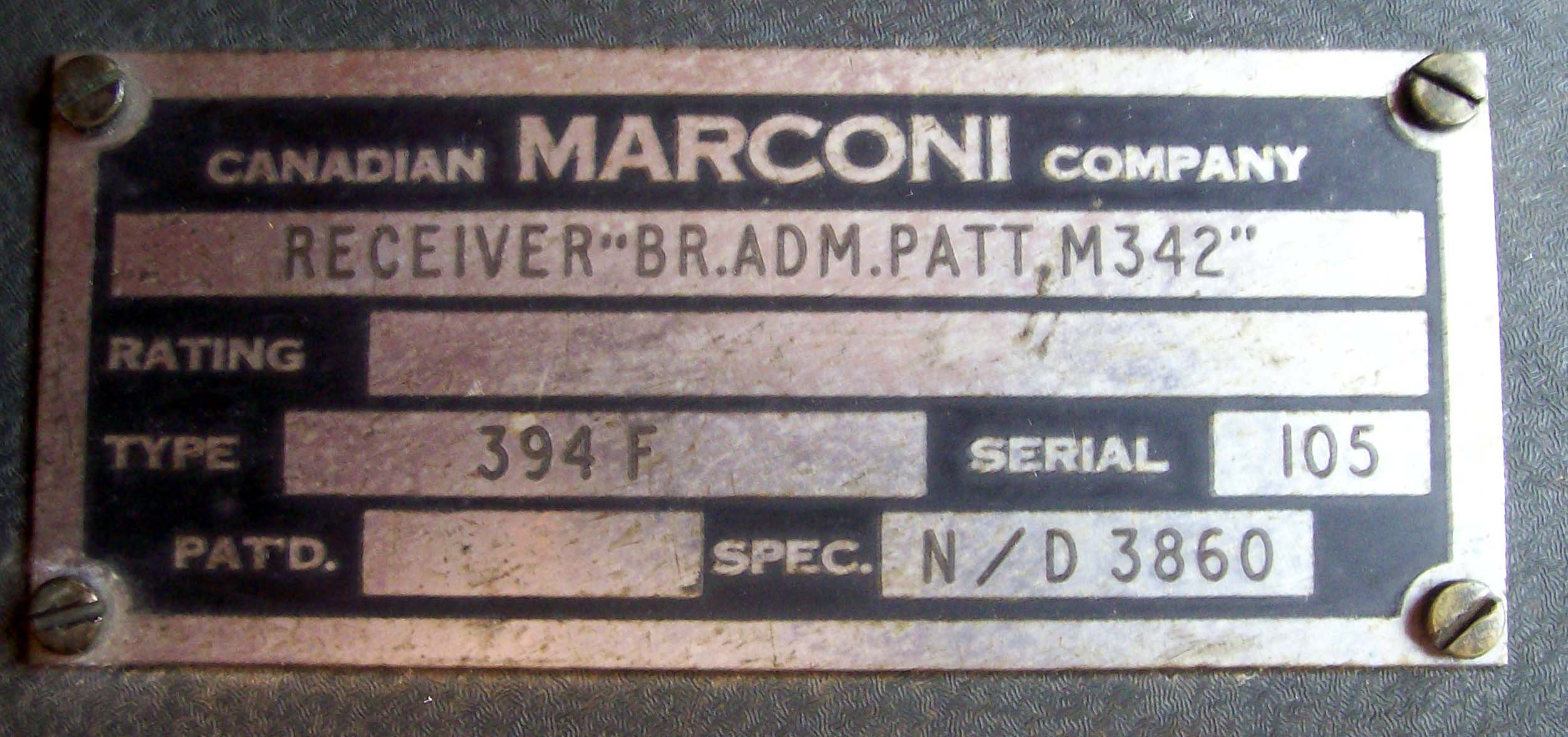
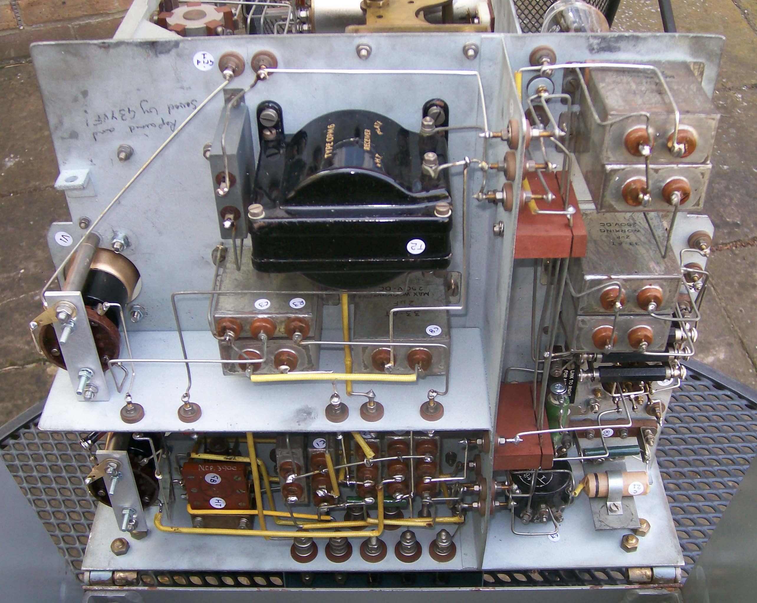
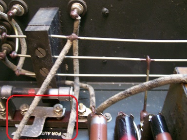
Both the 394F and
394G (A/P342 and A/P361) receivers employ a link switch which is
found under the chassis. Under the metal link is a label which says:
" LINK TO RIGHT
FOR AUTO-BIAS " . This link has to be closed for auto-bias. With this link
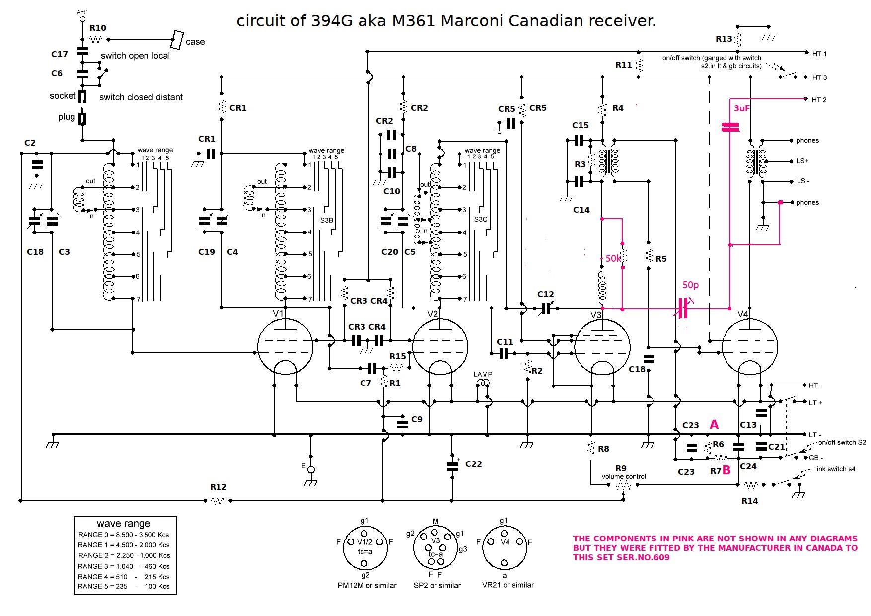
closed, R14 (see the Marconi 394G schematic) is connected from HT-ve to
earth. The HT current now passes through this resistor thus developing
a voltage drop across it. Since it s the -ve lead to chassis/earth it's
used to provide a -ve bias voltage for the grid of the output valve. This
voltage is also supplied to the volume control and here a varying amount
of this bias is applied to the R.F. Amplifier valves thereby controlling
R.F. Gain and hence the output volume. Depending on which output valve
is used, the resistors R6 and R7 have to be changed and Marconi supplied
different resistors with each set for this purpose.
With the Link open,
this auto-bias is not available. Therefore a Grid Bias supply, generally
a battery, must be used. This of course complicates matters... One can
only speculate as to why Marconi did it this way.
394G
COMPONENTS UPDATE
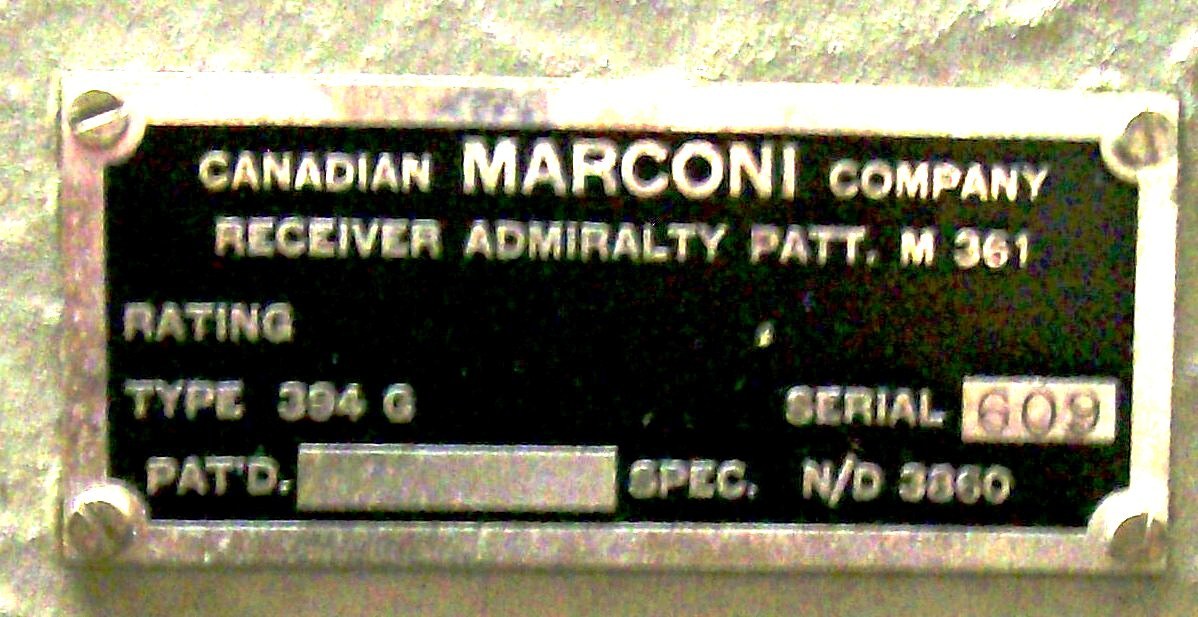
As provided by
Geoff Wooster, t he following is a correction listing for the 394G receiver
Ser.No.609 M361.
Values where possible
were taken from looking at the available information (which was incomplete)
and what was found by looking inside the set without dismantling it! Not
always possible to read the information on the component body or can....some
capacitor values are the best informed guess! C1 does not appear to exist,
not on any drawing or in the set?
T1 3:1 transformer.
T2 45:1 and 15:1 windings.
R1 250K, R2 1M, R3
100K, R4 1K, R5 220K, R6 20K, R7 10K, R8 1K,
R9 2K? R10 250K,
R11 30K, R12 250K, R13 15K, R14 1K.
CR1/2/3/4/5 ARE DECOUPLING
UNITS CONSISTING OF 1K AND 1UF, C2
0.IUF, C3/C4/C5 100P TRIMMERS?, C6 40p, C7 100P, C8/9/10 0.1UF,
C11 100P, C12 300PF
VARIABLE, C13 2UF, C14 100P, C15 2UF, C16 100P, C17 0.1UF, C18/19/20 ganged,
C21/22 25UF, C23 2UF, C24 0.1UF?
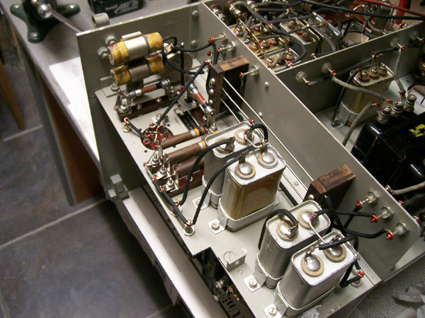
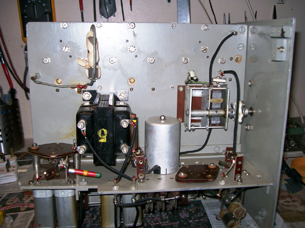
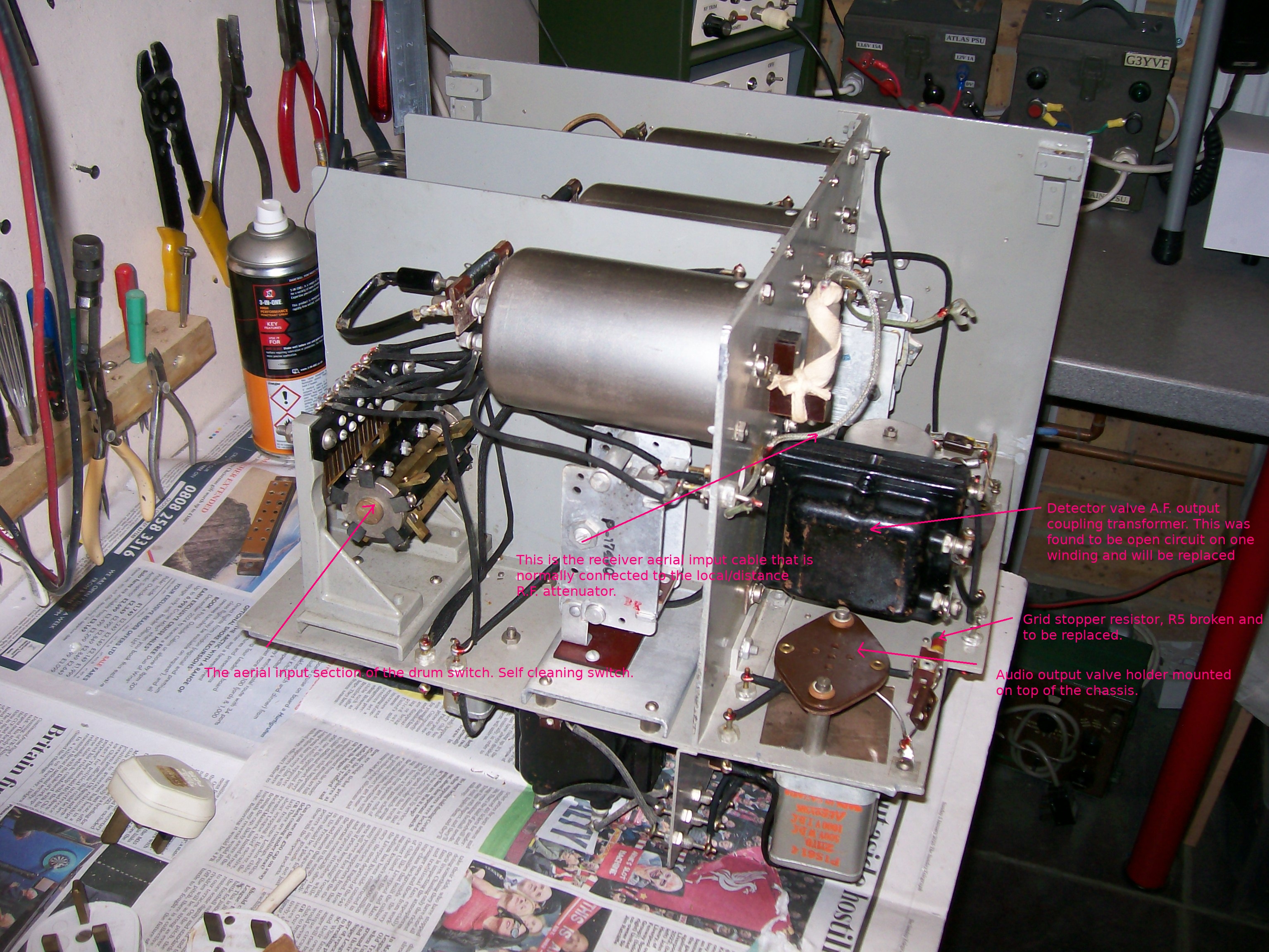
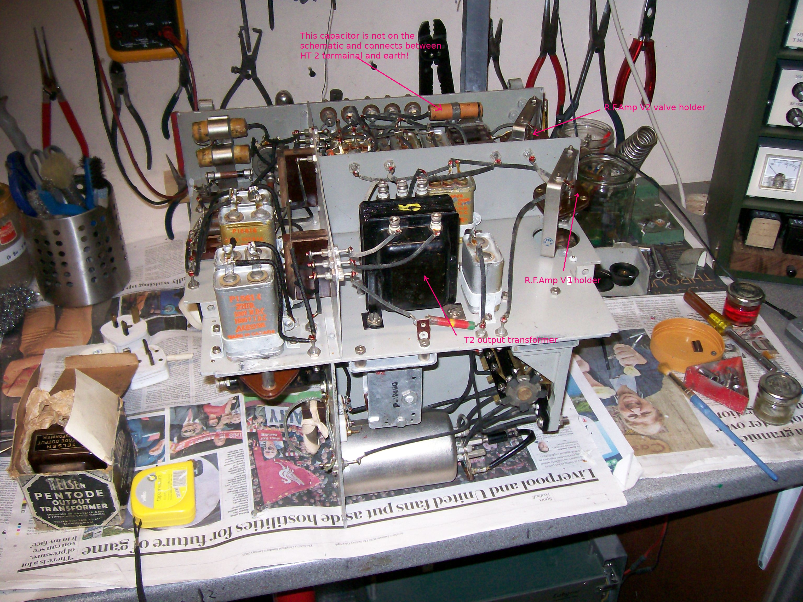
394G COMPONENT EXPLANATIONS
The images in the
table below explain the purpose of the components in the 394G receiver.
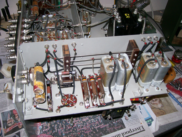
394G BIAS RESISTORS
FOR OUTPUT STAGE
From page 686 of
the book "For wireless telegraphists:
"The bias for
the output valve is obtained from two resistors in series, these resistances
having engraved on their holders the letters "A" and "B." When a
Pentode valve is used as an output valve, resistance "A" should be 1,000
ohms and resistance "B" should be 3,000 ohms. If a P2 power triode
valve is used as an output valve, resistance "A" should be 2,000 ohms and
resistance "B" should be 1,000 ohms. Normally the receiver would be sent
out with this resistance set for a power valve type P2 but a spare 3,000
ohms resistance will be included with the holding down screws for the receiver".
