 |
MDF-5 MFDF Set
|
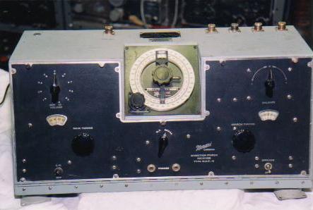
This is a medium frequency, direction finding receiver with a frequency range of 265 to 670 KHz. It is believed that the MDF-5 made its service debut around 1942. The set utilizes the following tube types: 1N5, IT5, 1G4 and IH5, all part of a directly heated filament tube series which was introduced in 1938 and 1939. The MDF-5 specification is 110-617.Serial number 988 is specifically MDF-5-88410 which suggests a family of variants.
USEAGE
After particulars of a station were found in the Admiralty List of Radio Signals, Volume II, and the station tuned in, two zeroes or nulls in the signal being observed would be found by rotating the goniometer with the Sense-D/F switch in the D/F position. Next, with the Sense-D/F switch in the sense position, the goniometer was tuned to the position of one zero and the signal strength of the station was noted. Then the goniometer was turned to the position of the other zero. The weakest of the two signals indicated the true bearing. A finer bearing could then be obtained with the Sense-D/F switch in the D/F position.
Operators eventually preferred the FM-12 MFDF over the MDF-5 once that set was introduced into service. The MDF-5 required a battery or DC source to supply 1.5 volts for the filaments and +90 VDC for the B+ line. It is reported that "SIDOL" copper cleaner was used for cleaning the DF loops.
 |
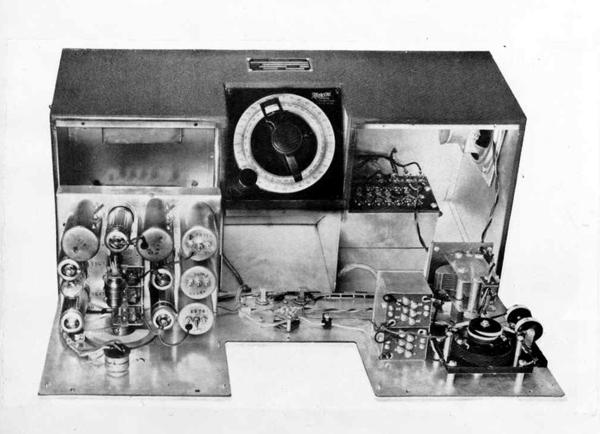 |
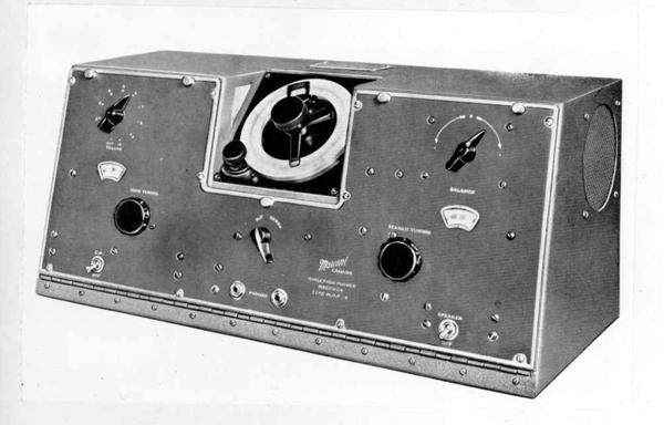
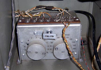
| Above images by Canadian Marconi courtesy Laval Desbiens/Spectralumni. |
 |
| This MDF5 is owned by John Kaminsky and this is how it looked before restoration. (Photo by John Kaminsky) |
 |
| L1 calibration choke. The toggle switch is used to connect the calibration choke to either the fore-aft or the port-starboard loop and the numbers accompanying the rotary switches actually indicate the number of turns of the coil that are connected into the circuit. This is not the only form of L1 that was used. The previous version of the calibration choke does not have the rotary switches. That is pictured above in the Marconi photos. Instead, it uses a terminal board which comprises the entire top side of the L1 box. The rotary switch version must have been a welcome improvement since it was far quicker and far easier to set up. |
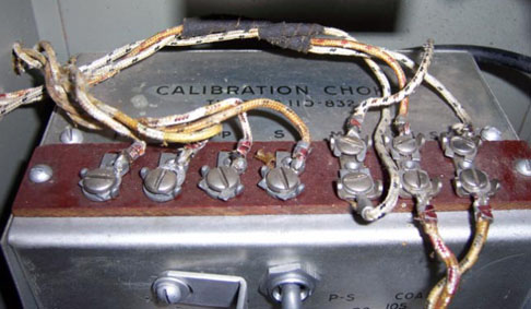 |
| Calibration choke terminal strip. |
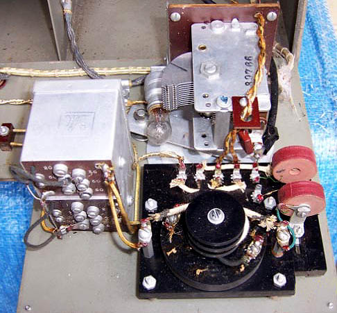 |
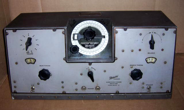
| Balancer and search tuner. |
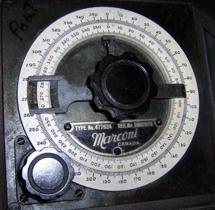 |
| Goniometer dial detail. |
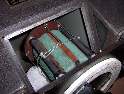 |
| Goniometer coil detail. Here the bottom of the coil is protected with a cloth while the photo is being taken. |
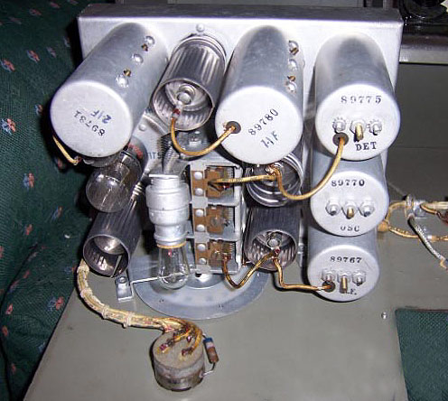 |
| An over-the-chassis view of the receiver. |
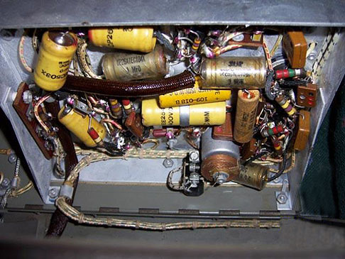 |
| An under-the-chassis view of the receiver. |
| All photos in this table by John Kaminsky |
 |
| Speaker detail. |
 |
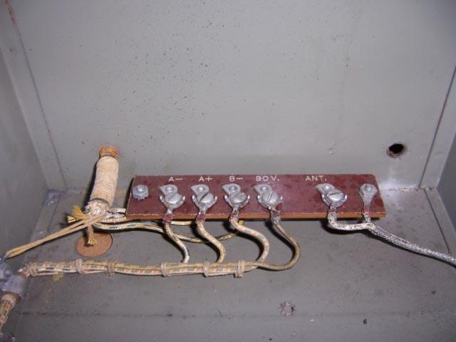
| This fuse block and mains connection was used exclusively for the three pilots lights. |
 |
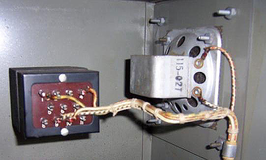
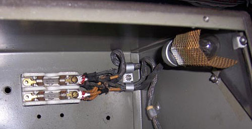
| Battery and sense antenna input. |
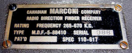 |
| Nameplate detail. Judging by the TYPE data, it makes one wonder if the MDF-5 had variants just like the FR-12 series. Thus far, the following serial numbers have been noted: 988 and 1020. |
| All photos in this table by John Kaminsky |
CASE COLOURS
Note the dark front panel of this example. (Photo by Andre Guibert)
 |
| After sitting in a barn for 60+ years, John Kaminsky's MDF5 cleaned up very well. (Photo by John Kaminsky) |
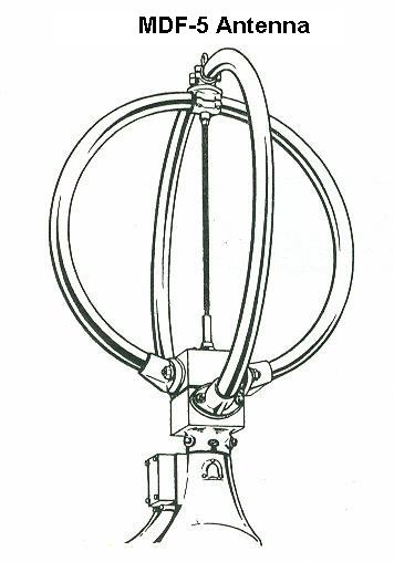 |
| Tom Brent remembers some details about the crossed loops DF antenna which he removed from HMCS Columbia many years ago. "The tubing which forms the loops is actually brass and I'm quite sure there is only a single turn of wire in each one, I do not remember any evidence of multiple turns when I opened up the junction box in the base . Each of the brass loops is electrically isolated from the base of the antenna as well as the other loop The cable which fed each loop had two parallel conductors (not twisted) and was quite substantial in diameter because I remember I couldn't chop it off with wire cutters, I had to use a hacksaw to get through it". (Image courtesy RCN) |
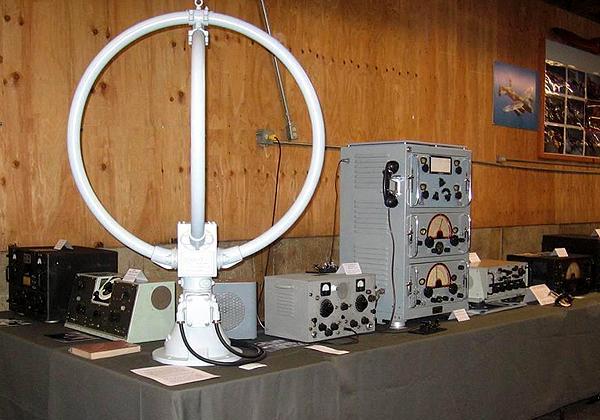 |
| This photo illustrates the relative size of the MDF-5 antenna relative to the MDF-5 set , second form left. The remainder of the equipment , much of it Canadian Marconi is from the collection of Tom Brent. Tom periodically exhibits equipment from his collection at various events. (Photo by Tom Brent) |
| MDF-5
Manual PDF (Courtesy Laval Desbiens via Spectralumni)
MDF-5 Single Sheet Schematic (Courtesy Tom Brent) MDF-5 Tiled Schematic (Courtesy Jerry Proc) MDF-5 Miscellaneous Info (Courtesy Tom Brent) Refurbishing an MDF5 Direction Finder by Gerry O'Hara |
COMMENTS:1) The MDF-5 was acquired under two different procurement numbers. It was MDF-5-88410 for the RCN and 10D/2632 for the RCAF. It is believed that the RCAF procured the MDF-5 for their fleet of marine boats. (To be verified) .
2) The document titled "Miscellaneous Info" is a single page from an RCAF radio equipment catalogue. The acronym SBA appears in the page titles. SBA means Standard Beam Approach. This type of equipment was a landing approach aid which used radio beams to help an aircraft land safely.
Contributors and Credits:1) Andre Guibert <aguibert(at)sympatico.ca>
2) Tom Brent <tgb(at)telus.net>
3) Spectralumni http://www.spectralumni.ca
4) Laval Desbiens <desbiens.laval(at)videotron.ca>
5) John Kaminsky <cap_com(at)sympatico.ca>
6) Gerry O'Hara
Mar 30/22