 |
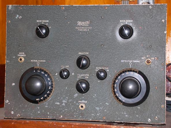
| This example was painted in a dark green, crackle finish and is currently on display aboard HMCS HAIDA. It was not possible to remove the unwanted paint spatter so it was left undisturbed. (Photo by Jerry Proc) |
MSL-5 Receiver
SPECIFICATIONS
Frequency range: 15 KHz to 1550/1775 KHz
Type: Regenerative
Marconi Type: MSL-5 43370A
Marconi Spec: 43365A
Power Source: external battery or DC source. B+ of 90 VDC @15 ma. Filaments 6.3 VAC or VDC at 1.2 amps.
Vintage: 1940This is a four tube, low/medium frequency, regenerative receiver operating in the 15 to 1550 or 15 to 1775 KHz band depending on the variant. This receiver required an external battery supply which was connected to chassis mounted binding posts. Since there was no audio output stage, earphones were required for normal operation. Stations were tuned in by operating two separate tuning controls and two non ganged range switches. For CAW reception, a 1440 Hz note filter was used. One unique feature in this design, was a self-contained crystal radio. Until the early 1950's, it was a requirement of the British Merchant Shipping (Wireless Telegraphy) Regulations that the radio installation aboard a British registered vessel should be capable of 'maintaining reception by means of a rectifier of the crystal type'. Subsequent modification of these rules required the installation of a separate emergency or reserve receiver.
If the MSL-5, or its power source failed, the operator would move the antenna from the binding post marked VAL (valve) to the binding post called CRYS (crystal). Crystal headphones would have to be plugged into a separate front panel jack. An easily accessible, internally mounted, cat whisker crystal would then be manipulated until the most sensitive spot was found, exactly the way it was done with early crystal radio sets. In later MSL-5 models, the cat whisker crystal was replaced with a crystal diode such as the 1N34. In crystal radio mode, stations were tuned by operating the antenna tune control in conjunction with the band switch mounted directly above it. Frequency range is limited to 274-786 KHz while in crystal radio mode.
This receiver was mainly used for the reception of shore based broadcast messages.
COLOUR SCHEMES
Only two colour schemes are known to date.
|
| This example was painted in a dark green, crackle finish and is currently on display aboard HMCS HAIDA. It was not possible to remove the unwanted paint spatter so it was left undisturbed. (Photo by Jerry Proc) |
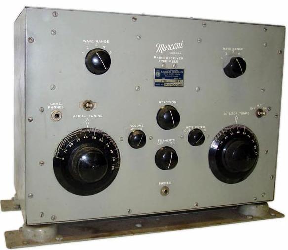 |
| This example, S/N 894, from the collection of Denis Chouinard, is light grey in colour. (Photo courtesy Denis Chouinard ,VE2DSH) |
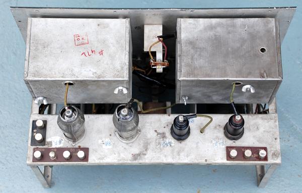 |
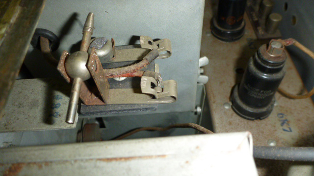
| S/N 472 chassis - top view. The galena crystal detector, normally mounted at the top centre, has been replaced with a 1N34 diode. |
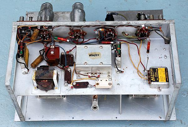
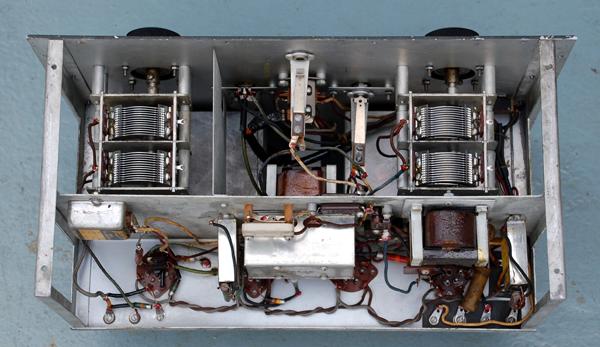 |
| Chassis - bottom view |
 |
| Chassis - rear view. |
| All photos in this table by Jerry Proc |
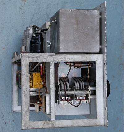 |
| Left side, end. |
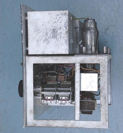 |
| Right side, end |
| All photos in this table by Jerry Proc |
 |
| Closeup of the galena detector. (Photo by Denis Chouinard) |
 |
| Another view of the galena detector. (E-bay photo) |
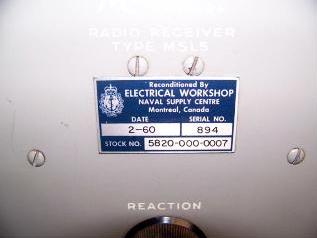 |
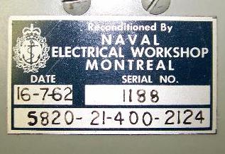
| Above and below: The RCN was still reconditioning the MSL-5 as late as 1960 and 1962 and using them into the 70's. Note the difference in the NATO stock number. (Photos via Le Musée Québecois de la Radio) |
 |
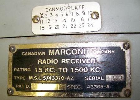 |
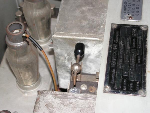
| Nameplate for MSL-5 S/N 1188 with CANMODPLATE. (Photo via Le Musée Québecois de la Radio) |
POWER UNIT
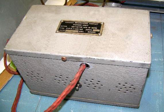 |
| This is the external power supply for the MSL-5, S/N 525. (Photo via Le Musée Québecois de la Radio) |
 |
| MSL-5 power unit nameplate. (Photo via Le Musée Québecois de la Radio) |
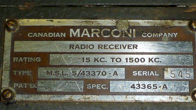 |
| MSL-5 nameplate variant. |
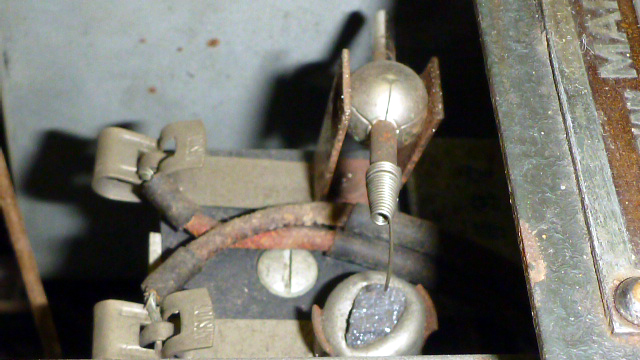 |
| Above and below: Closeup of the cat's whisker detector |
 |
| All photos in this table by Moe Fretz |
DOCUMENTATION
Click on document to download.
MSL-5_Galena detector MSL-5 Parts List MSL-5 Operators Manual - PDF (Courtesy Laval Desbiens via Spectralumni) MSL-5 Corrected Schematic Courtesy VE5ARC. See below
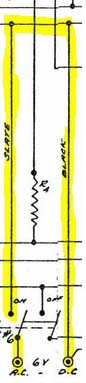
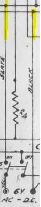
Garnet Moser, VE5ARC, has pointed out that there is a schematic error in the filament wiring for the MSL-5 receiver. Both schematic versions likely exist in the field. The incorrect schematic places a short circuit across the filament supply. The error was just a case of someone putting a connection dot at the wrong wiring intersection.
 |
 |
|
| Incorrect | Correct |
 |
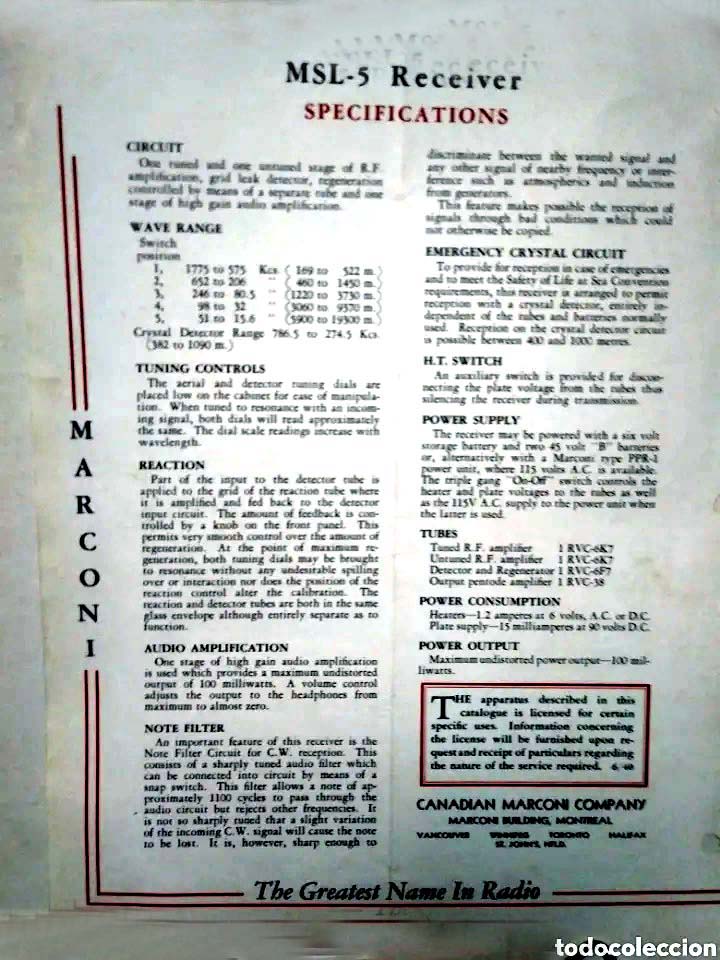 |
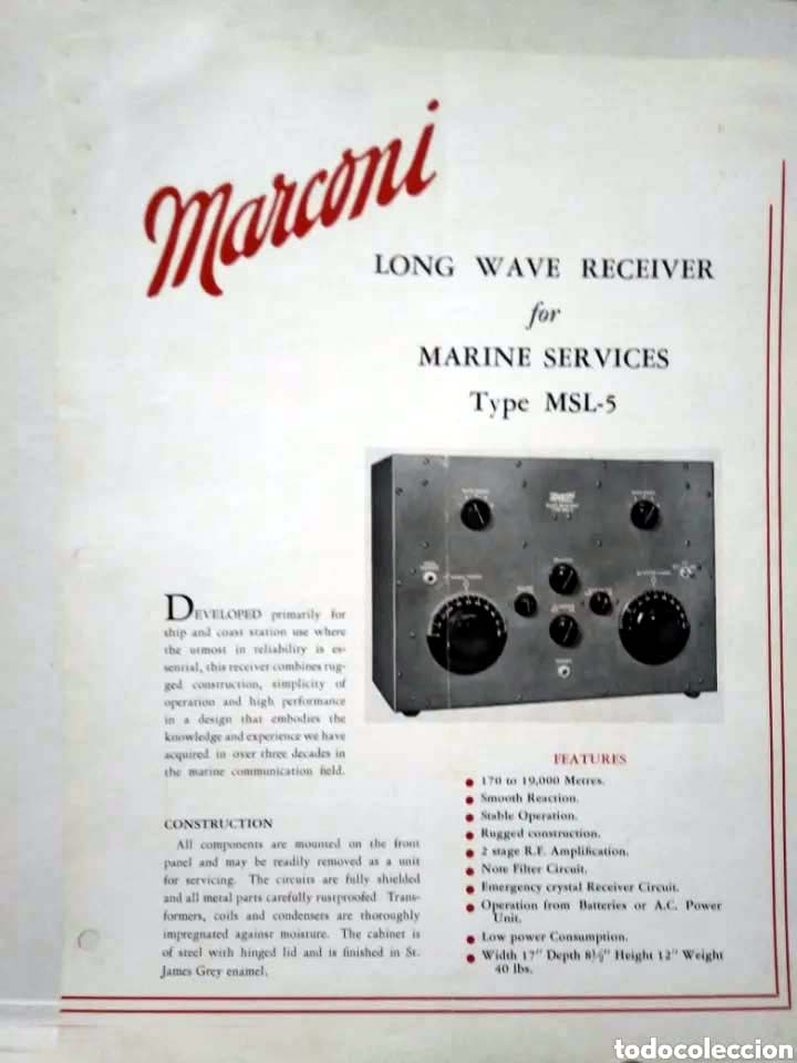
| This is the two page specification sheet for the MSL-5 receiver. It is presented here as a Canadian Marconi artifact rather than a source of information. (Image via Todocoleccion.net) |
Contributors and Credits
1) Denis Chouinard VE2DSH <denischouinard(at)enter-net.com>
2) Le Musée Québecois de la Radio - Jacques Hamel, VE2DJQ
3) Spectralumni http://www.spectralumni.ca/
4) Laval Desbiens <desbiens.laval(at)videotron.ca>
5) Moe Fretz <tubetester(at)gmail.com>\
6) Tito Gomez <2e0dkg@gmail.com>
7) Spec sheet https://www.todocoleccion.net/catalogos-publicitarios/marconi-
antigua-publicidad-radio-marina-canadian-marconi-company~x168627580
July 19/19