 |
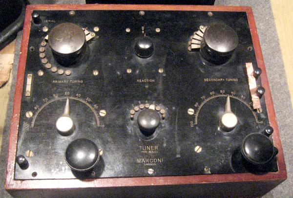
| MST1 Tuner |
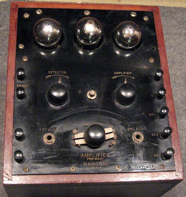 |
| MSA1 Amplifier |
| All photos above by Bruce MacMillan, SPARC Museum |
MST Tuner - MSA Amplifier SPECIFICATIONS
Frequency Range of MST tuner: : 200 to 4,500 metres (1,500 to 66 KHz). The manual also says 200 to 4,000 metres. The schematics indicate 250 to 4,000 metres. Perhaps it was dependent on the variant of the tuner but the manual doesn't explain any of it.
Circa: 1925
Tuner Dimensions: 12" H x 10" W x 14" D.
Tuner Weight: 19 lbs.
Amplifier Dimensions:12" H x 10" W x 14" D
Amplifier Weight: 11 lbs.
Comment: These tuner/detectors were used with the 500 watt Marconi 500WM3 transmitter.GENERAL
Primarily designed as a shipboard receiver, it was capable of receiving both CW and spark signals. The receiver consists of a Tuner Unit (MST) which only has inductors and capacitors and a three tube detector amplifier unit (MSA) employing UV-201A tubes. There is one detector and two stages of audio amplification in the MSA portion. Either one or both stages of audio amplification are operator selectable.
POWER
The tuner/amplifier requires a 6 volt 'A' battery for the filaments and a 45 VDC 'B' battery.
|
| MST1 Tuner |
|
| MSA1 Amplifier |
| All photos above by Bruce MacMillan, SPARC Museum |
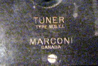 |
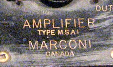
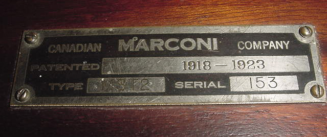
| Closeup of the model numbers. Do not be fooled, That is the number 1 at the end of the model number and not the letter I. The pair reads as MST1 and MSA1. There were several variants in the series. (Image extracts from above photos) |
 |
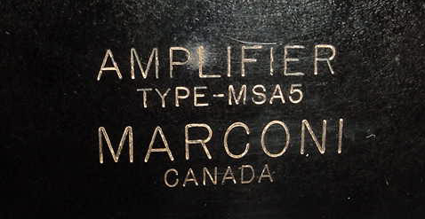
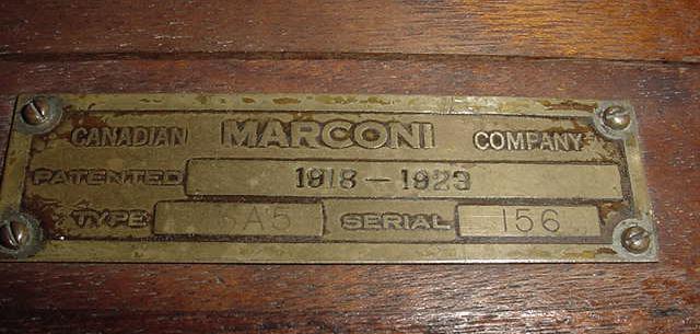
This pristine MST2 Tuner/MSA5 Amplifier combination is held in the collection of Jean Thériault in Quebec. Note the major differences between the MSA1 amplifier above and MSA5 amplifier below. The tuners appear identical in spite of bearing a different variant number. Canadian Marconi did not discuss the different variants in their manual.
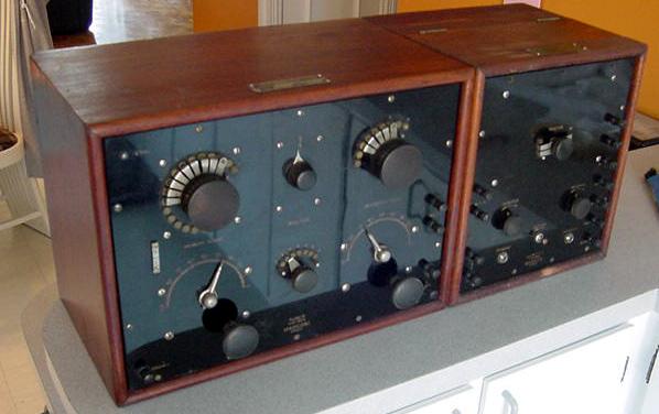 |
| MST2 Tuner/MSA5 Amplifier mounted in wooden case. |
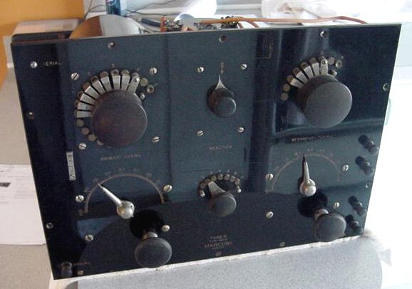 |
| MST2 tuner extracted from case. |
| All photos in this table by Jean Thériault. |
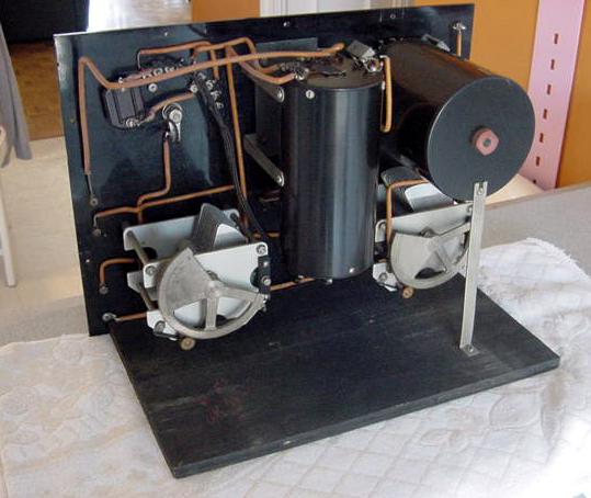
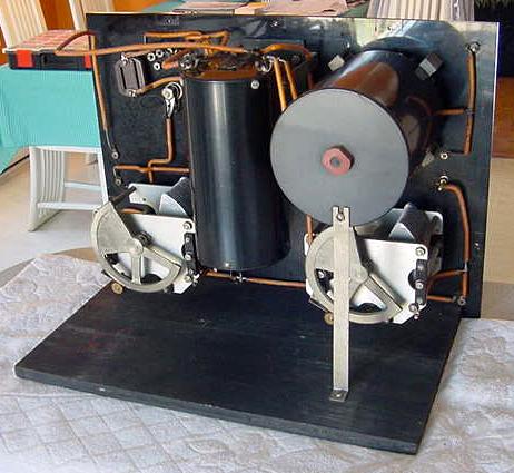
| MST2 TUNER - INTERNAL VIEWS |
 |
 |
 |
| All photos in this table by Jean Thériault. |
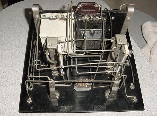
| MSA5 AMPLIFIER - INTERNAL VIEWS |
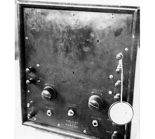 |
| MSA5 amplifier (Science and Technology Museum image) |
 |
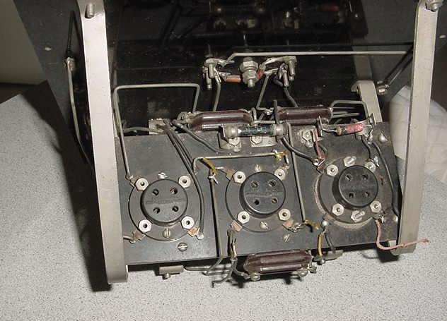 |
| The three tubes are missing in this view. |
 |
 |
| All photos in this table by Jean Thériault. |
| MST-MSA Manual (Courtesy Laval Desbiens via Spectralumni) |
Contributors and Credits:1) Bruce MacMillan VE7MT <radio(at)telus.net>
2) Spectralumni http://www.spectralumni.ca/
3) Laval Desbiens <desbiens.laval(at)videotron.ca>
4) Jean Theriault <jean-1943(at)videotron.ca>
5) MSA5 anplifier https://ingeniumcanada.org/ingenium/collection-research/collection-item.php?id=1970.0107.001
May 22/11