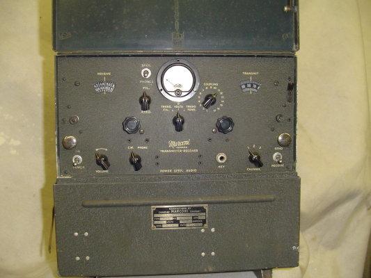
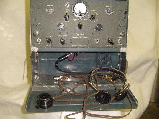
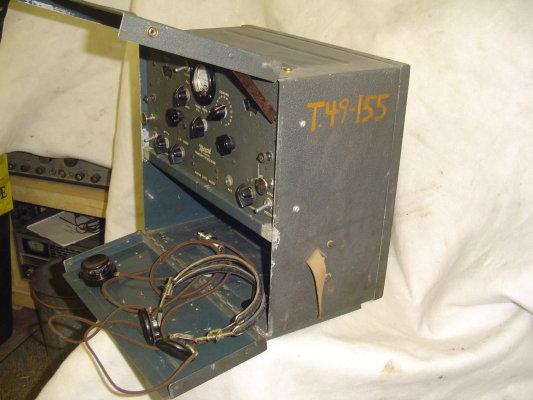
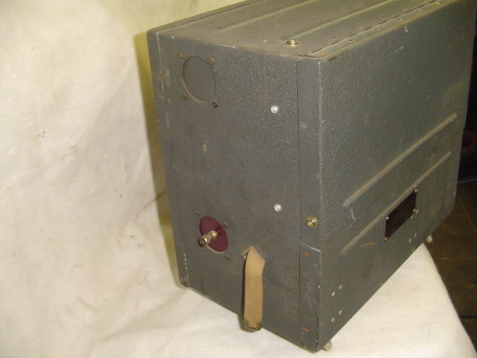
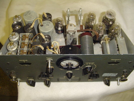
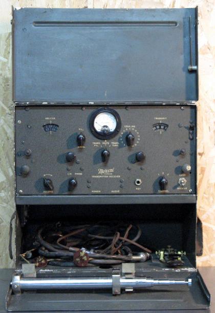
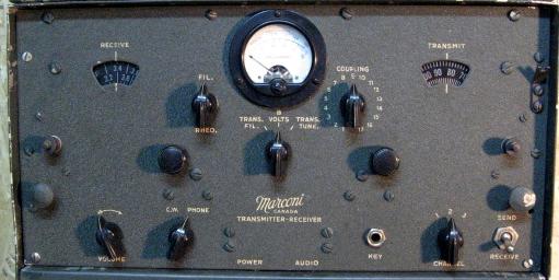
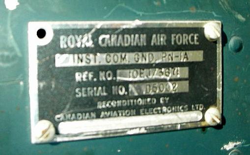
PN1-A and PN1-B
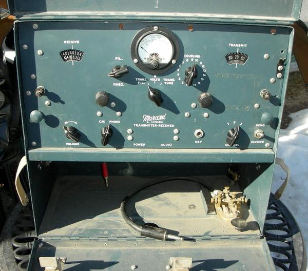
Transmitter/Receiver
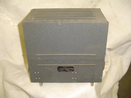
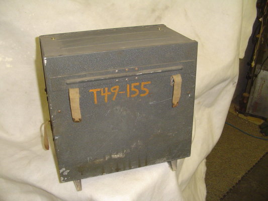
Type: Portable Transmitter-Receiver
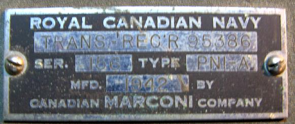
Variants: From nameplate
data, the PN1 comes in -A and -B versions. The A model was a manpack
version with a telescopic antenna while the B model was the fixed
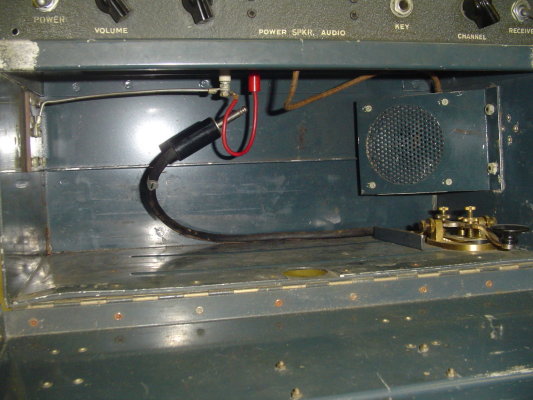
station version. PN-1B has no telescopic antenna but has a built in speaker.
Frequency Range:
3000 to 6000 KHz.
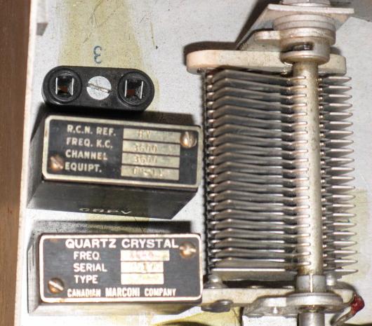
Frequency control
: 3 crystal controlled frequencies
Sample frequencies
actually used: 3480, 3600, 4172 and 4850 KHz
Transmitter Power
Output: 2.5 watts
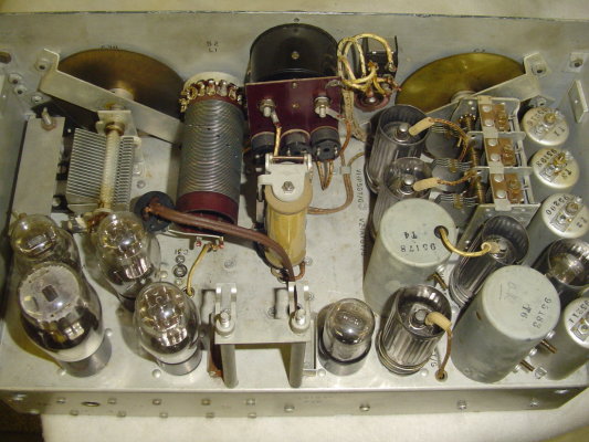
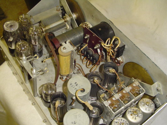
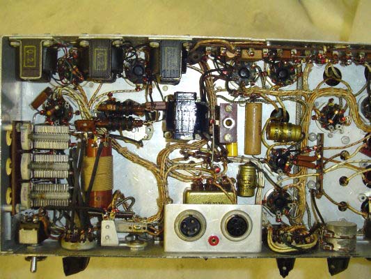
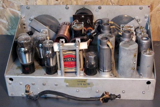
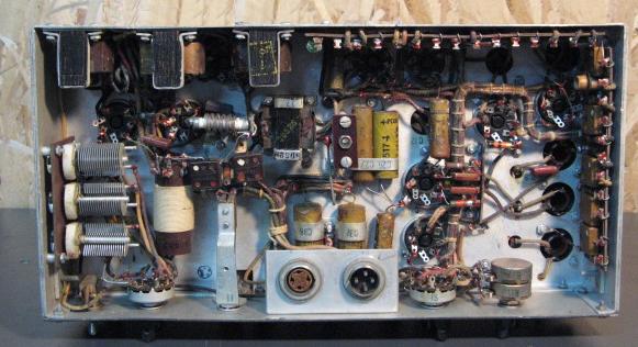
Tube Lineup: 2 x
1P5, 1A7, 1G4, 1H5, 1Q5, 1J6, 1H4, 1J6 and 1F5
Vintage: Believed
to be 1940
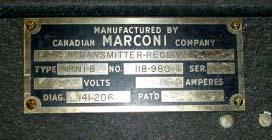
Marconi type no:
118-980
Diagram: 141-206
(also see #99380 on the chassis of the PN1-A)
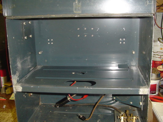
Dimensions: 15 1/2
" tall 15 1/2" wide
9 1/4" deep
Weight: 11.15 KG
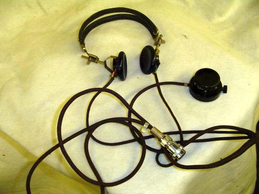
(24.6 lbs) with phones, mike but without battery.
Telescoping antenna:
14 inches collapsed. 72 inches extended.
Power: Light duty
'B' battery 180 VDC and 3 volt 'A' battery - 6 to 8 hours
Heavy duty 'B' battery 180 VDC and 3 volt 'A' battery - 60 to 80 hours.
If the 'A' battery drops below 2 volts or the 'B' below 120 volts,
then a battery replacement is required.
Also requires a 3 volt 'C' battery.
Comment: One of
two sirviving examples of a PN1A serial 189) is now located at 25 Canadian
Forces Supply Depot in Montreal
Credits and Contributors:
1) Moe Fretz <tubetester(at)gmail.com>
Collection and Preservation Of Canadian Tube Radios, Communication Equipment,
Vintage Ham gear and Military Radios.
2) Jason Racine
<thebuckhunter(at)cogeco.ca>
3) Bruce MacMillan
<bruce_macmillan(at)telus.net>
4) Garey Valcourt
5) https://www.ve3kbr.com/photo_albums/marconi_pn1a_album.htm
6) Cliff Chapman
[chipperc524(at)gmail.com]