 |
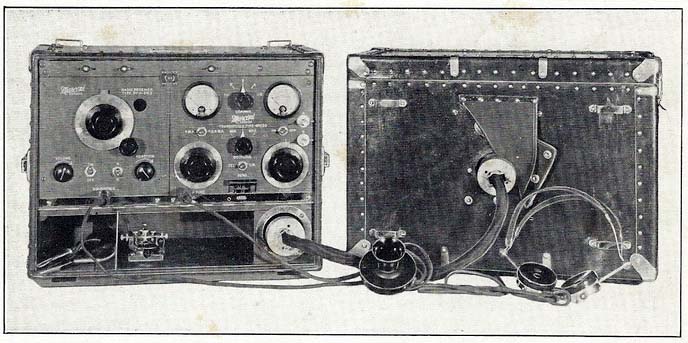
| PRS1 transmitter/receiver. |
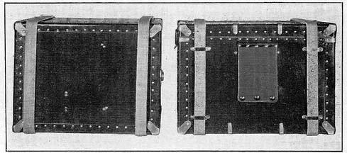 |
| PRS1 secured for transportation |
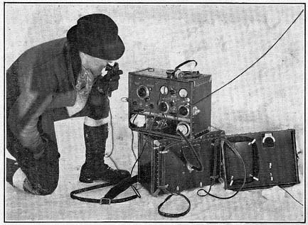 |
| PRS1 in operation. |
| All images in this table courtesy Canadian Marconi |
PRS1 Transmitter Receiver
SPECIFICATIONS
Frequency range:
Transmitter - Factory default for the transmitter is 166 to 184 metres. (1807 to 1630 KHz)
Optional coils can be purchased to make the transmitter operate between 53 to 200 meters (5660 to 1500 KHz)
Receiver - Factory default is 162 to 187 metres. Optional coils can be purchase to extend the frequency range from 41.1 to 200 meters (7300 to 1500 KHz)Type: Transmitter/Receiver
Modes: CW/Telephony (up to 50 miles)
Power output: Up to 7 watts on CW
Power unit weight: 63 pounds
Transmitter and receiver weight: 32 pounds
Power output stage: Uses two RVC802 tubes
Vintage: ?TRANSMITTER
Despite its simplicity and compactness. the transmitter is comparable in performance with much more elaborate assemblies. Two rugged valves (RVC 802 are used in a unique circuit embodying a stable pushpull oscillator electron-coupled to a push-pull power amplifier. As the oscillator normally remains fixed in frequency, only the antenna and amplifier plate tank need be adjusted for various antenna conditions.
The normal waverange of the transmitter is 166 to 184 metres. However, additional coils may be supplied to permit of operation on any frequency between 53 and 200 metres.
RECEIVER
Sensitivity and ease of adjustment ate the main characteristics of the receiver. Two RVC 6D6 valves function as an R.F. stage and regenerative detector respectively. An RVC 6F7 valve acts as two stage resistance coupled audio amplifier. The plate supply to these valves is obtained from a small 45 volt 'B' battery contained in tbe receiver unit. The filament supply is obtained from the storage battery in the power unit. .
The waveband of the receiver is 162 to 187 metres. Additional plug-in coils can be supplied for any wavelength between 41.1 and 200 metres.
ANTENNA
Both transmitter and receiver are arranged to operate with the same antenna system. The equipment may be used with antenna and ground, antenna and counterpoise, or with feeder coupled antenna. A generous loading coil with front panel adjustment permits considerable latitude in antenna length and height.
POWER SUPPLYThe power supply consists of two, light weight, non-spillable, 6-volt storage batteries, a light weight dynamotor, a switch and fuse
panel. The batteries power the filaments of all tubes. They also drive the dynamotor, either in series or in parallel, as desired. This change
is effected by means of an easily accessible knife switch. When the batteries arc in series, the dynamotor delivers a plate voltage of 300 volts to the transmitter This results in a carrier output of 2.5 watts on telephony and 5 watts on CW. When in parallel, the plate supply is 150 volts
volts and the carrier outputs are 0.4 and 0.7 watts respectively..The storage batteries have a capacity of 40 ampere hours each and can be completely recharged in approximately twelve hours. With reasonable care, fully charged barrettes will ensure between 7.5 to 16 hours of operation, depending upon whether high or low power is used and assuming the time is equally divided between transmission and reception.
The batteries may be charged either in series or in parallel from any charging device suitable for 6 or 12-volt batteries. If no facilities for charging are available either of the following can be supplied
a) A small gas engine driven generator. The gas engine is of the four cycle air-cooled type running at 1750 r.p.m. and operates for about 12 hours on a gallon of gasoline. The generator is coupled to the engine and is equipped with cutout , meter and a switch.
(b) A windmill charger which will supply the correct amount of current in a wind exceeding 10 miles per" hour. The device is equipped 'with a centrifugal governor, a. cutout, and an overload relay. It is entirely autonatic in operation.
VALVES
Receiver - Two type RVC 6D6 and 1 type RVC 6F7 valves.
Transmitter - Two type RVC 802 valves.APPROXIMATE DIMENSIONS AND WEIGHTS
| UNIT | WIDTH | HEIGHT | DEPTH | WEIGHT |
| Receiver Supply Unit | 18 in. | 14 in. | 10 in. | 63 pounds |
| Transmitter-Receiver Unit | 18 in. | 14 in. | 10 in. | 32 pounds. |
|
| PRS1 transmitter/receiver. |
|
| PRS1 secured for transportation |
|
| PRS1 in operation. |
| All images in this table courtesy Canadian Marconi |
Contributors and Credits:
1) Jacques Hamel < hamja(at)videotron.ca>
2) Canadian Marconi PRS1 brochure extracts.
Mar 23/18