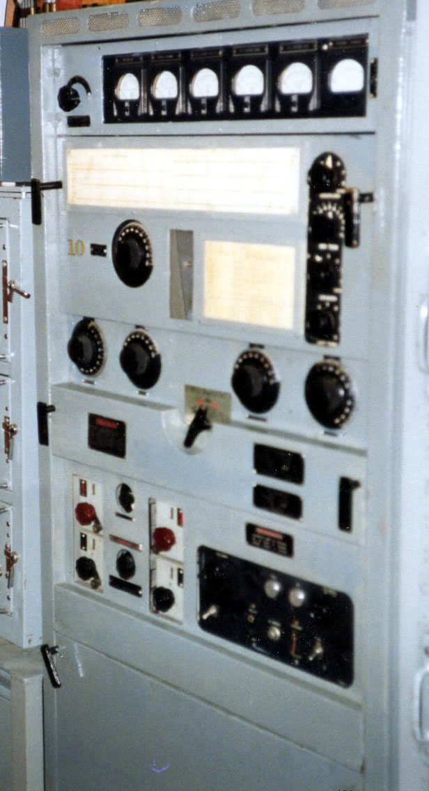
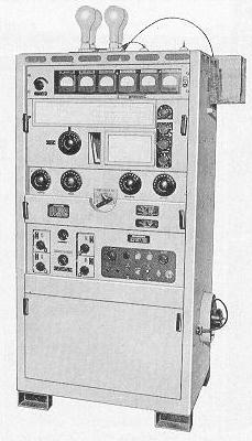
PV-500 HM Series Transmitter


GENERAL

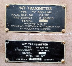
The Canadian Marconi PV-500 HM, was first delivered in 1943. It was a high powered, CW/ICW (Interrupted CW) only transmitter, capable of operating in the range 3 to 19 MHz. It saw shipborne service with the Royal Canadian Navy in WWII and well into the 1960's. The PV-500 series also saw service in Canada's SUPRAD (SIGINT) system as a "flash message" transmitter in the 1950's.

Power input was essentially 500 watts over this frequency range. The HM2 variant of the PV-500 operated up to 28 Mc, however, power input was reduced to 300 watts above 19 Mc. 
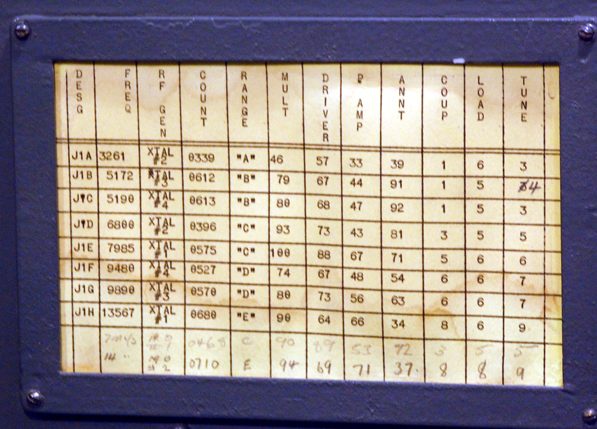
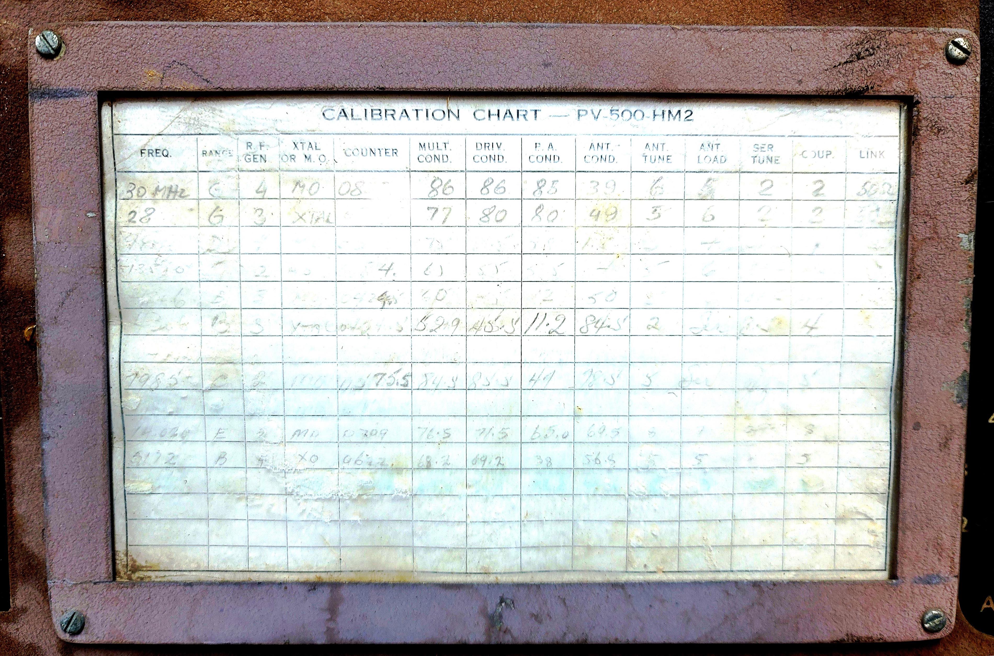
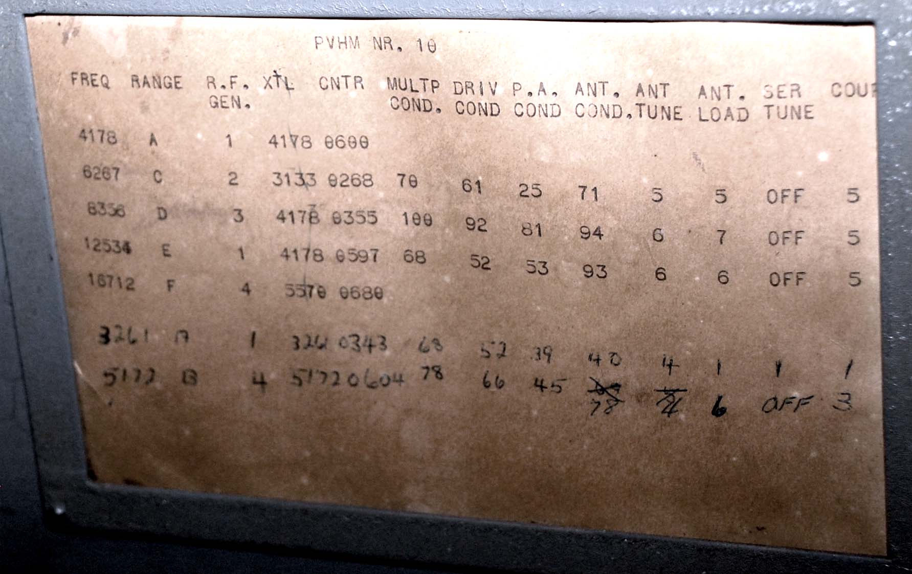
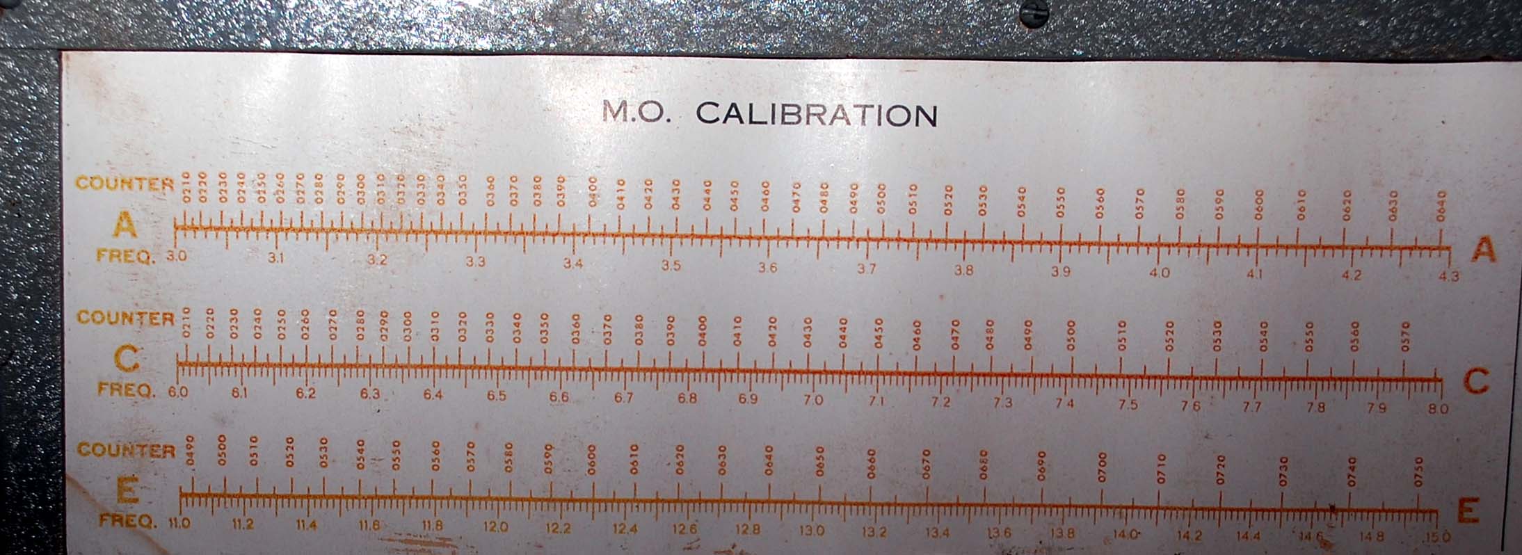
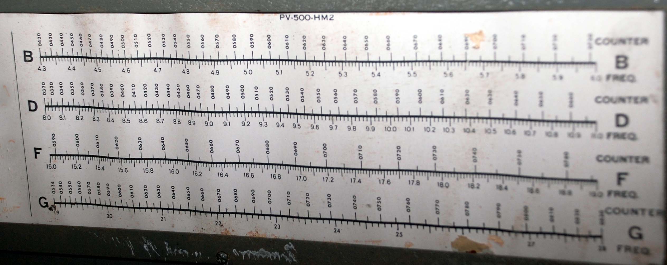
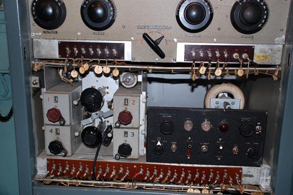
There were four, switch selectable, master oscillators that could be preset to the most often used frequencies. Alternately, four crystal controlled frequencies were also available. Interrupted CW (or MCW as its more commonly known) could be sent using tones of 400, 700 or 1000 Hz. In talking with former naval telegraphists, there is no evidence to support the use of ICW.

In later variants, the PV-500 was adapted as a ship-to-shore FSK (Frequency Shift Keying) transmitter or RATT service as it was called in the RCN. When used in RATT service, the PV-500 was keyed by a FS keyer which was connected to a Baudot Transmitter-Distributor (paper tape reader).

A front cover note in manual BRCN 5423 indicates that type 96935 (PV-500 HM) was modified to the HM2 variant by Canadian Aviation Electronics Ltd. This would suggest that the variants of HM2 and higher were not produced by Marconi but were field modifications done by the RCN under contract.
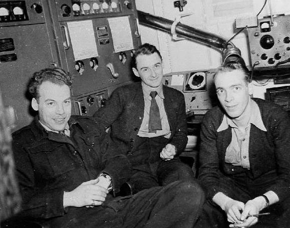
Keith Kennedy, of Surrey B.C served in the RCN. He states that "PV-500's were notorious for ground loop problems and one made sure that you kept one hand in your pocket while tuning them. Placing your hand on the cabinet to brace yourself against the ships roll could result in a really fine 'attention grabber' in the 
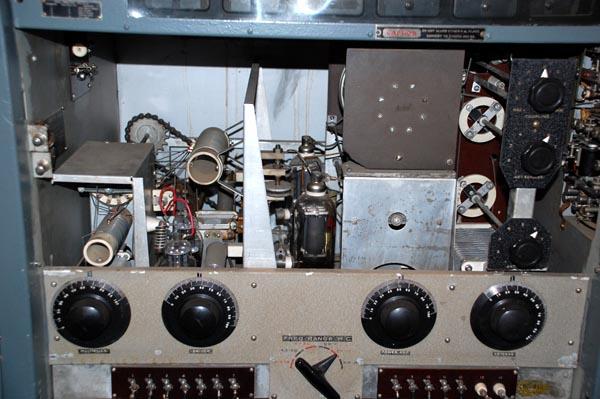
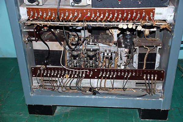
form of an AC buzz. Many Radiomen tuned the PV-500 HM2's by watching the power amplifier tubes through the front panel window. When the plate was cherry red but not white, the final stage was considered to be tuned. As an additional tuning aid, a small fluorescent bulb was taped to the antenna feed line and the final amplifier would be tuned for maximum brightness. On some PV-500's, the front bottom left power supply cover panel can be found somewhat dented. This was normal and was caused by having to kick it there in order to ensure that the power supply interlock engaged".

THE PV-500 AND ITS VARIANTS

PV-500 H - Basic model,  2.2 to 14 MHz coverage with 500 watts input.

This model was unlike its follow-on variants which had external controls to tune the multiplier, driver and RF stages. In the H model, the tuning for the multiplier, driver and RF output stages could be preset for each of 4 predetermined frequencies.

pv500_rcmp_radio_room.jpg
Taken in 1950, here is some of the equipment which could be found in the radio room of an  RCMP patrol vessel.  From left to right: Ben Colp, Bob Bell and Irwin Beatty. Behind Bob Bell is a PV-500H. It is believed that the cut out  holes in the front panel were an RCMP modification to facilitate the adjustment of the PV500 preset tuning and make it  more "frequency agile". (Photo courtesy of Staff Sergeant Ben Colp, R.C.M.P. Marine Division submitted by Spud Roscoe) 

 
pv500h_cutout_closeup.jpg
Close up view of the front panel holes. 
 
pv500h_original.jpg pv500h_internal_view.jpg
PV-500H with single piece cover for the RF deck.  PV-500H with all front covers removed. 
(Images courtesy Canadian Marconi)

The front panel switch has four positions.  It rotates all the variable capacitors in the multiplier, driver and RF output stages.  It is presumed that the all the stages have been pretuned correctly with “movable fingers”, the term Marconi uses. The operator switches the desired frequency using the VFO or crystal selector , then moves the big switch on the front panel to the same position. All the circuits  are now tuned. That’s all it takes to change frequencies .  An extract from the PV500H/L manual describes the operation

pv500h_topview1.jpg
Top view of RF deck. (Image courtesy Canadian Marconi)

 
pv500h_topview2.jpg
This view of the RF shows the wavechanger wheel and locking lever.(Image courtesy Canadian Marconi)
PV-500 HM -   3 to 19 MHz coverage with 500 watts input.
pv500hm_controls.jpg
PV-500 HM controls. (Image courtesy Canadian Marconi)

 
pv500hm_rfunit.jpg
PV-500 HM RF unit. The 810 tubes (V9, V10) are right on the centerline of the image. (Image courtesy Canadian Marconi)

 
A summary schematic of the PV-500HM is available here.
PV-500 HM2 - The upper frequency range was extended from 19 to 28 MHz and the keying was stabilized.  Although not mentioned in any manual, the 'HM2  originally installed aboard the destroyer HMCS HAIDA had been modified to operate with a Frequency Shift Keyer at some point in time. It is believed this modification was carried forward to the HM3. When comparing the H versus HM2 schematics , it appears that the tone oscillator was removed in the HM2 modification thus no more ICW mode.
/pv500hm2_07_2021.jpg
PV500-HM2 Note the new positions of the placards.  PV500-HM2. This rare view shows the RF protection screen around the feed through insulator near the top, The dummy load consisted of four 150 watt light bulbs .  Initially, the PV-500 HM2 was attached to bare copper transmission line but later on,  the RCN retrofitted the transmitter with coaxial connectors suitable for use with RG-18/U.  (Image courtesy RCN)
PV-500 HM3 -  Since there was no drive level control provided in the PV-500 HM2, there was excessive drive at lower frequencies and insufficient drive at high frequencies. Multiplier stages had to be detuned to obtain the desired drive levels. To reduce chirp on CW, the multiplier stages were keyed while the oscillator was held on for the duration of a 'word'. This reduced chirp to the first letter of each word sent and permitted the use of break-in operation. In the PV-500 HM3, there were design changes to overcome these deficiencies. A driver stage and drive level control were added.
 
pv500hm3.jpg
PV500 HM3   (Canadian Marconi photo) 
PV500 HM4 - There was a large power loss in the trunking to the antenna, so the antenna tuner wasremoved from the transmitter and was re-designed for remote operation near the antenna feed point.  (No photo of the HM4 variant available at this time)
i/pv500hm_settings placard_01.jpg
Quick tune chart for PV500HM. This chart looks like its been handcrafted rather than being commercially printed. Click on image to enlarge. DESG likely means Designator, otherwise called a radio channel identifier. ( Photo by Jerry Proc) 
PV500HM2_quick_tune placard.jpg
Quick tune chart for PV50 -HM2. Click on image to enlarge .( Photo by Meir Ben-Dro  WF2U)
pv500hm2_placard_DSC_0024a.jpg
Another quick tune chart for a PV500-HM2. Click on image to enlarge. 
/pv500hm2_rf_chart_DSC_0039a.jpg
This is the RF Generator chart for bands A, C and E on a PV500-HM2  Click on image to enlarge.
pv500hm2_rf_chart
This is the RF Generator chart for bands B, D, F and G. on a PV500-HM2  Click on image to enlarge.
pv500_dual_nameplates.jpg
When a Canadian Marconi PV500 HM was converted to a PV500 HM2, Canadian Aviation Electronics affixed one of their own nameplates to the front panel. (Image provided by Meir Ben-Dror)
DETAILED SPECIFICATIONS
 
Marconi designators: Model PV-500HM -  #96395 and 109-925
                                     No designators for HM2/3/4 since these are believed to be field
                                     modifications,

Frequency Range: Model H      -  2.2 to 14 MHz
                                 Model HM   -  3 to 19 MHz
                                 Model HM2 -  3 to 28 MHz
                                 Model HM3 - Same as HM2
                                 Model HM4 - Same as HM2

Power Input:  Model H     -  500 watts
                       Model HM  -  500 watts
                       Model HM2 - 500 watts from 3 to 19 MHz; 300 watts from 19 to 28 MHz.
                       Model HM3 - Same as HM2
                       Model HM4 - Same as HM2

MCW audio tones available - 400 , 700 and 1,000 Hz
Keying speeds: Up to 100 wpm without break-in; 30 wpm using  break-in
Antenna Loading: 5 to 200 ohms resistive.
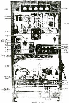
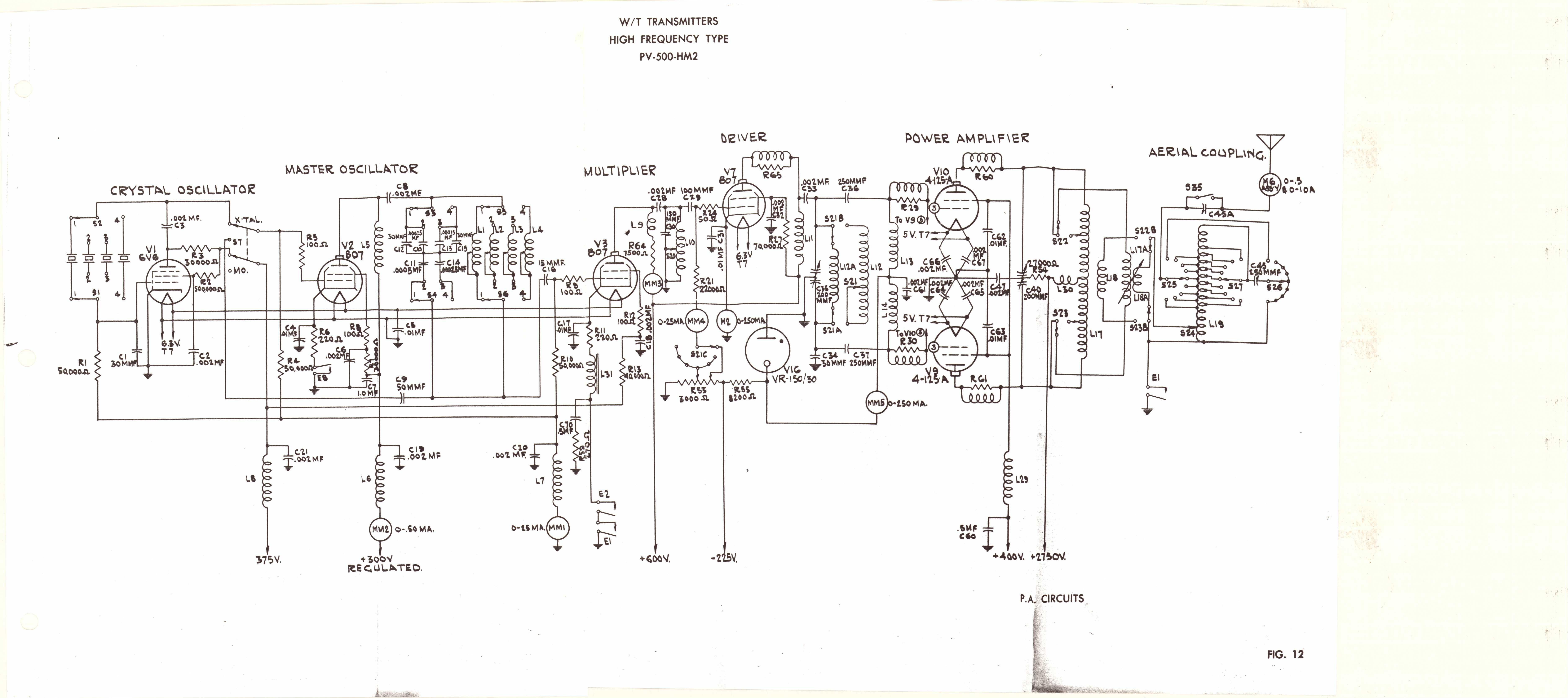
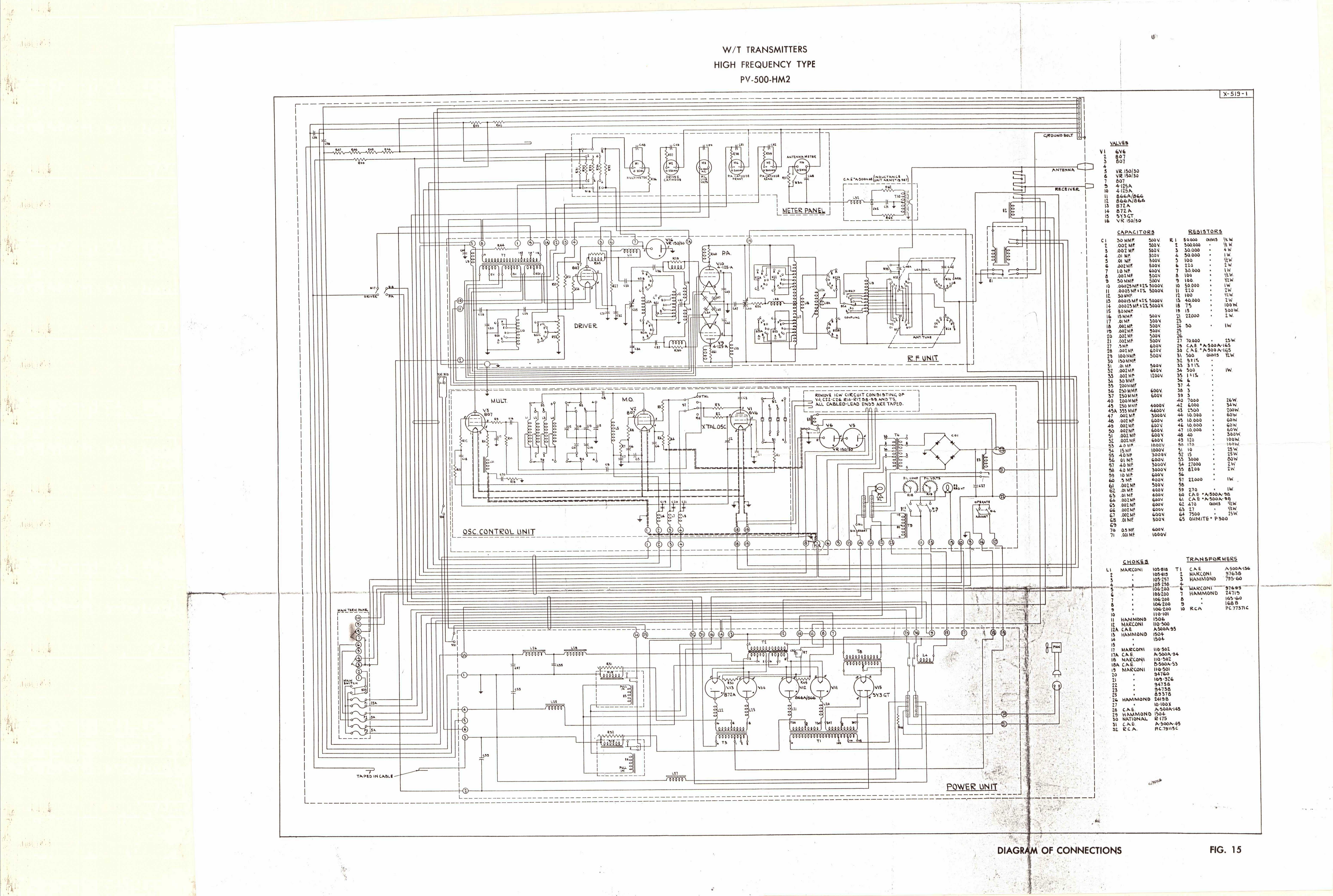
Tube lineup: 2 x 810 for HM (or 2 x 4-125A for HM2/3/4), 3 x 807, 1 x 6V6, 3 x VR150-30, 2 x 866A, 2 x 872A, 1 x 5Y3
Transmitter control: Full break-in system
Assembly reference number: PV-500HM   # 86790
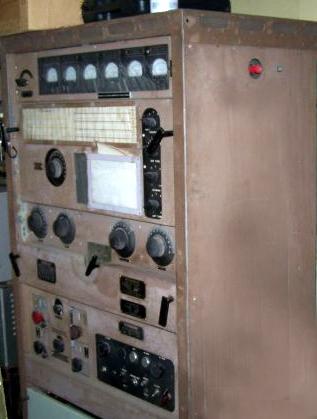
Colours: Tan, crackle paint finish confirmed. Not sure what other colours were offered.

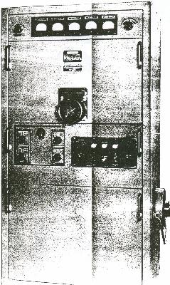
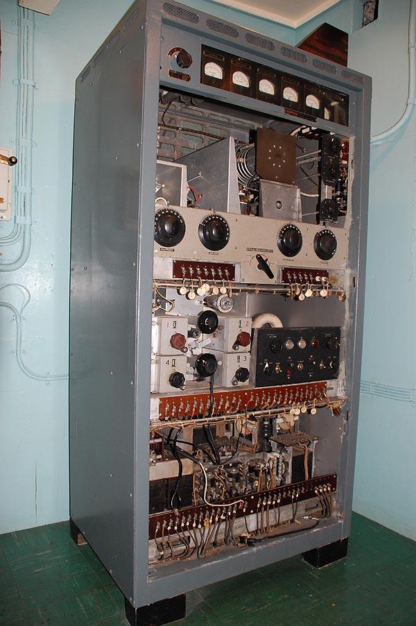
Transmitter dimensions: Height 66 in , Width 35.25  in, Depth 23 in.
Transmitter weight: Up to 695 pounds depending on variant.

Rotary Converter dimensions: Height 16.25 in, Length 22.25 in, Width 14"
Power Required: 120 volts at 60 Hz. 1,800 watts to 2000 watts depending on variant. If only 110VDC is available, then the rotary converter must be used.
Rotary Converter weight: 300 pounds.
Power Consumption on rotary input : (Key up) 14.5 amps at 110 VDC
                                                               (Key down) 26 amps at 110 VDC
                                                               (Standby) 11 amps at 110 VDC

Applicable manuals: BRCN 5423 for PV500-HM2
                                     Marconi 96395 for PV500-HM

If the ambient temperature is too low, an  additional 4 amps at 110 VDC is consumed by the power supply heaters.

CLOSE-UP VIEWS OF THE PV-500HM
pv500_hm_internal1.jpg
General view of the PV-500 HM with protective panels removed. Weighing up to 695 pounds, the only way to easily move this transmitter is to disassemble it into four pieces: cabinet, RF unit; oscillator unit and power supply.  Note the RG-18 (7/8 inch dia)  coax connecting to the right side of the transmitter. This transmitter has only been flashed up several times since 1994. It sure gets hot in HMCS HAIDA's Radio 2 when the unit is powered up and the room ventilation is not running. (Photo by Jerry Proc)
pv500_hm_internal3.jpg
RF Unit: This assembly contained the driver stage plus two 810 triodes in push-pull configuration in the RF output stage. Power input is 500 watts. Since this assembly has a tan coloured panel, it is believed that it came from another transmitter. Note the sprocket and chain drive at the back left.  (Photo by Jerry Proc)
pv500_hm_internal4.jpg
Oscillator and Control Deck: At the left side are four, selectable master oscillators which could be preset to specific frequencies. In between are sockets for four crystals. Stages include: Crystal oscillator, Master oscillator, Multiplier and ICW tone oscillator.   At the right is the control panel for the entire transmitter. (Photo by Jerry Proc)
pv500_hm_internal5.jpg
Power Supply: Provides all DC voltages to the transmitter using 866 and 872 rectifier tubes. It is by far, the heaviest assembly in the transmitter. All the panels engage gate switches (interlocks) which drop power if any one of them is removed. It is then necessary to use the override function of the gate switch to restore power.  (Photo by Jerry Proc)


pv500_tan.jpg
PV-500 in its original tan livery. This example belongs to Meir Ben-Dror, WF2U. (Photo by Meir Ben-Dror)

DOCUMENTATION

PV 500 H and PV500L Combination Manual

This PV500 HM schematic has been  tiled into two parts . (Schematics  provided by Jason Ingraham)
PV 500HM main schematic - Part 1
PV 500HM main schematic - Part 2

PV500 HM2 Service Manual
PV500 HM2 Simplified Schenatic (full size; JPG format.. Prints to 24 inch wide paper)
PV500 HM2 Complete schematic (full size; JPG format.. Prints to 24 inch wide paper) 

PV500 HM3 Service Manual  (Reference: BRCN 5423A)


pv500_landh_fit_s.jpg This interconnection diagram shows the PV-500H and PV500L transmitters and a SMR-3 receiver  co-located in the same radio office aboard a ship. Circa 1943.  (Image courtesy Canadian Marconi) 
The following standard RCN crystal frequencies were available for the PV500 series transmitter.

Contributors and Credits:

1) Meir Ben-Dror, WF2U <wf2u(at)ws19ops.com>
2) Keith Kennedy, <a4a88300(a)telus.net>
3) PV500HM Manual
4) Jason Ingrahamthe_doctor31@hotmail.com>

Back to Equipment Listing


Feb 1/22