 |
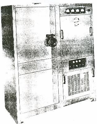
| PV-500L. (Photo courtesy Canadian Marconi) |
PV-500L Low Frequency Transmitter (RCN) and GT-14 (RCAF) The PV-500L transmitter was a CW/ICW (MCW) unit operating in the frequency range of 100 to 500 KHz. It had a rated power input of 500 watts and frequency control was by master oscillator (MO) only. There were four switch selectable MO's in total and they were preset to the four most popular operating frequencies. In ICW mode, the operator could select frequencies of 400, 700 or 1,000 Hz.
One characteristic feature of the PV-500L was it's large footprint. Since inductors and capacitors that operate in the low frequency band are rather large in physical size, they were not enclosed in the same cabinet as the PV500 proper. Instead, they were mounted external to the transmitter and shielded with a wire cage. Entry to the cage was interlocked and power would be disconnected if the door was opened. The recommended transmission line was 3/8 or 1/2 inch copper tube.
For shipborne use, Canadian Marconi suggested the use of a 4 wire flattop, approximately 54 feet long and at least 35 foot above the deck. The RCN fitted this transmitter on numerous ships during WWII.
|
| PV-500L. (Photo courtesy Canadian Marconi) |
 |
|
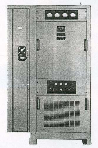
| PV-500LM or LM1 variant shown without protective screening. (Photo courtesy Canadian Marconi). |
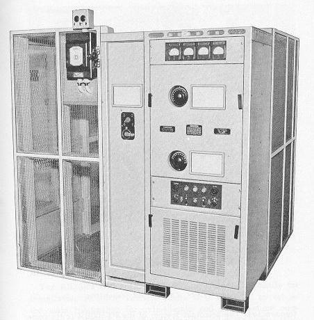 |
| PV-500LM2 or LM3 variant. When shipping, the transmitter can be broken down into two separate pieces. (Photo courtesy RCN) |
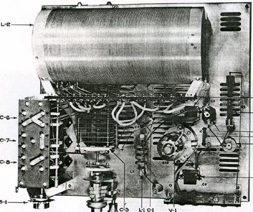 |
| PV-500L and LM1 oscillator deck. Note the size of the coil in comparison to the oscillator tube. (Photo courtesy Canadian Marconi) |
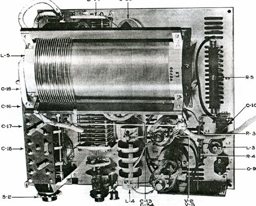 |
| PV-500L and LM1 power amplifier deck. (Photo courtesy Canadian Marconi) |
SPECIFICATIONS:Frequency range: 100 to 500 KHz.
Modes CW or ICW
Power output varies : 500 watts RF (upper end of range) down to 300 watts RF (lower end of range)
Antenna Loading: 10 to 12 ohms resistive.
Tube Lineup: 3 x 810, 2 x 872A, 1 x 807, 1 x 5Z3
RF anode voltage : 2000 volts.
Marconi designator: # 96385
Variants: PV-500LM1, 2 and 3
Confirmed Colour: Navy blue. May be others.Dimensions: Height 66 in , Width 52.25 in, Depth 26 in.
Weight: 865 lbs.
Control: Full break-in system
Primary power: 115 VAC, 60 Hz. If not available , then a 110/or 220 VDC rotary converter must be used.Rotary Converter dimensions: Height 16.25 in, Length 22.25 in, Width 14"
Rotary Converter weight: 300 pounds.
Power Consumption on rotary input : (Standby) 11 amps at 110 VDC
(Key up) 14.5 amps at 110 VDC
(Key down) 26 amps at 110 VDCIf the ambient temperature is too low, an additional 4 amps at 110 VDC is consumed by the power supply heaters.
PV-500L VARIANTS PV-500LM1
In the PV500-LM1, type 110-925, the filament compensator circuit is arranged to use a General Radio type 30-B Variac in place of the filament compensating resistor R34. This changes causes the transmitter to bear a different type number.
PV-500LM2
The mechanical feature that was used to reset the variable condensers C3 and C14 in the PV-500LM and LM1 has been removed on the LM2 and LM3 variants. In place of the mechanical feature, these condensers are now coupled to the vernier dials mounted on the Master Oscillator the PA units. The front cover has been modified to permit them to be operated without the removal of the cover.
Secondly, the antenna loading coil has been modified to provide increased flexibility of operation by providing additional taps on the lower section of the coil used for fine tuning.PV-500LM3
This transmitter is electrically identical to the LM2 but in addition, it has a full-configuration protective cage for use in shore based installations where it would not be possible to use a ship's bulkhead to complete the screening of the antenna coil.
 |
This
schematic shows a suggested fitting when both the PV-500 high and low frequency
transmitters and SMR-3 receiver are fitted into the same radio office aboard
a ship. (Image courtesy Canadian Marconi)
Bill Rogers of Delta
BC used a PV500L at the RC Signals station at Ennadai Lake, NWT in 1951/52.
It was used on 212 KHz mostly during the day in order to key the station's
identifier so aircraft could home in on it.
|
GT-14
The GT-14 was the RCAF version of the PV500L.RCAF Ref: 10D/4213 C.A.P.(Canadian Air Publication) 63.14
Marconi manual: #483
Range : 100 to 500 kHz
Power : 500 watts
Modes: CW and ICW
Frequency Control: Four preset frequencies.
Remote Control : Can be remotely controlled over land lines not exceeding 10 miles in length.
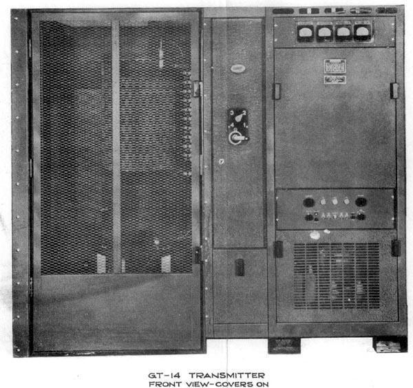 |
| GT-14 (Photo courtesy Canadian Marconi, via Bruce MacMillan) |
Contributors and Credits:1) PV500L Manual
2) Bill Rogers <wlrogers(at)telus.net>
3) Bruce MacMillan <radio(at)telus.net>
Aug 8/21