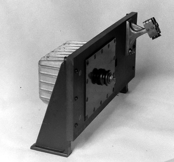
Rotary Spark Gap
Transmitter #1
This shipboard transmitter,
built by Marconi Wireless Telegraph Company of Canada (MWTCC), has
no model so its being assigned designator Rotary Spark Gap Transmitter
#1. An article written about it, refers to this transmitter as the " All
Canadian Ship Set".
SPECIFICATIONS
Frequency range:
Three wave - 300, 600 or 800 metres wavelength
Type: Rotary Spark
Gap transmitter
Power output: Low,
medium and full .
Vintage: This
transmitter is described in the April 1922 issue of Canadian Wireless Magaziine.
The full article is here.
EARLY TRANSMITTERS
IN GENERAL
The Canadian Wireless
article said that this transmitter was new when, in fact, it was
already obsolete in 1922. Tube transmitters transmitted twice as far and
with a much narrower band width. By international agreement, spark transmission
was to be outlawed starting in 1930 but the transition from spark spanned
several years.
At the International
Radio Telegraph Convention of Washington, held in 1927, an agreement was
reached in the following general terms:
(a) The use of damped
wave trains (Type B waves) employing frequencies below 375 kc/s were forbidden
from 1st January, 1930, onwards.
(b) No new spark
transmitting installation could be fitted in a land or fixed station or
in shore station from the 1st January, 1935.
(c) No new installations
for the emission of spark wave trains could be fitted in ships or in aircraft
from 1st January, 1930. The only exception to this was the situation where
the transmitters used 300 watts or less of power as measured at the input
of the supply transformer.
(d) Use of spark
transmission on all frequencies were forbidden from the 1st January, 1940,
except for ship installations. In those cases, the transmitter, would have
to meet the power criteria of article (c). In the Royal Navy, by the end
of the 1930s, a radio installation employed a spark gap transmitter for
emergency purposes only under the following conditions:
(e) A spark attachment,
for use as a stand-by transmitter in the event of a complete breakdown
of the tubes or essential components of the main tube transmitter(s).
(f) An emergency
coil, designed for use when power from the ship's mains also fails. It
consisted of an induction coil and an associated oscillatory circuit. It
derived its power supply entirely from batteries. These emergency transmitters,
while rarely ever used, were fitted only to provide a last line of "defence".
Some ship owners
converted spark transmitters to tubes. Unfortunately the article
does not tell us the model name or number , power, how many were sold ,
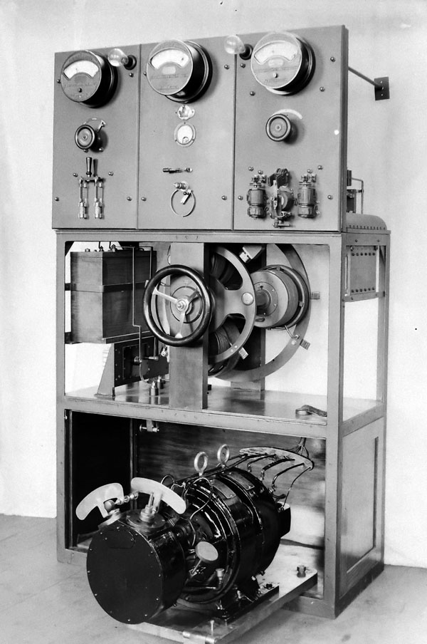
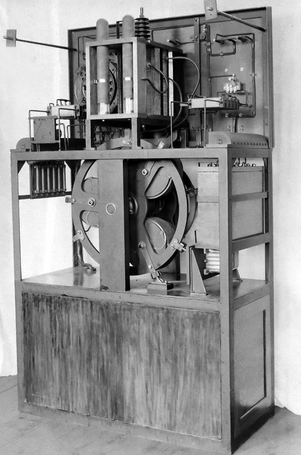
or name of the ship in the photo. Numerous photos of this transmitter and
its components are in the Marconi Collection in the National Archives.
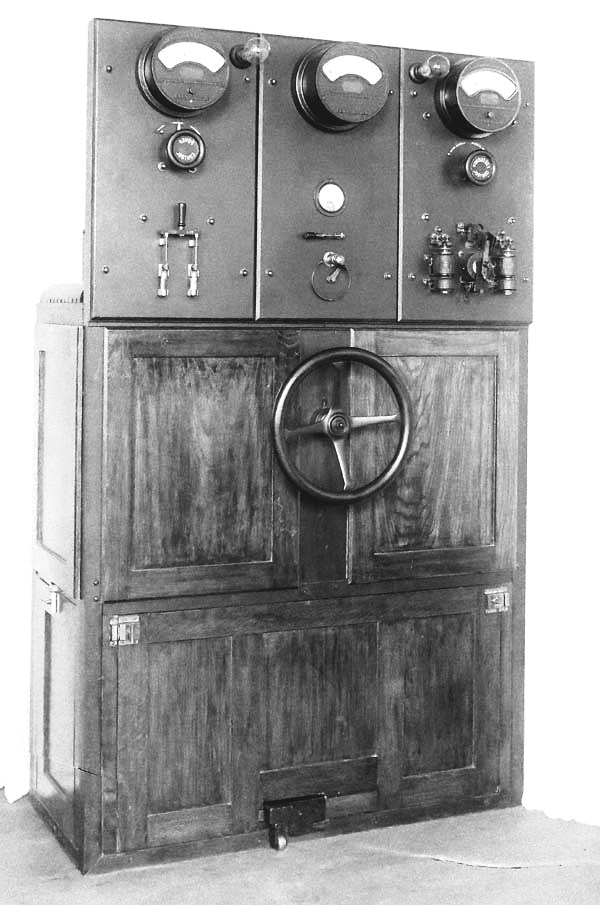
This was probably the last of the ship spark transmitters.
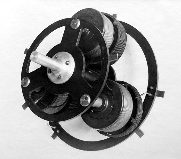
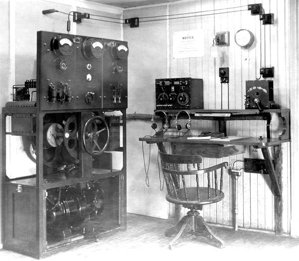 The rotary spark gap transmitter installation aboard a ship. The big wheel
was used to change the wavelength (LAC photo)
The rotary spark gap transmitter installation aboard a ship. The big wheel
was used to change the wavelength (LAC photo) 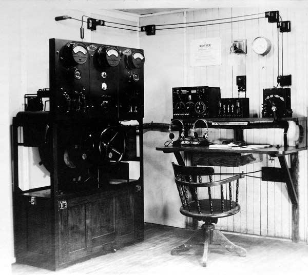
_100_3234.jpg)