 |
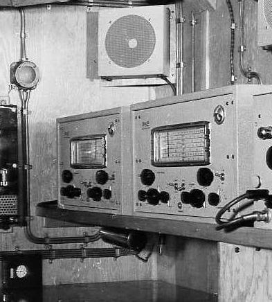
| A pair of SMR-3 receivers fitted in the radio room of HMCS Prince Rupert, 1942. (Public Archives Canada Photo HS-0262-1 submitted by Spud Roscoe) |
SMR-3 MARINE RECEIVER
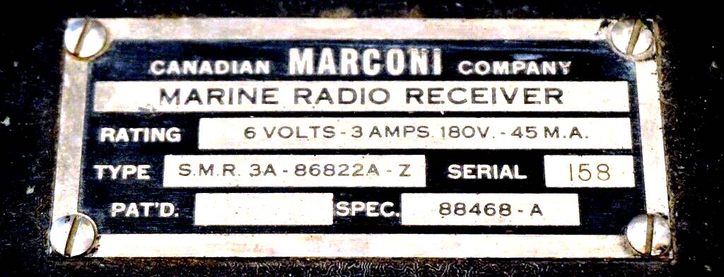
Type: Marine Radio Receiver #86822A
Tube count: 9
Manual: #88467 Inst. 350
Circa: February 1941
Specification: 88468-A
Frequency range:Band 1 - 15 to 30 MHz
Band 2 - 6.5 to 15 MHz
Band 3 - 3.3 to 7.5 MHz
Band 4 -1.5 ro 3,5 MHz
Band 5 - 250 to 515 KHz
Band 6 - 97 to 240 KHZ.IF: 575 KHz
Dimensions: 20" W x 11 7/8" H x 11 7/8" D.
Weight: 60 pounds not including power supply.
Power supply: Type VP-1 external #85025.
6 volts@3 amps and 180 VDC @ 45 ma output. Circa 1939.
Colours (known): Olive green, Green and Tan crackle finishes. The letter suffix in the stock code may indicate case colour (unconfirmed).
Variants : SMR-3 and SMR-3A
Comment: 1) Used extensively by the Royal Canadian Navy during WWII.
2) Thge VP1 power supply was origianlly designed for the Marconi LFR-7
|
| A pair of SMR-3 receivers fitted in the radio room of HMCS Prince Rupert, 1942. (Public Archives Canada Photo HS-0262-1 submitted by Spud Roscoe) |
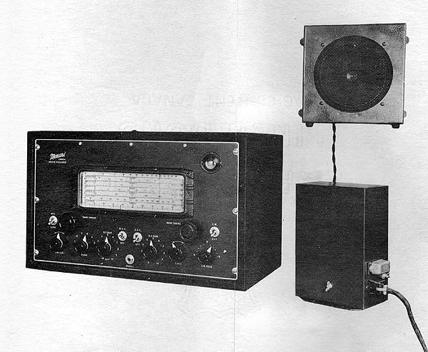 |
| SMR-3 with VP-1 power supply and original factory speaker. (Photo courtesy Canadian Marconi) |
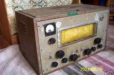
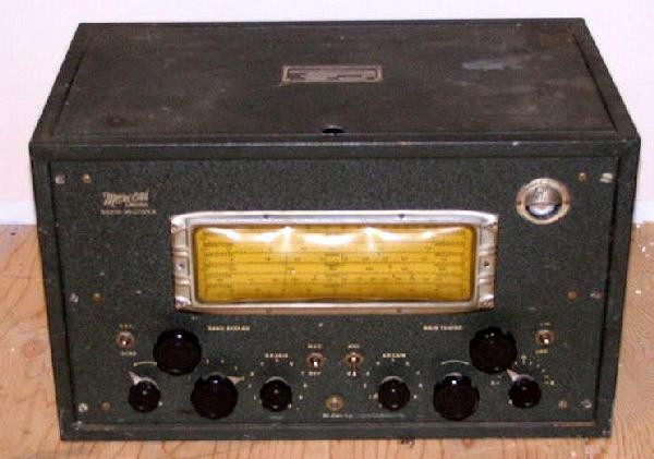
This is SMR-3A S/N 102. SMR-3 s/n 191 . Click on image to enlatge. (Photo by Serge Haineault}
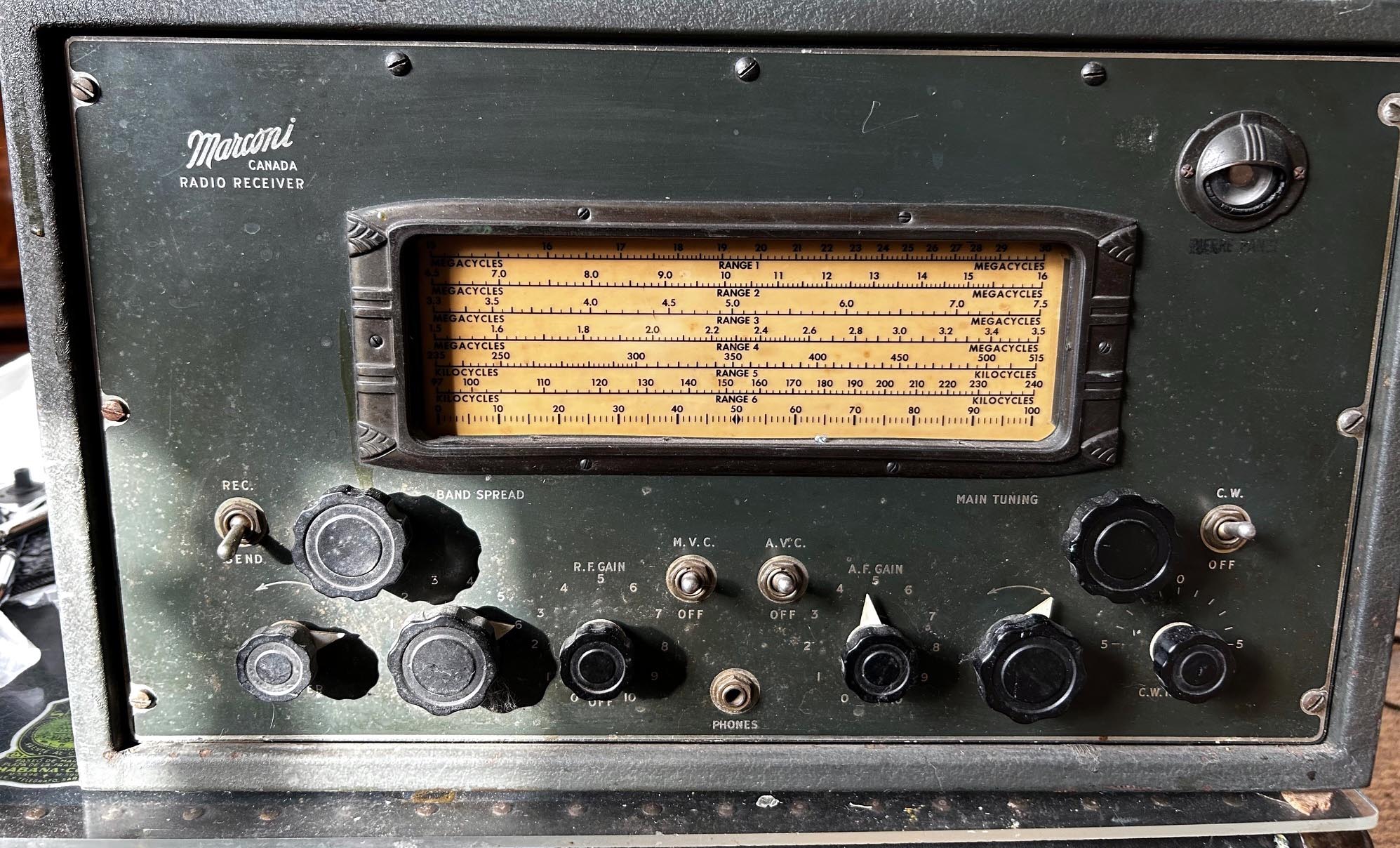
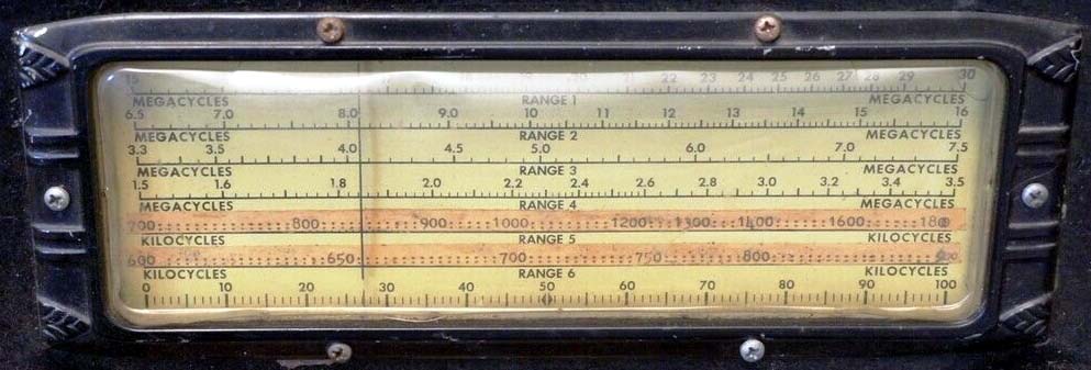
SMR-3 - Closeup of dial. This example has been modified so bands 5 and 6 receive the broadcast band instead of the original LF bands,. (Photo via E-bay) SMR-3 nameplate
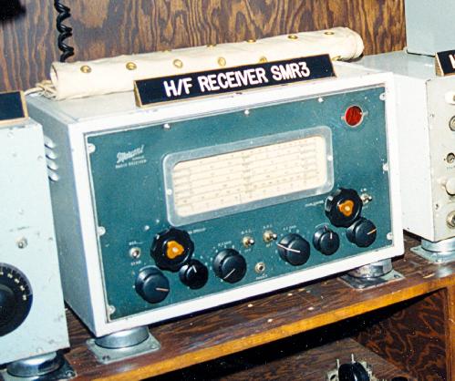
SMR-3 installation aboard the restored corvette HMCS Sackville. The magic eye tube and bezel is missing and the knobs are not original in this example. (Photo by Jerry Proc)
 |
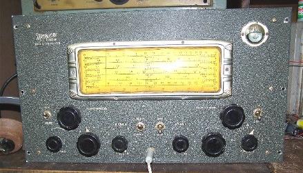
| This SMR-3A S/N 126, owned by Meir WF2U, had been previously modified with the additional of a non-original panel meter. It also illustrates the front panel colour. (Photo by Meir Ben-Dror, WF2U) |
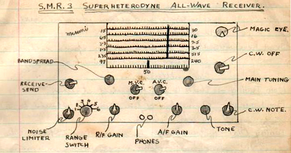 |
| This hand drawn sketch came from a WWII era radio operator in training. (Submitter unknown) |
 |
| SMR-3A S/N 102 has been energized successfully as evidenced by the green glow of the magic eye tube. (Photo by Meir Ben-Dror, WF2U) |
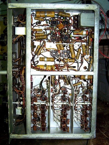 |
| SMR3A - Bottom view of chassis. (Photo by Meir Ben-Dror, WF2U) |
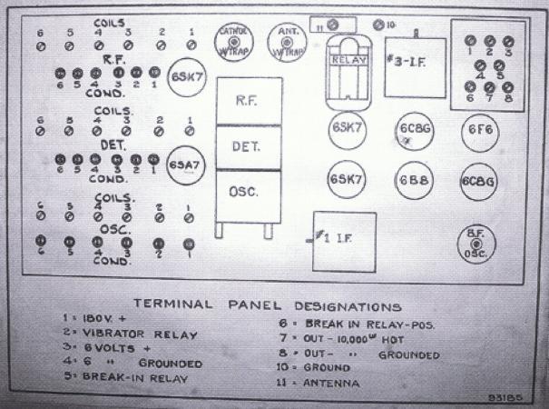 |
| This is the paper label which is affixed to the inside of the SMR-3 receiver lid. Click here to download a PDF file of the actual size label. This has been created by Meir Ben-Dror, WF2U. (Photo by Meir, WF2U) |
SMR-3 Manual Courtesy Tom Brent
SMR-3 schematic from manual
SMR-3 schematic redrawn by Gord Skiffington VE1AJF
Contributors and Credits:1) Meir Ben-Dror, WF2U Landrum, SC <wf2u(at)ws19ops.com>
2) Gord Skiffington <skiffing(at)nbnet.nb.ca>
3) http://www.nzvrs.pl.net/aaa/ifreqs.htm
4) Spud Roscoe <spudroscoe(at)eastlink.ca>
5) Tom Brent <tgb(at)telus.net>
6) Canadian Marconi, Montreal
Dec 19/25