 |
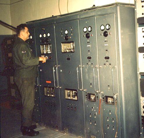
| TH-41 (Photo courtesy Pinetree Line) |
TH-41 Transmitter The TH-41-B transmitter, is a high-power, transmitter for ground fixed station used in long distance point-to-point communication. It consists of nine large cabinets containing the following: rectifier power supply, modulator, LF RF unit, four HF RF units, two RF exciter units and one separate remote control unit. Each RF unit con be operated on 10 preset channels (either crystal or master oscillator frequency controlled), except the LF unit which uses master oscillator frequency control only.
Three transmitting units can be operated simultaneously on either CW or FSK. When voice is used, only two units may be operated at a time (one unit modulated and the other on CW or FSK.
Complete remote control of all functions is provided by Master Remote Control Unit 141-398 from distances up to 5 miles over four pairs of standard telephone lines.The transmitter RF units are designed to operate into a 600-ohm balanced or unbalanced transmission line; however, on L type matching section is included in the HF units to provide on impedance matching range of 70 to 2,500 ohms. The LF unit uses a T-type matching section for 72-ohm coaxial cable RG-34/U, or equivalent.
SPECIFICATIONS
Frequency range: LF - 80 KHz to 200 KHz, single channel, master oscillator (MO) frequency control.
HF (TH-41) - 2 to 28 MHz; overall . 10 preset channels per RF unit. Either MO or crystal control may be used.
HF(TH41B) - 5 to 13 MHz for one of the HF RF units.The Royal Canadian Navy used the TH-41 transmitter in its shore stations. In 1963, these crystal frequencies were available for the transmiiter.
Power Output : 5,000 watts
Modes: CW, FSK and AM voice
Power requirements : 40.5 kva, 208/220 v, 3 phase, 60 Hz.
250 w 115 V SIngle phase 60 Hz when MO oven heaters are used.
150 additional watts when remote control equipment is used.Dimensions: 125 in wide x 81 in high x 37.5 in deep.
Weight: 10,000 pounds. Ships in 15 packages.
Circa: June 1952
|
| TH-41 (Photo courtesy Pinetree Line) |
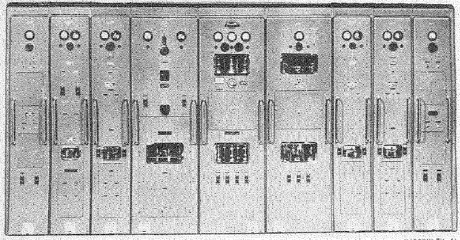 |
| The complete TH-41 (Photo courtesy JPtronics Org) |
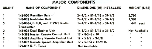 |
| TH-41 major components (Data courtesy JPtronics Org) |
OTHER PART NUMBERSThe 5-13 MHz RF unit is part number 148-006B with driver 148-054B.
There is a 2 to 5 RF ubit 148-006A with driver 148-054A .
There is a 13 to 20 MHz RF ubit t48-006C with driver 148-054C .
All three of the above use 4 x 813 tubes in the driver, circa 1951.
There is also a HF unit 148-007D with driver 148-060 which used 4x4D22 tubes in the driver, circa 1951.There is also a LF unit TH41A LF RF unit 112-973, Driver 116-937. The driver uses 4 x 4-250s, circa 1949.
The modulator is 148-002 and the power supply is 148-000.
There is an antenna tuning unit 129-837.
Drivers in units 148-054 have taped coils with colour codes on the taps which probably allow any to be modified to
the A, B or C type. The 813 coils are very different and specific to frequency.
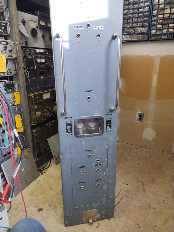 |
| TH-41B RF cabinet. |
| TH-41B Meter detail |
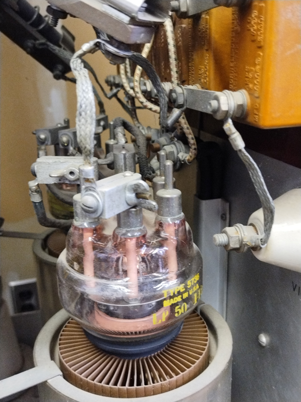 |
| TH-41B RF deck, Detailed view |
 |
| TH-41B RF deck, Detailed view |
 |
| TH-41B RF deck, Detailed view |
| TH-41B nameplate. |
| All TH-41B photos in this table by Jim Fleming VE3PBJ |
Contributors and Credits1) Pinetree Line http://www.pinetreeline.org/photos/stephe/steph199.jpg
2) JPtronics http://jptronics.org/radios/Military/JANAP161/an.frt/an.frt-type.th-41-b.pdf
3) Jim Flening VE3PBJ
June 20/25