 |
A lineage for thermionic tubes 1883 to 1934. Click on thumbnail to enlarge. ( Edited by Kent Leech) |
TUBES This document is intended to showcase a small cross section of tubes used in early radio equipment.
|
A lineage for thermionic tubes 1883 to 1934. Click on thumbnail to enlarge. ( Edited by Kent Leech) |
| Early radios used 00, . 01A and also Cunningham 300 series tubes. Data for these types is provided here. | |
 |
Click
on thumbnail to enlarge. This page for the 00 and 01 tubes is from
the 1937 RCA tube manual (Provided by Lewis Bodkin)
|
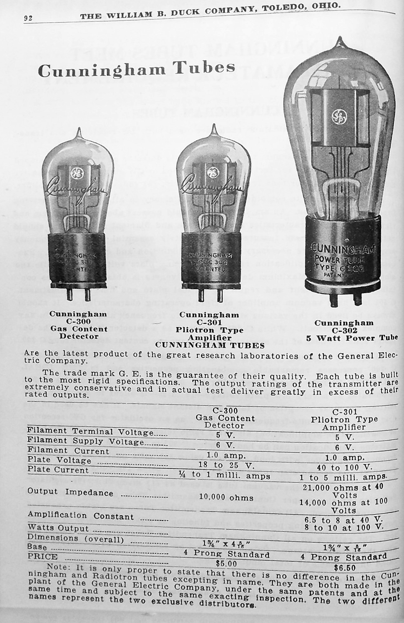 |
The
letter "C" and the three hundred series was for the Cunningham brand.
Click on thumbnail to enlarge. From the 1921 Duck catalog.
Both 200 and 300 as a series number were later dropped.. The Cunningham 301 was the same as a CGE 201 (Provided by Lewis Bodkin) |
 |
| Marconi
'Q' valve (See credit #2)
Introduced in 1916, this triode had widely positioned leads to minimize inter-electrode capacitance. It was a high impedance tube, used primarily as a detector. Like all early Marconi valves, it was made originally by Edison Swan but after 1919 by MOV. Filament: 6 VDC @
0.4 amps
|
 |
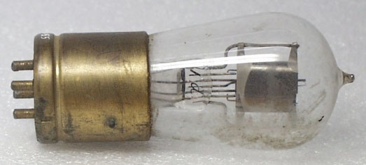
| Marconi
'V24' Tube. (See credit #2)
This tube, a directly heated triode, was a development of the 'R' type aimed at improving high frequency performance. The V24 was introduced in 1916 by Marconi UK and was used as an RF amplifier. To reduce parasitic capacitances the leads of the valve were separated as much as possible. For replacement purposes SPECS: Filament -
5 volts at 0.75 Amps
Although MWTC used Q valves and V 24 valves in their receivers and amplifiers before March 1922, it is unlikely that any of these valves were made in Canada. For replacement purposes, the V24 valves were still being made as late as 1937. |
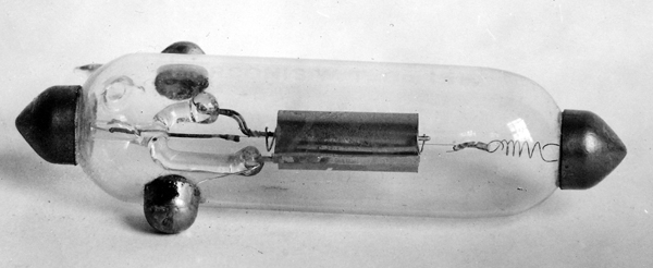 |
| A more detailed view of the V24 tube. So far, there is no evidence to show that any of these tubes were manufactured in Canada earlier than the latter part of 1921 according to Radio Trade Builder magazine ,December 1934. (Photo by Lewis Bodlin) |
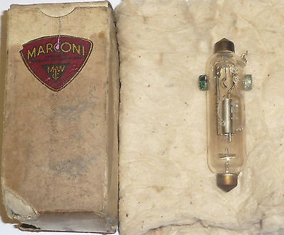 |
| This NOS (New Old Stock) V24 valve comes in its original box (Via E-bay, UK) |
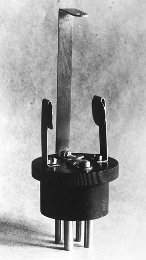 |
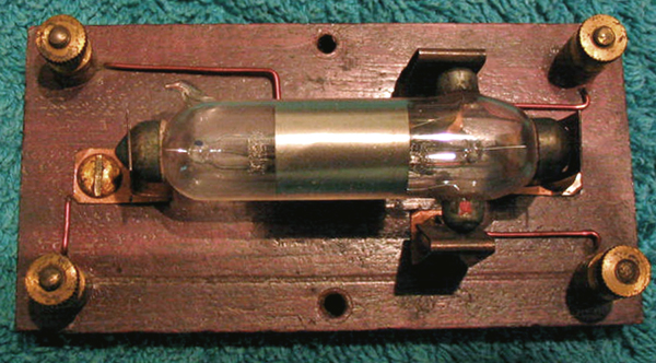
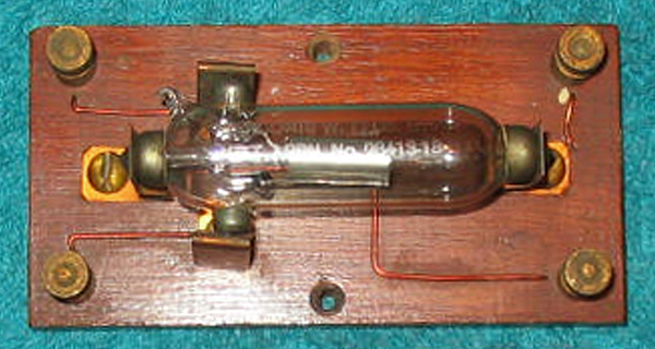
| This is an adapter for socketless tubes such as the V24. (Image provided by Lewis Bodkin) |
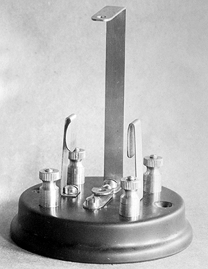 |
| This adapter for socketless tubes would have been used in radios that employed the breadboard technique of fabrication. Image provided by Lewis Bodkin) |
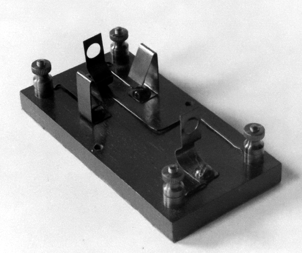 |
| This adapter facilitates the mounting of a socketless tube in a horizontal position. (Image provided by Lewis Bodkin) |
 |
| Type: UV-201 receiving
triode.
Filament - Pure tungsten. 5 volts @ 1 amp. Plate Voltage 135 VDC max Amplification factor: 8 Vintage: 1922 Comment: The UV prefix meant Universal Valve base; one having four short pins. Introduced in 1922, the UV201A uses a thoriated tungsten filament which only draws 250 ma. (Photo by Louis Bodkin) Manufacturing of the UV 201A began at the earliest in October 1922. By August 1923 it it became Marconi's most popular selling tube. In the UV designation,
U signified that it was an apparatus unit and V meant
In 1934, RCA , GE, and CGE renumbered tubes that they had made throughout the 1920s. The 200 series became two digit numbers. So 201-A became 01-A. Number 199 became 99. The 201 tube was no longer being made at that time. As well, the Cunningham brand tubes made by GE in USA were no longer being made. |
1930s or LATER
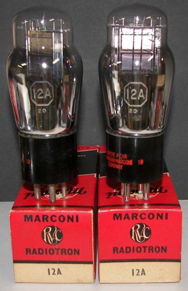 |
| Type 12A triode (Ebay photo) |
 |
| 1C21 Thryatron |
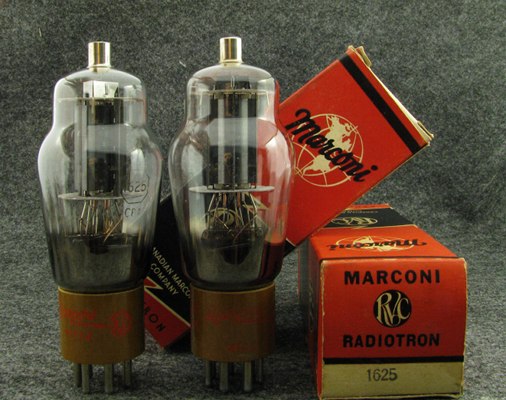 |
| 1625 beam power tetrode |
 |
| 832A transmitting tetrode |
 |
| 6SN7 dual triode |
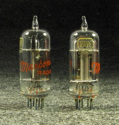 |
| 12AV6 Double diode and triode |
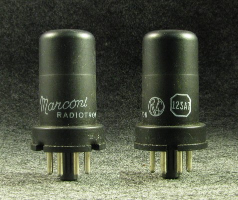 |
| 12SA7 - Single ended series example |
| All photos in this table by Pierre Lewis |
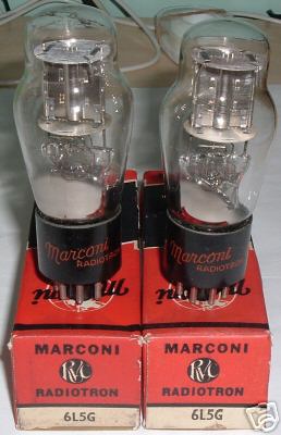 |
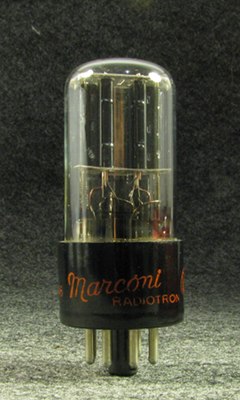
| 6L5G Power Triode Amplifier |
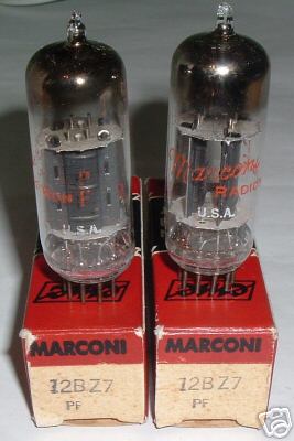 |
| 12BZ7 high-Mu twin triode |
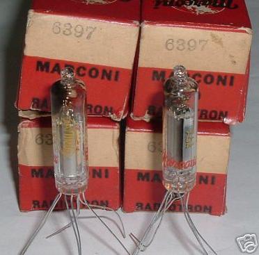 |
| 6397- Power Amplifier Pentode |
 |
| 6AF6 miniature octal, magic eye tube. |
|
|
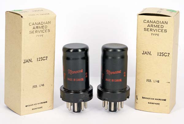 |
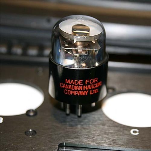
| This example of a 12SC7 tube, was built under contract and was common to all the Canadian Forces. The 12SC7 is a hi-Mu twin triode. (E-bay photo) |
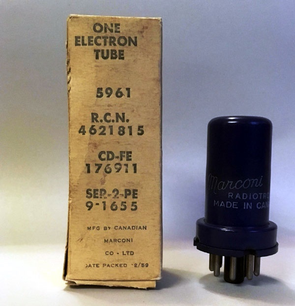 |
| This 5961 tube, packaged generically, was built specifically for the RCN in February 1959. (Photo by Tom Brent) |
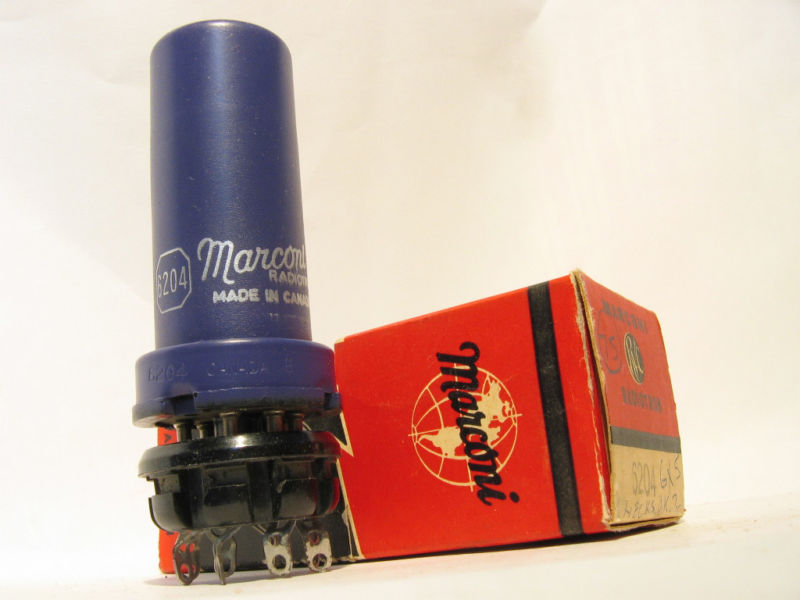 |
| This 6204 tube with
a blue finish was never registered, but it is a 6.3 volt, half wave rectifier
that is equivalent to one half of a type 6X5.
The 5961 tube, also painted blue is described as as "Canadian reliable 6SA7". Marconi made a 6006 tube whose finish was red. This is identified as a "ruggedized remote cutoff pentode (Canadian) version of the 6SG7". The 5961 and 6006 tubes mentioned above were referenced from : MIL-HDBK-213, "Electron Tubes Interchangeability Directory" published by the United States Department of Defense and dated November 02, 1959. |
 |
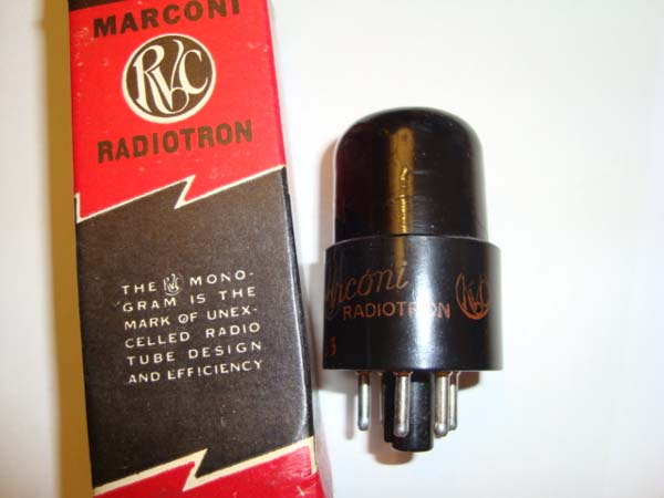
| Some
of the 8 pin octal tubes were applied with a metallized coating of some
sort which acted as a shield. This technique did not seem to catch
on in North America but was frequently found on European made tubes.
European tubes such as the type EF37, had a similar coating often painted
red.
In Canada, Rogers Majestic used the metalized coating on some tubes., It was usually black or grey in colour. |
 |
| This is a basing diagram for the 86M tube which shows the electrical connection from the metallic coating to pin 1 of the base. |
 |
| A more contemporary tube carton. (E-bay photo) |
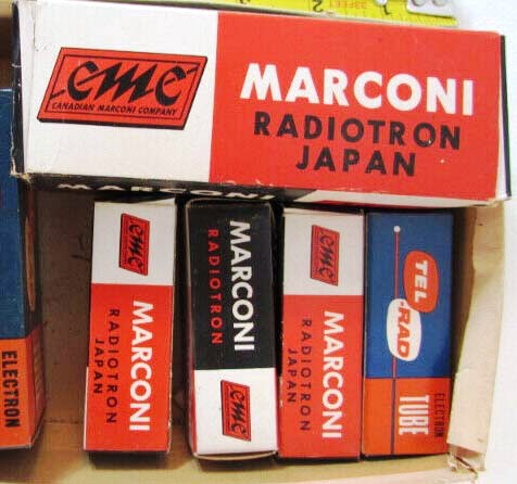 |
| The topmost tube carton is of interest because it was made for Canadian Marconi in Japan. (Image via Kijiji,ca) |
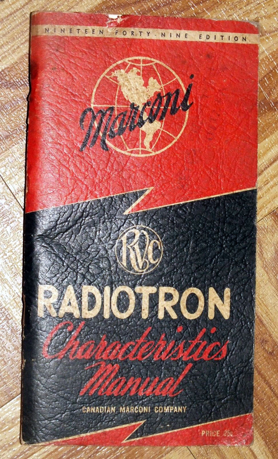 |
| Front cover of the RVC/CMC Tube Manual, 1949 edition. It is identical to the 1941 edition, |
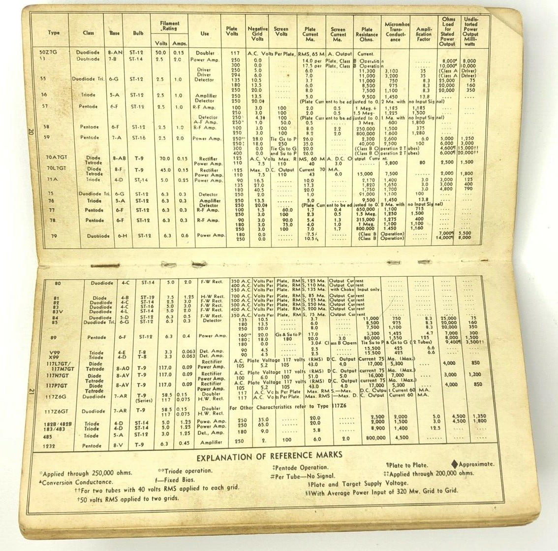 |
| Sample page from the manual. Click on image to enlarge. |
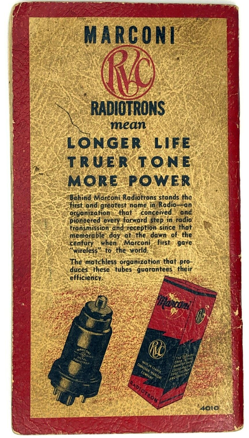 |
| Rear cover of RVC Tube Manual. |
| All images in this table via Ebay. |
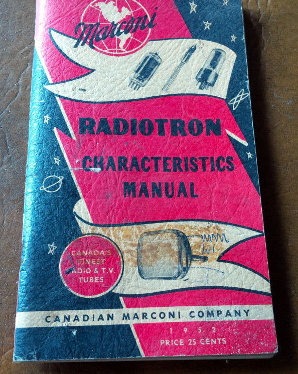 |
| Canadian Marconi tube manual from 1952. (Image via Kijiji) |
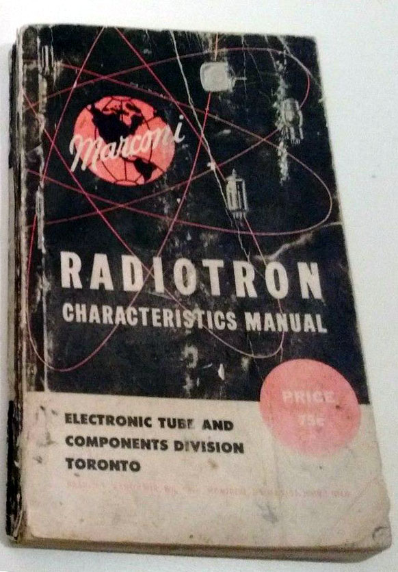 |
| A 223 page Canadian Marconi tube manual whose vintage is not known at this time. Included are the physical and electrical characteristics of all popular television picture tubes. It looks like the price was 75 cents |
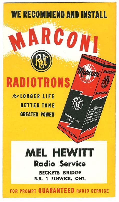 |
| Ink blotters, such as these, were used for advertising purposes when the vacuum tube was king along with pen and ink. (E-bay photo) |
 |
This is page 1 of a tube price list for July 1939, Click on image to enlarge, (Image via E-bay) |
How did RVC come to use the Radiotron trademark?RCA was formed in 1920 as an operating company for the purpose of providing ship-to-shore and transoceanic communication. It had no manufacturing facilities until the formation of a subsidiary company, namely RCA Radiotron . The earliest listing of "Radiotron" at the patent and trademark office (USPTO) is April 28. 1921 for application. It was issued in 1922, however its first use in commerce is 1920. The trademark was registered to the Radio Corporation of America. who in turn licensed its use to Canadian Marconi, Amalgamated Wireless of Australia, Westinghouse and other companies who were licensed by RCA to use its tube patents. There is no indication of any earlier registration of the trademark by anyone other than RCA.
DOUBLE AND SINGLE SIDED TUBE PRODUCTION.
In March, 1924, an important change went into production. Through the invention of Messrs. L.E. Mitchell and A.J. White, the exhaust tube was removed from the top of the bulb and brought out through the stem tubing. This change was of value not only because of the ease with which tubes could be handled on the exhaust equipment, it also eliminated one operation. It also paved the way for the later development of double ended tubes.
Investigation into difficulties occurring with the Armstrong superheterodyne (put on the market in 1924) led to the 1926 development of the first screen grid tube known as the UX-222. This was the first receiving valve which made use of the vacancy left by removal of the exhaust tube from the top of the bulb. The pin formerly used for the control grid (on a then standard 4-pin base) was assigned to the screen grid. Thus, we can see that original use of a grid cap was prompted by technical and mechanical design improvements.
Most of the above information was obtained from the 1937 RCA Manufacturing publication Vacuum Tube Design However, just as the introduction of a control grid connection at the top of the bulb was enabled by a design improvement, my guess would be that subsequent elimination of it was a further design improvement that simplified production and presumably reduced cost.
Examples of double /single ended metal envelope, octal tubes are as follows along with the year that they first saw service
6A7 - 1934
6SA7 - 19386k7 - 1935
6Sk7 -19386Q7 - 1935
6SQ7 - 1938Radio collector Gerry Ohara offers his thoughts on the advantages and disadvantages of both single and double-ended tubes.
The advantages double-ended tubes have includes greater separation between external grid and other connections in a small signal tube (potentially reducing unwanted feedback, etc.), and between the high voltage (top cap) plate connection and other connections in a high power tube, potentially reducing risk of arc-over and unwanted self-oscillation, plus it allows for nine connections in an octal tube. Disadvantages include more complicated construction process, eg. additional seal, and more awkward wiring (application dependent);
The advantages a single-ended tube has include simplified manufacturing methods, convenience of under-chassis connections/simplified wiring and potentially higher frequency operation due to shorted grid connections (application dependent). Disadvantages include reducing the number of connections available, and less separation between the grid connection and other connections.
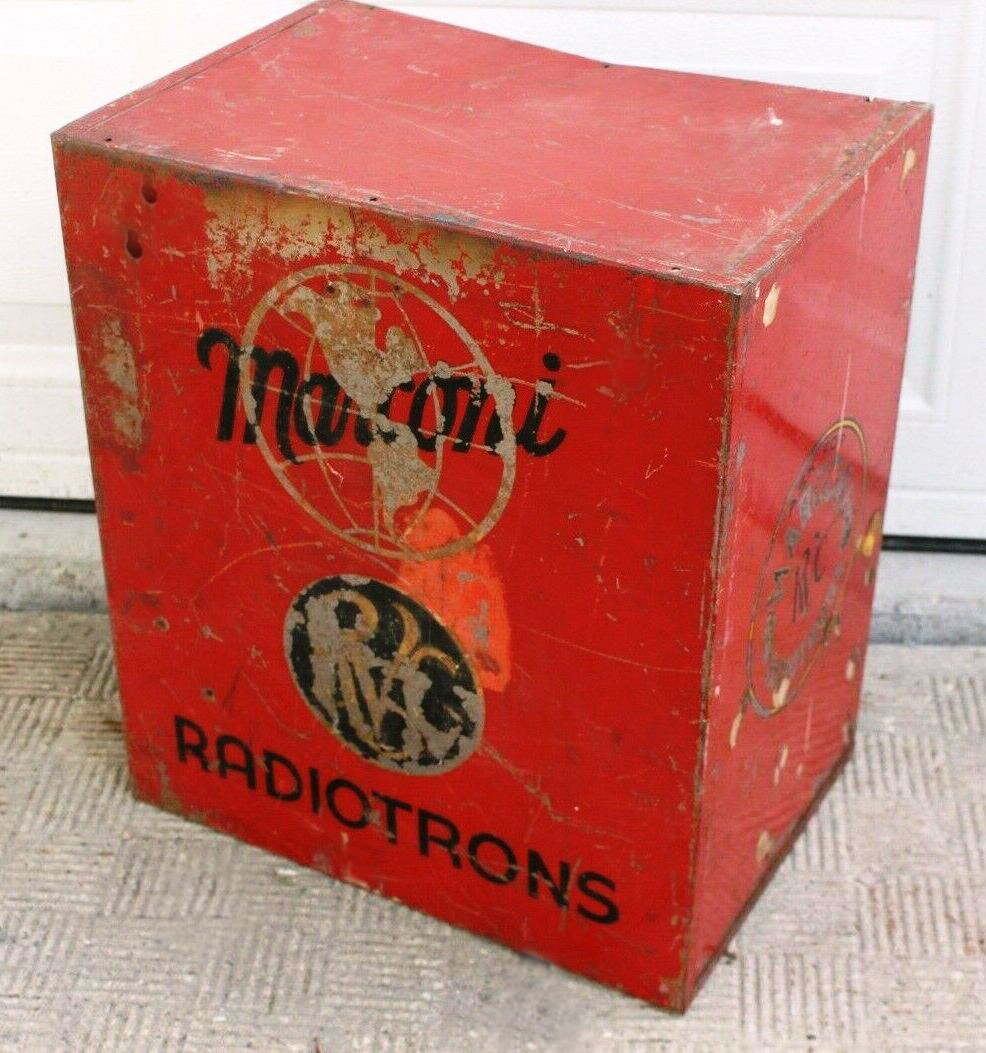 |
| Front view |
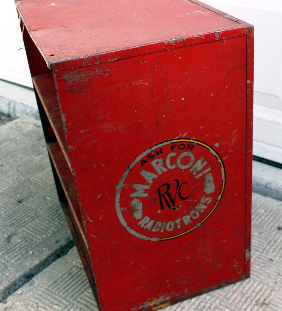 |
| Side view |
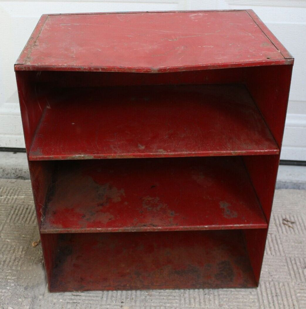 |
| Rear view |
| Measuring 18.5" x 16" x 11" , a Marconi dealer might have used this type of cabinet to store and advertise RVC tubes. (Photos via Kijiji) |
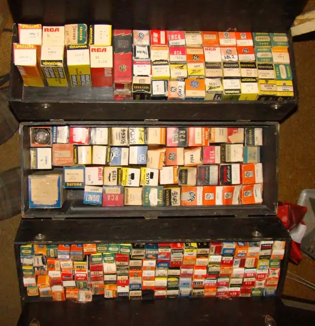 |
| In the 1950s and 1960s, in-home television servicing was a common method for repairing television problems. The serviceman would arrive at the customers residence with a tube caddy which was filled with the most popular tube types used in television receivers. THe tube substution method was the one widely used to repair TV problems. (Image via Kijiji.ca) |
Contributors and Credits:1) Pierre Lewis <leware(at)videotron.ca>
2) V24 and 'Q' photos by Ben <benam(at)rogers.com>
3) V24 Description http://www.r-type.org/exhib/aaj0135.htm
4) http://www.oneillselectronicmuseum.com/largephotos/decorphoto/marconiad1a.jpg
5) http://www.g3ngd.talktalk.net/marconi.html
6) http://www.r-type.org/articles/art-002.htm#03
7) Tom Brent <navyradiocom(at)gmail.com>
8) The Early Development of Radio in Canada 1901-1930 by Robert Murray.page 31
for RVC9) Jim Cross <jimcross(at)cfl.rr.com>
10) Lewis Bodkin <05bodkin555(at)gmail,com>
11) V24 and Q tube specs: Scientific Experimenter March 1921
12) The Early Days of Broadcasting 1920-1930 Page 309
13) Richard Knoppow WB6KBL <1oldlens1(at)ix.netcom.com>
July 30/24