Y.S.W.- 4A2 Shortwave Receiver


SPECIFICATIONS

Frequency Range: 240 to 12 metres (1250 KHz to 25 MHz)
Type 38758-YSW-4a2
Spec: Spec 38759
Circa: 1933
Comment: If anyone can provide additional information, please contact:  jerry.proc@sympatico.ca

ysw4a2_03_angle.jpg
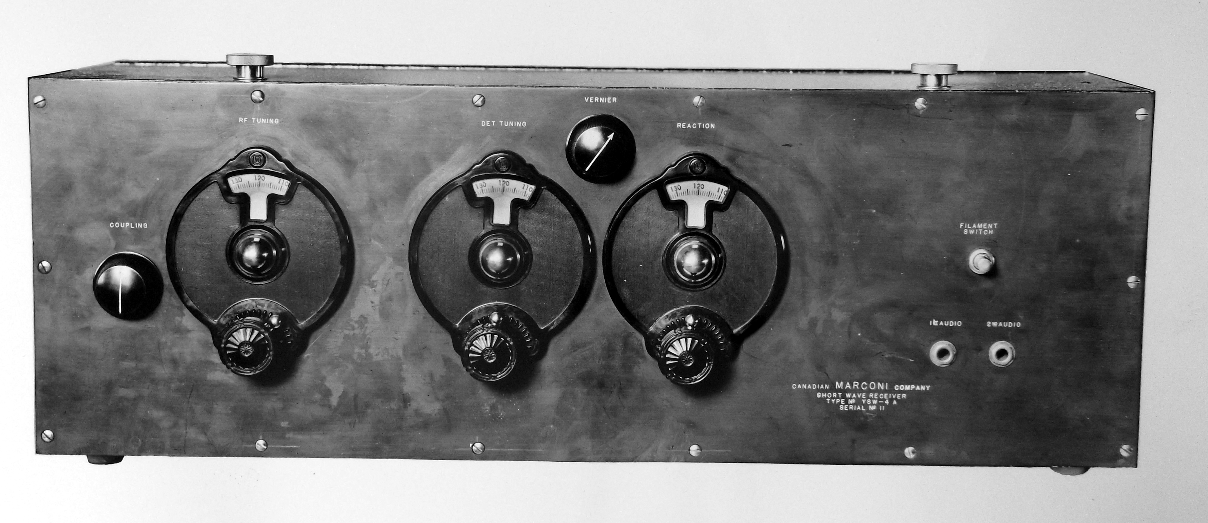
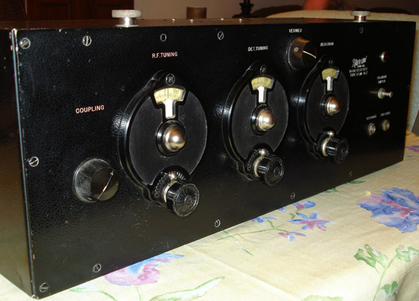
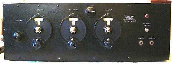
Above and below: Front panel views.
ysw4a2_01_front.jpg
ysw4a2_02.jpg
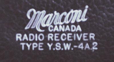
The model number is identified on the front panel. On top of the radio is additional identification which indicates Type 38758-YSW-4a2, Spec 38759 and wavelength range from 12 to 240 metres. 
ysw4a2_04_inside1.jpg
This particular receiver came with four sets of coils covering 12 through 85 meters. A notation on the schematic says that two optional coil sets were available to cover the rest of the tuning range. 
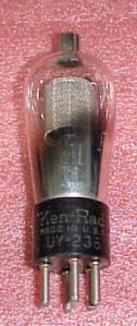
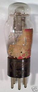
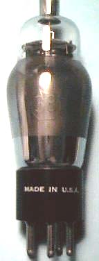
ysw4a2_05_inside2.jpg
The receiver was also accompanied with an internal factory memo dated April 22nd, 1933  and details alterations that were made "for operation with the automotive series of tubes". It uses 2 x 236, 1 x 237 and 1 x 238 type tubes. These are RCA's [1] version of the standard automotive types 36, 37, and 38. The number 2 was a designator for the RCA company. Other manufacturers of the period who made the 36, 37 and 38 tubes used their own designators.  As an example, Cunningham produced these tubes as 336, 337 and 338. Some 2xx series receiving tubes bear the prefix UY indicating the base type.

On the schematic, these tubes are designated as '236, '237 and '238 and the apostrophe likely represents the 'UY' basing prefix [2] or anything that the draughtsman wanted it to be. To study the characteristics of these tubes, please refer to types 36, 37 and 38.

ysw4a2_06_inside3.jpg
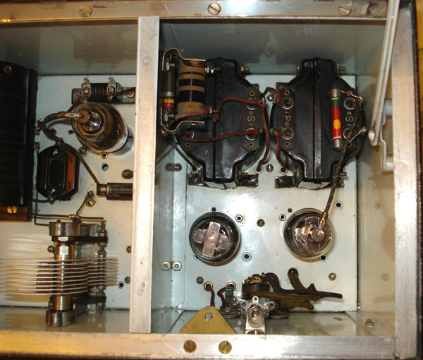
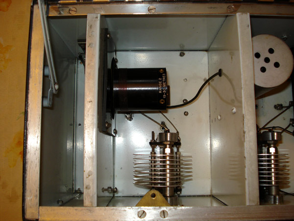
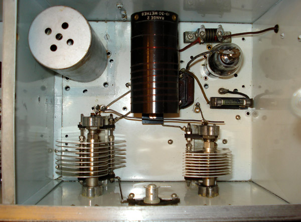
In the three interior photos above, the Range 2 (19 to 30 metre) coils are in place.
All photos in this table by Wayne Mackin 

Click to enlarge

ysw4a2_factory_letter_s.jpg This letter from Marconi details what changes are necessary in order for the YWS-4a2 receiver to use automotive type tubes. Of interest is the location from where the letter originated  because Canadian Marconi was headquartered in Montreal. It came from Yamachiche, just slightly west of Trois Rivières, Quebec. 
ysw4a2_schematic_s.jpg Schematic of receiver 
Letter and schematic provided by Wayne Mackin 

 
ysw_4a_dfsc4199.jpg
This is the YSW-4A variant. There is just a minor front panel difference between the 4A and the 4A2. Is the red indicator lamp original to the 4A2?  Download image to enlarge. (Photo provided by Lewis Bodkin.    


THE RECEIVER'S TUBES

ysw4a2_uy236.jpg ysw4a2_uy237.jpg ysw4a2_uy238.jpg
UY-236 tube image (Courtesy e-bay) UY-237 tube image. (Courtesy e-bay) UY-238 tube image. (Courtesy radiomann)
FOOTNOTES:

[1] RCA was a patent pool corporation, not a manufacturer, until they bought the Victor Talking Machine Co. in 1928.  So the early RCA superheterodyne receivers were actually built by GE and
Westinghouse.

[2]  The prefacing of type 236 with an apostrophe to denote dropping the two-letter basing prefix would be understandable in the early to mid 1930's.  Things like that came along with the revision of the drafting standards for tube internals to show the plate as a straight horizontal line at the top rather than a rectangle on one side, and the grids as horizontal dashed lines, a general
standardization of broadcast IF frequencies in the 450-470 KHz range, and the wholesale shift from 2.5 to 6.3 volt heaters.


Contributors and Credits:

1) Wayne Mackin <wmackin(at)rogers.com>
2) UY238 image   http://www.geocities.jp/radiomann/HomePageVT/GRPJVp/US38.JPG
3) http://www.vacuumtubesinc.com/TubeTidbits/AntiqueTubeEquivalents.aspx
4) Robert Downs <WA5CAB(at)cs.com>
5) HankVan Cleef <hankvc(at)lostwells.net>
6)  Lewis Bodkin  <05bodkin555(at)gmail.com>


Feb 16/18


Back to Equipment Listing