| Co-ordinate |
Quantity |
Model |
Description |
Comments |
|
|
|
|
|
| 2A |
1 |
MK-442/WLR-l |
Used for ELINT |
Need info |
| |
1 |
SG-333/WLR-l |
Used for ELINT |
Need info |
| |
1 |
S-99030 |
? |
Need info |
| |
1 |
? |
Audio SBL panel |
Need info |
| |
1 |
Fairchild 777 |
Oscilloscope |
Bandwidth? |
| |
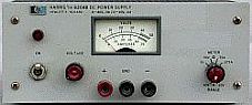
1 |
HP-6433 |
Power Supply |
0-32VDC 0-10 amps |
| Co-ordinate |
Quantity |
Model |
Description |
Comments |
|
|
|
|
|
| 2B |
1 |
R-390A/URR |
Receiver |
500 KHz to 32 MHz |
| |
1 |
R-1151/GLQ |
Receiver |
Need info |
| |
1 |
R-1307A/GR |
Receiver |
4 KHz to 812 KHz. Made by Rycom Instruments.
It was designed to provide accurate field strength
measurements of various transmitters. It is an all
mode receiver that be used to listen to about
anything one might find in the VLF range. |
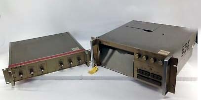
The NSA Damage Assessment report indicated what equipment was destroyed
and what was damaged. This is the actual
view of the equipment at coordinates 2, 2A and 2B. Legend Crosshatch
= destroyed; Grid = damaged.
This image shows the layout of the equipment
in each rack for co-ordinates 2, 2A and 2B.
If anyone can provide further details , please contact: jerry.proc@sympatico.ca
Contributors or Credits:
1) NSA Damage Assessment Report Pages 21 to 24 https://www.nsa.gov/news-features/declassified-documents/uss-pueblo/assets/files/damage-assessments/Cryptologic_Damage_Assessment_Vol_1.pdf
2) R390 image courtesy Wikipedia
3) R-1307A/GR image courtesy Radiomuseum.org.
4) R-1407 copy courtesy http://www.aa5tb.com/rycom.html
5) HP6204B power sypply specs https://testequipment.center/Products/Hewlett-Packard-6204B
6) HP 6433 power supply http://lcweb2.loc.gov/master/mbrs/recording_preservation/manuals/HP%20Mode%206433B%20DC%20Power%20Supply.pdf
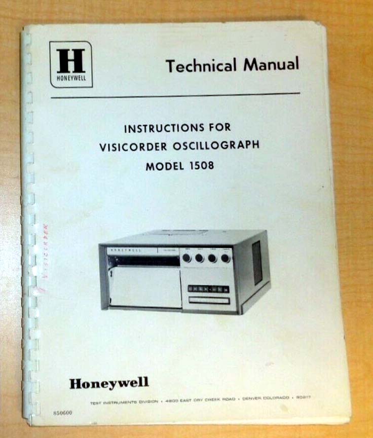
7) 1508 imfo via Chuck McGregor, K7MCG <cbmcgr@gmail.com>
Back to Home page
July 4/20