• ANNULET (AN/GYQ-102(V)1) was "a field scan” system.
A TTY terminal is provided for initialization of the system and for execution
of diagnostic routines. Two high-speed printers present signal-related
information to operators and supervisors.” [Both sets of quotations from
"[U.S.] Army Modernization Information Memorandum", 1985]. It's not clear
exactly what a lot of the foregoing means, but KEELAN has been described
as a printer collection system (presumably mostly for Soviet radioprinter
traffic) and ANNULET as a processing system; the two seem often to have
been deployed together. It was introduced at US Army, Air Force, and Navy
sites beginning in the early to mid-1980s. KEELAN was reportedly deployed
at Leitrim in 1985 and Alert in 1986.
• MEDIATOR – This is a Morse and /non-Morse integrated collection
system,.
• CENTREVELIC
A review of the 291 trade conducted in 1997 listed CENTREVELIC Operations
as one of the roles played by trade members but didn't explain the
meaning of the term. Associated appendices showed all the positions occupied
by 291ers at the time. These included 19 positions listed as CV OPs --
presumably CENTREVELIC operators -- and an additional 3 probably related
"C/V" positions, all shown to be at Leitrim. The information in the appendices
is a little hard to interpret because it reflects the situation during
but before the completion of the remoting project. Significant numbers
of 291ers are still shown at Gander and Masset, for example. No listing
is shown for Alert, but 34 of the positions at Leitrim are listed as "Alert
offsets", which may mean that those positions were still at Alert at the
time. If this is the case, possibly they were listed under Leitrim because
they were officially on the station's strength and only attached-posted
to Alert. For what it's worth, none of the CV positions are designated
as Alert offsets. That said, a fellow named Henri St. Louis helpfully posted
a resume in 1996 that said he served as a "Radio Technician, CENTERVELLIC
[sic] /PUSHER TECHNICIAN" at Alert and Leitrim in 1995-96. He described
his role as "Part of the Operations team that installs, maintains and modifies
HF Short Duration Collection & Direction Finding Resolution DF System,
Experimental Ionospheric Testing System. Specific experience with Unix
based computers and TCP/IP networks." This suggests that CENTREVELIC was
related to the Pusher system and that it pertained to the Pusher at Alert
as well as the one at Leitrim. Still, there seems to be some difference
between the two, as the 291 trade review listed "Netted HFDF Operations"
as its own role, distinct from "CENTREVELIC Operations". At various times
in the past I've thought that CENTREVELIC and the Pusher were one and the
same, but as you can see from the foregoing I'm currently doubtful about
that
• LONGROOT - CHATgpt had tnis to say about LONGROOT: "In
the context of radio direction finding (DF), LONGROOT refers to a specific
system, technology, or enhancement used in Canadian or allied military
and intelligence applications. Based on known references from declassified
or open-source material and terminology patterns, here’s what is known
or inferred about LONGROOT in DF:
LONGROOT Overview (Radio Direction Finding Context)
Definition:
LONGROOT appears to be a Canadian (or Five Eyes) code name for a DF-related
processing system, likely developed or deployed by military signals intelligence
units. It's not a commercial or generic DF term but rather an internal
system designation.
LONGROOT is associated with:
• Enhanced Automatic Direction Finding (ADF).
• Integration with radio intercept and analysis systems.
• Possibly includes EADF (Enhanced Automatic DF) capabilities—an advanced
DF mode that automates signal location from intercepted transmissions.
• High-speed signal processing for emitter geolocation.
Usage:
Deployed at Canadian Forces Station s(CFS) and other SIGINT facilities.
Possibly used aboard mobile or deployable platforms (vehicles, aircraft,
or field systems).
Connected with real-time signal intercept, classification, and triangulation
of emitters".
In addition, this name appears in the glossary of a 1997 USAF publication,
Sentinel Force 2000+, that can be found on the website of the Federation
of American Scientists It gives this definition: Enhanced Automatic DF
(EADF) - an upgrade to current DF processors at approximately 24
sites worldwide."
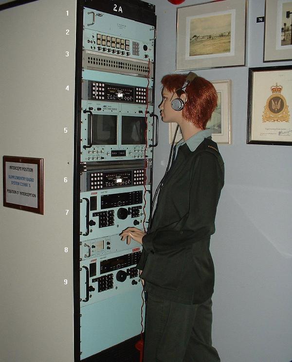
DUAL INTERCEPT POSITION 1980's and 1990's
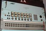
PYLON 095 RF (Double) Distributor Panel
Pylon Electronics provides the following description for the 095 RF
panel since there is no manual for it. "We do know that the circular military
connectors at the back of the unit were connected to each of the BNC connectors.
One circular mil connector was attached to half the BNC connectors and
the other mil connector was attached to the other half of the BNC connectors.
Unfortunately, we do not know how this panel was connected or used in the
field."
PYLON 364A Audio Panel
The Pylon 364 Audio Panel is a dual channel, pushbutton operated audio
line selector in which any combination of six audio inputs can be selected
and mixed. This unit can also be interconnected to a telephone line which
supports tone dialing with a provision to patch the audio line selector
output to the telephone line. Revision 3 of the manual for the 364A
is dated February 1991 so it's assumed the 364 was introduced to the marketplace
prior to that time frame.
SPECIFICATIONS
Audio Line Input:
Number of lines - 6 maximum
Impedance - 600 ohms, balanced.
Level - 0 dbm
Gain - individual front panel control for each line.
Audio Output:
Front Panel - Two stereo headset jacks (ring, tip,
and sleeve).
Rear Panel - Two pair screw terminals ( in parallel
with headset jacks)
Impedance - 600 ohms. Level - 9 dBm each channel
+ 20 dBm max.
Frequency Range - 250 Hz to 4 KHz +/- 3 dB
Intercom:
Front Panel - One microphone jack (tip and sleeve)
input - Uses left channel of headset jack output (when
activated by the ICOM switch)
Volume control for solid state Ringer.
Uses Northern Telecom Digitone Push Button Dial.
Selector (hook) Switch is illuminated when selected.
Rear Panel:
One pair screw terminals for Northern Telecom handset
- One pair screw terminals for Mitel
SX-2BB two-wire PABX connection.
Phone Patch:
Front Panel - Patch Switch - (illuminated when "patched")
Gain control
Coupling - Transformer
Level -l0 dbm
Power Supply: Input 115 VAC, 60 Hz, 20 VA
OPERATING PROCEDURE
To provide a better understanding of the how the audio panel works,
here are some excerpts from the operating manual.
A) Line Selection
The six input signals may be selected on the left, right, or both channels
by depressing the appropriate line/channel button. When the line is selected,
a lamp in the selector switch will be illuminated.
A level control for each line is provided below the switches.
All six lines may be selected individually or in combination to appear
on the left, right or both channels.
The output is available at both the headphone output and monitor output
on the front panel as well as the output terminals on the rear panel.
B) Intercom
When connected to a telephone line the left headphone, in conjunction
with a microphone, may be used to access the phone line. Alternatively,
a handset may be used. An incoming call will be signalled by the I/C lamp
flashing and by the tone ringer, if it is turned on. The control under
the tone ringer speaker contains an ON/OFF switch as well as a level control
for the tone ringer. To answer a call, depress the I/C switch and use either
the handset or microphone/headset combination, whichever is connected.
To disconnect from the line, depress the I/C switch.
The indicator lamp should then go out. To place a call, depress the
I/C switch. Once a dial tone is obtained, place your call using the front
panel keypad to dial.
C) Patch
When the phone line is in use, you may patch the audio selected to the
right headphone channel into the phone circuit. To do this, depress the
Patch switch. The level control below this switch allows a small adjustment
of the level fed to the line.
SIGNAL PATCH PANEL
The Signal Patch Panel t was capable of distributing signals up to 1
MHz in frequency as dictated by the upper frequency response of the Pylon
3789 distribution amplifier that was connected to it. The connectors are
industry standard and designed to handle low power video and RF signals
of 75 ohm impedance and up to 1 GHz. In spite of having nearly identical
appearances, the 50 and 75 ohm version of the plugs and jacks are not compatible
and they won't mate. The markings on the front panel are: PY3789 #1 OUTPUTS
A1, A2 A3, A4, B1, B2, B3, B4, C1, C2, C3, C4. This is repeated on the
right side for OUTPUT #2 so this means the panel can accommodate the outputs
from two 3789 amplifiers. In addition, the panel interfaces the BNC
style output jacks on the 3789 rear panel to the Trompeter jacks.
What is described is the arrangement for the top row of jacks. The bottom
row of jacks is unlabelled. Also, the three rightmost jacks in the bottom
row have covers over them thus rendering the panel asymmetrical.
Chip Veres, a communications technician with WLRN TV and FM in Miami,
FL suspects that the 3789 panel might have been used for VLF-LF signals
where the phase is important (PSK). " Its bandwidth is not enough for video,
let alone HF, but the phase is specified to error less than 10 degrees
at 1 MHz. The station operator mentioned the availability of several
Beverage antennas, so maybe this amp was used to get the long-wave signals
to different receivers. It may also have carried a phase reference
signal from the cesium clock".
Chris Collin offers some additional details about the panel. "At one
time, we used a combination of jacks. I remember using 1/4" phono
jacks for audio, BNC along with Trompeter jacks all on the same rack.
The patch panel could become a nightmare, especially in a SIgDev position!
We also had adapter connectors which could convert from one connector
type to another.
Some situations had antennae being attached to patch panels. For anything
above LF, the connectors needed to be of the higher performance variety.
We would also need to patch video in some situations, or IF frequencies,
often 22.4MHz . In the end, I suspect it was just easier to install Trompeter
jacks everywhere, as this reduced the requirements for all kinds
of cables and connectors, at least at the operator level. SigDev'ers usually
had access to various connectors, as we would sometimes bypass the
jack panel, and go directly to the equipment especially for a new or experimental
situation, and where the jack at the back of the equipment was not
connected to the patch panel.
SigDev'ers would frustrate technicians at times by hooking up gear in
new and novel way as an experiment in order to process a difficult signal.
Technicians liked things all sorted and installed neatly and correctly
but we would often run lines in and out of the racks in new and strictly
unofficial ways!
For most situations, BNC connectors would have been fine, but
there were advantages to having a patch panel like the Trompeter type for
ease of use, training, and expansion capabilities. Generally speaking,
for most positions the patches would be made once and rarely did they change".
Mike Bostwick confirms that panels weren't utilized very much on a normal
intercept bay.
PYLON 3789 DISTRIBUTION AMP (Out of View)
The Pylon 3789 Distribution Amplifier (circa 1980) is a 19" rack mountable
unit, designed to perform the
following functions:
a) Distribute each of 3 channels to 4 outputs each with a maximum isolation
between the lines.
b) Provide by means of a calibrated R.M.S. voltmeter, a method of monitoring
all input and output signal levels.
c) Display by 3 front panel LED's, an input overdrive condition.
SPECIFICATIONS:
Inputs : Up to 3 rear panel BNC connectors; 50 to 600 ohm termination;
up to 5 volts RMS maximum.
Outputs: Up to 12, rear panel BNC;. Maximum drive to a 50 ohm load
is 5 volts RMS. Capable of withstanding
a momentary short circuit
Frequency Response: flat to 1 MHz. A phase shift of 30° is observed
between input and output at 1 MHz.
Size: 3.5in. H x19in. W x 12.5in. D
Weight: 11 lbs.
Power 115 VAC, 60 Hz, 36 watts nominal; 60 watts maximum.
A 3789 manual can be found
here.
 |
|
3789 Front View (Photo courtesy Pylon Electronics)
|
|
 |
|
3789 Rear View - the 3 inputs are at the right side. Photo
courtesy Pylon Electronics)
|
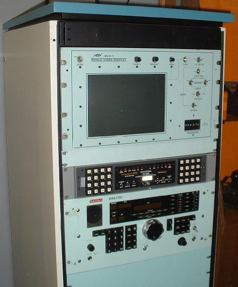
M7000 COMMUNICATIONS TERMINAL
The M-7000 was introduced by Universal Radio in Columbus Ohio in the
1987-1988 time frame by it's President, Fred Osterman. It was built by
Digital Electronic Systems Inc. of Florida. The May 1989 edition of the
RTTY Listener monthly periodical announced that the Canadian government
purchased fifty Universal M7000's with video, fax and real time clock options.
Reception Modes:
Morse Code 5 to 120 WPM with Auto ranging
RTTY Baudot 45, 50, 57, 75 and 100 baud (60, 66, 75, 100 and 132 WPM)
RTTY Baudot 37-251 baud non-standard rates
SITOR A ARQTOR, Amtor A
SITOR B FECTOR, Amtor B, NAVTEX
ASCII 150, 300, 600 and 1200 baud.
ARQ-M2 TDM 86, 96 and 100 baud.
ARQ-M4 TDM 172, 192 and 200 baud.
Packet 300 and 1200 baud.
FAX Facsimile 60, 90, 120 and 240 LPM AM/FM
VFT [FDM] HF 8/12/16/24 Channel.
VFT [FDM] SAT 50 Channel. [in v7 only]
ARQ-E 48, 64, 72, 86, 96, 144 and 192 baud. [in v5/v7 only]
ARQ-E3 48, 64, 72, 86, 96, 100, 192 and 200 baud. [in v5/v7 only]
ARQ-S 4, 5, 6 or 7 character groups. [in v7 only]
SWED-ARQ 3, 9 or 22 character groups. [in v7 only]
FEC-A 96, 144 and 192 baud. [in v7 only]
FEC-S 96, 100, 144, 192 and 200 baud. [in v7 only]
Some Key Features:
Speed Readout: Indicates the incoming RTTY transmission rate.
Diversity Reception
Filter Control Wide-Narrow-Normal
Four Alphabets: ITA2, MIL, TELEX, Cyrillic
Variants:
The Universal M-7000V2 was an M-7000V1 production unit that had a Ver2
ROM upgrade adding ARQ-E and ARQ-E3 modes. The Universal M-7000V3
was an M-7000V1 production unit that had a Ver 3 ROM upgrade adding:
ARQ-E, ARQ-E3, ARQ-S, FEC-S, FEC-A and SWED-ARQ modes. The Universal M-7000V5
production version added these modes over the Ver 1: ARQ-E
and ARQ-E3. The Universal M-7000V6 was an M-7000V5 production unit that
had a Ver6 ROM upgrade adding: ARQ-S, FEC-S, FEC-A and SWED-ARQ
modes. The Universal M-7000V7 production version added these modes over
the V1: ARQ-E, ARQ-E3, ARQ-S, FEC-A, FEC-S, SWED-ARQ and VFT
50 channel.
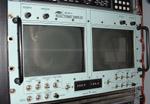
PYLON DVD-1 Display
The DVD-1 is a programmable dual channel display instrument enabling
an operator to visually check the integrity of incoming BAUDOT and ASCII
formatted data. Incoming BAUDOT data is converted to ASCII and then retransmitted
at 2400 baud. If the conversion of BAUDOT encoded data to ASCII is not
desired, an internal jumper may be installed for either channel. When installed,
the affected channel(s) will retransmit BAUDOT encoded data at the incoming
baud rate (up to 19,200 baud). Incoming ASCII data is retransmitted at
the incoming baud rate (up to 19,200 baud).
If the operator must read the incoming data to check its integrity,
the incoming baud rate needs to be limited to approximately 600 baud. This
rate can be increased to 2,400 baud if the operator is visually scanning
specific data fields or characters. Higher baud rates will scroll the display
too rapidly.
The Serial Video Module is a programmable video interface providing
data conversion and communications. This module converts incoming BAUDOT
encoded data to ASCII (unless the data conversion mode is disabled) before
it is transmitted. Incoming ASCII data is retransmitted in the same format.
All incoming BAUDOT and ASCII data is stored in a screen memory for display
via the CRT.
Serial format and baud rate of the Serial Video Module's input and output
can be selected independently.
BAUDOT or ASCII encoded data is received by one port of a dual asynchronous
receiver/transmitter.
A microprocessor polls the receiver for activity. Incoming BAUDOT data
is converted to ASCII
and then transmitted at 2,400 baud. If the data conversion mode is
disabled, the incoming BAUDOT data is retransmitted in the same format
and incoming baud rate. Incoming ASCII data is retransmitted in the same
format and baud rate (up to 19,200 baud).
KEY FEATURES:
* BAUDOT/ASCII data communications and video display.
* Full 70 character x 25 line display.
* 7 x 7 or 8 x 8 characters displayed in 8 x 8 character cell using
9 x 9 pixel array.
* Unrecognized character indicator.
* Variable baud rate 0 to 19,200.
SPECIFICATIONS:
* Dimensions: Height 267 mm (10.5 in.) Width 483 mm (19.0 in.) Depth
533 mm (21.0 in.)
* Weight: 24.2 kg (53.2 lb) net
* Power requirements: 120 VAC, 60 Hz, 0.8 A
Revision 1 of the manual is dated 1 March 1988 so its likely the DVD-1
was introduced prior to that time frame.
PYLON 125 Tuning Indicator
The PYLON 125 Tuning Indicator is a highly accurate display which was
used as an aid in tuning a receiver to a particular frequency. A 2" x 2"
square CRT display provides the visual display. This device can be used
with receivers which employ either 100 kHz, 455 kHz or 1.4 MHz Intermediate
Frequencies (IF). The desired IF frequency of operation can be selected
by changing a crystal on the Tuning Indicator Module at the rear of the
unit and reselecting the associated DIP switches. Setting up the
desired IF frequency is done when the equipment is first installed and
would remain that way for the duration of the in-service interval.
For 1.4 MHz , 455 kHz and 100 kHz operation, crystal frequencies of 2.82
MHz , 1.86 MHz and 3.52 MHz are required. Horizontal divisions on
the CRT graticule correspond to 100 or 200 kHz steps depending if the Magnifer
is in the 1X or 2X position. The 125 Indicator was first introduced
by Pylon in 1981.
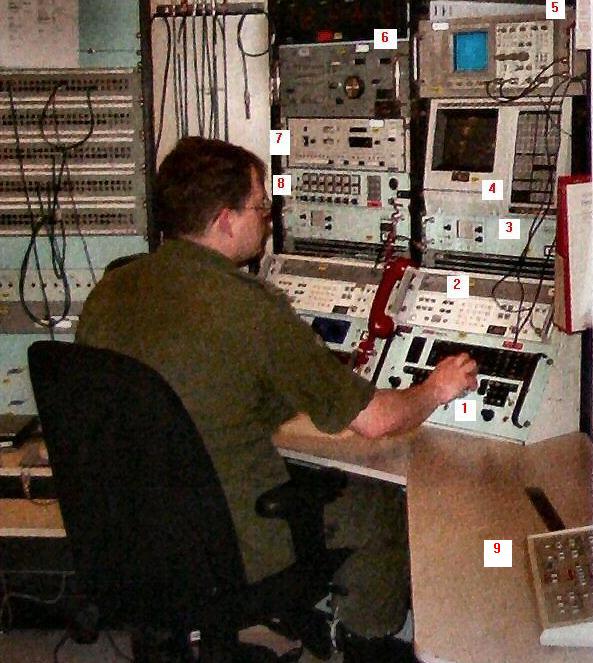
Chris Collin provides more details about the various equipment
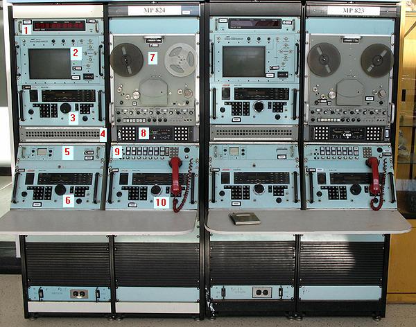
configurations in a Multipurpose Position. "MP simply meant "Multi-Purpose,"
as opposed to the "MM" or "Manual Morse" positions, or the "SD" for SigDev.
As such, there was no real standard layout, and in fact, different MP positions
in the same room could look different, depending on the tasking.
Example - some might include equipment for signals other than Morse and
teletype (RTTY). The Universal M7000 terminal, and then the M8000
were good in that way, since they could copy several common signals, and
having a digital output, the data could be sent to a computer for
processing for signals that those devices could not process. They
could also be computer controlled, which made them great for sites under
remote control. Previously, separate equipment was required to copy
RTTY signals and other signal types. Certain positions might be for
printer only ("PP" positions), while others were for other types of signals.
However, most MP positions could handle a variety of signals.
After the end of the Cold War, as tasking changed, so did the racks.
Different equipment came into use, as different signals were being copied.
While much equipment was designed to be flexible (eg., the M7000), typically
certain jobs were done on certain positions, and the equipment for those
racks pertained to the particular tasking for that position. Example- the
rack layout for signal Y from country X might be different from the racks
used to copy signal X from country Y. Thus, the examples one sees
in the Leitrim building lobby are real, but they do not show the entire
picture, only a sample representation.
Generally, the racks would be ganged together - normally at least 2,
but 4 sometimes 6 were also observed. The "Printer Position" might
have even more, e.g., 8 racks. Each position would be MP, with the
designator also indicating the station e.g., MP801 being Leitrim, while
MP501 would be in Gander. If memory serves, Alert would be MP001,
and Masset MP101. The 4 (or whatever) racks together would all be
part of MP###. If I remember right, the Alert SigDev position (SD001)
had 13 racks for one of my tours.
The tape recorders could be used for various tasks. Often, voice
signals were recorded so that the linguists could replay the transmissions
over and over again, in order to copy the "gists" more accurately.
New or unusual transmissions were supposed to be recorded, in order for
the Signals Development section to be able to do their analysis later on.
Also, during busy times, a signal might be recorded for later processing.
The recorders had 4 tracks:
a) Track 1 had a digital time signal from the atomic clock
b) Track 2 had a 100 Hz tone (also produced from the atomic clock)
which was used as a servo to sync the playback to a very high degree of
accuracy.
c) Tracks 3 and 4 were for the signals themselves, usually a receiver
AF (Audio Frequency). As the M7000 (and similar) demodulators used
AF, this was fine for processing from the playback.
For VLF positions, the antenna output could be recorded directly, and
thus signals reproduced and studied or copied at a later time.
I remember the SigDev positions getting new high-quality reel to reel
tapes sometime in the mid-1980's. They were a much darker brown,
and had higher fidelity than the usual tapes. They were also much
more expensive - $25 per tape, as opposed to the few dollars for the regular
tapes. Thus, each had a SigDev sticker on the reel, to ensure it was used
only in SigDev."
This reference was found on the web for the tape recorder: AN/TNH-21
Recorder-Reproducer Set, Sound, Instruction Manual, National Security Agency,
Fort G.Meade, MA, December 1973.
