The AT-3 transmitter was designed and built by RCA Canada, (Montreal) for the Royal Canadian Air Force. This was on the direction of Air Vice Marshall (AVM) Ralph McBurney who was the RCAF's Director of Signals when WWII started. The Canadian Army used the same transmitter but designated it as the C-33 set. CAP (Canadian Air Publication) No. 63 identifies it as RCAF stores number 10D/1272. RCA also lists the AT-3 as the TE-176 and also as Wireless Set 33 in the manual dated June 1942. Under model TE-176, the transmitter is part number is #MI-22106 while the remote control is #MI-22038-B. The AT-3 was painted blue while the C33 was painted brown.
The earliest known reference to the WS33 set comes from the "History of the Royal Canadian Corps of Signals, 1903 to 1961". This is an official history compiled by the Corps and printed in 1962. The WS33 was known as the C33 or "Maple Leaf". It is basically an RCAF AT-3 in a different colour and was primarily an Line of Communication(s) Signals transmitter.
The first reference of Army use is dated January, 1943. To quote the book:
"Practical experience was gained by No. 4 Technical Maintenance Section which modified and installed almost all of the C33 sets about to be taken into use by the Canadian Army. These sets had been originally designed as RCAF ground stations. At the instigation of Major P.D. Smith of First Canadian Army Signals they were now equipped with pressel switch control, their receivers detached to be kept in other vehicles, their current consumption reduced with the use of new remote controls, and the sets mounted in new vehicles."One interesting use of the C33 is from Operation Totalize, the attack on Falaise. The attack took place at night so to keep everyone on course, the C33 was used as a navigation transmitter!
"To keep them on course (tanks) two main methods were adopted, both highly unusual. Tracer shells fired over the tanks by anti-aircraft Bofors guns showed the direction of advance and a novel directional beam was devised and operated by Signals to guide the tank drivers in a way an airplane pilot is brought in "on the beam". The equipment for this job was of highly makeshift order (using, among other things, electric windshield wiper motors borrowed from convenient jeeps) but it worked - a tribute to Signal's renowned ingenuity.David Lawrence relates some AT-3 history. "The contracting procedure was very efficient. At the start of the war, AVM McBurney invited representatives into his office from RCA Canada, Canadian Marconi and Northern Electric Canada. He told them that the RCAF needed three wireless sets - a general purpose one for aircraft use, a small one for fighters and a big ground station transmitter. After one hour's discussion he said, "RCA, you can build the ground station (this became the AT-3); Marconi - you can build the fighter set and Northern, you can build the general purpose set (which became the AT1/AR2). Any questions? No! Get out of my office and get to work." This story was told to me by AVM McBurney while we stood in front of an AT1/AR2 and an AT-3 during the opening of the Military Communications and Electronics Museum in Kingston, Ontario.Using No. 9 and No. 33 sets to transmit a directional beam, signals in the form of dots from one set and dashes from another were to be heard in the earphones of the tank crews. The driver kept his tank on course by maneuvering so the dots and dashes were heard in his phones at equal volume.
Transmission stations had to be set up in the line, with operators supplied by 2nd Canadian Corps Signals who supervised the siting and operation of the sets."
SPECIFICATIONS
* Frequency range: 2.5 to 20 MHz.
* Frequency Control: Master Oscillator or 1 of 2 crystal controlled
channels.
* Power : 300 watts out.
* Modes: CW, MCW or VOICE
* Keying: Telegraphic keying to 60 words per minute, either CW or MCW.
The radio frequency generating
oscillators are keyed for CW operation. On MCW only, the
modulation, and not the carrier, is keyed.
* MCW: The carrier is modulated by a 1,000 cycle per second tone
* Voice Performance: Over the frequency range of 400 to 3000 cycles,
the overall distortion does not exceed
7.5% for 85% modulation.
* Tthe AT3 is designed for a capacitive load at the operating
frequency and an impedance from 40 to 100 ohms.
* Remote Control: Permits operation of transmitter up to 10 miles distance.
* Power Input: 110 VAC , 60 Hz,
1.75 kw maximum draw. Operation at 220 VAC 25 Hz requires
a frequency changer #10D/1274.
* Dimensions: AT3 Transmitter is approximately 68 inches high, 32 inches
wide and 22 inches deep.
Remote Control is approximately 9-3/8 inches high, 12-5/8 inches wide and
11-3/4 inches deep.
* Weight: 630 pounds for the AT3; Remote Control is 35 pounds;
Frequency Changer is 625 pounds.
* Operating power: 25 or 60 Hz for AT-3; the C-33 only ran on 60Hz
* Manual ID: IB-176 for AT-3 and C-33
BLOCK DIAGRAM
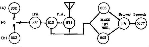 |
| The operating frequency and mode was selected by using the telephone style dial on the transmitter. The 802 (transmitting pentode) and 805 (high µ transmitting triode) tube types, introduced in 1935 and 1936 respectively, could operate up to 30 MHz. (Diagram courtesy RCA) |
CONTROLS and INDICATORS
(a) The following controls, necessary for routine tuning and operation of the transmitter, are located on the .front panel.
Master Oscillator-Crystal Oscillator switch for A channel
OSCillator TUNING control for A channel
I.P.A. TUNING control for A channel
I.P.A. BANDS switch for A channel
P.A. TUNING control for A channel
P.A. BANDS switch for A channel
ANTenna COUPLING control for A channel
ANTenna LOADING control for A channel
Master Oscillator-Crystal Oscillator switch for B channel
OSCillator TUNING control for B channel
I.P.A. TUNING control for B channel
I.P.A. BANDS switch for B channel
P.A. TUNING control for B channel
P.A. BANDS switch for B channel
ANTenna COUPLING control for B channel
ANTenna LOADING control for B channel
Master OFF-ON switch
OPERATE-TUNE switch
TELEPHONE-TELEGRAPH switch
LOCAL-REMOTE switch
Dialing OFF-ON switch
PLATE-ON-STANDBY switch
Impulsing Dial
Switch for test meter
Located just below each tuning control is a friction lock to prevent
accidental movement of a control once it has been set. All switches are
provided with positive positioning detents.
(b) The following meters are located on the front panel to facilitate tuning and to provide a check on performance.
ANTenna CURRENT for A channel
ANTenna CURRENT for B channel
P.A. PLATE CURRENT
I.P.A. PLATE CURRENT
MODulator CURRENT (cathode)
P.A. PLATE VOLTS
MODulator FILament VOLTS
LINE VOLTS
A test meter that may be switched to read
REMOTE LINE current
AUDio OSCillator plate current
V.O.C. Key Relay current
FIRST AUDIO plate current
DRIVER CATHODE current
MODulator GRID current
I.P.A. GRID current
P.A. GRID current
OSCILLATOR plate current
(c) The following controls when once set do not ordinarily require further adjustment and are located inside the transmitter:
MICrophone VOLTS (R707)
AUDIO GAIN (R505) ,
Audio OSCillator OUTPUT (R50l)
P.A. PLATE VOLTS adjustment potentiometer (R6l0)
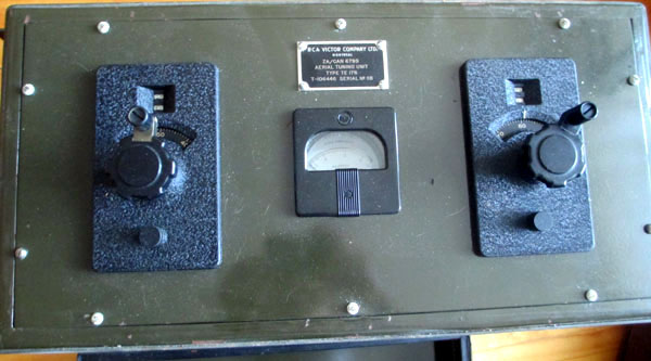
(d) The following controls and meter are located on the panel of the Type AT3 Remote Control:
OFF-ON switch
TELEPHONE-TELEGRAPH switch
Impulsing dial
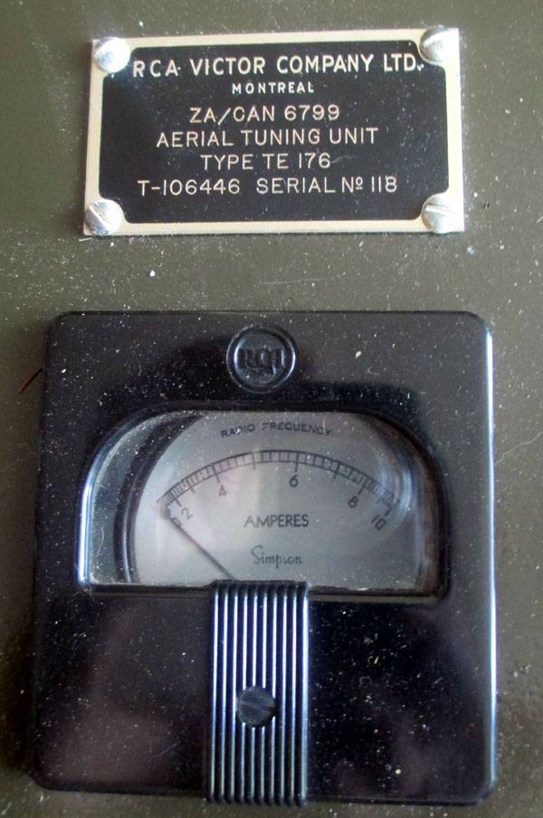
LINE current meter
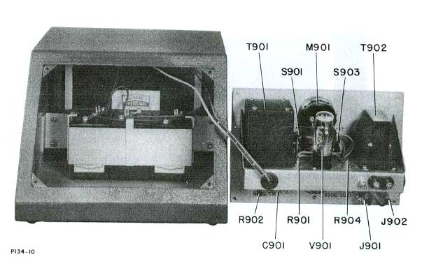
(e) The OSCillator OUTPUT control R90l and MIC. OUTPUT control R904 are located inside the Remote Control unit.
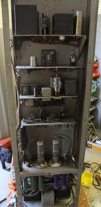
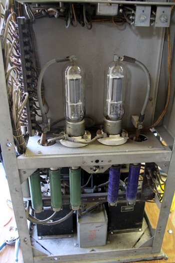
TUBE COMPLEMENT
The vacuum tubes used for the different circuits in the AT3 transmitter are:
R.F. Oscillators 2 x 802
Intermediate Power Amplifier 1 x 807
Power Amplifier 2 x 813
Audio Amplifier 1 x 6SD7
Modulator Driver 1 x 807
Modulator 2 x 805
Bias Voltage Rectifier 1 x 5Z3
Intermediate Voltage Rectifier 2 x 866
High Voltage Rectifier 2 x 872
Audio Oscillator 1 x 76
V.O.C. Control 1 x 6F8G
(b) The type AT3 Remote Control uses:
Audio Oscillator 1 x lH4G
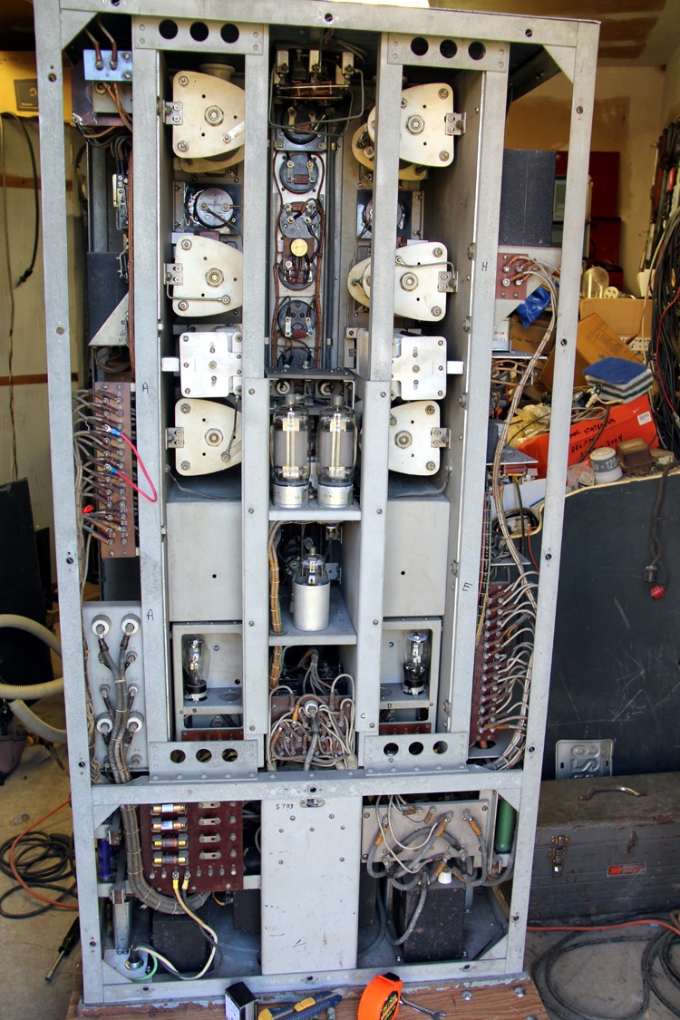
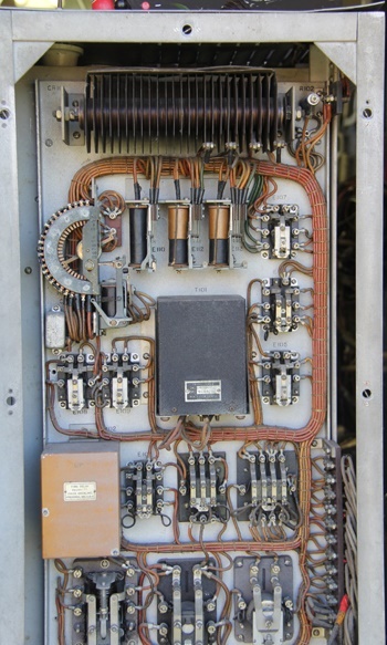
TRANSMITTER
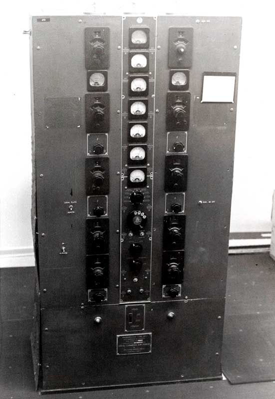 |
| VAK (Victoria Coast Guard Radio) had two AT-3 transmitters at one time. The AT-3 depicted in the above photo was installed at Sheringham Point, the station's transmitter site. This is how the transmitter looked in April 1969. The other AT-3 was located at the VAK Operations Building and served as a backup 2182 kHz (distress) transmitter. Both AT-3 transmitters were replaced with SSB transmitters several years later. (Photo by Frank Statham) |
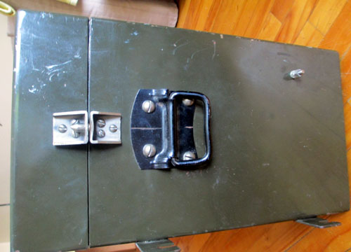
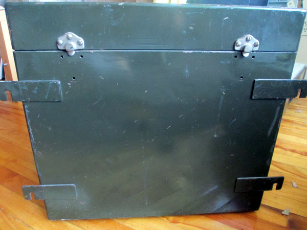
REMOTE CONTROL
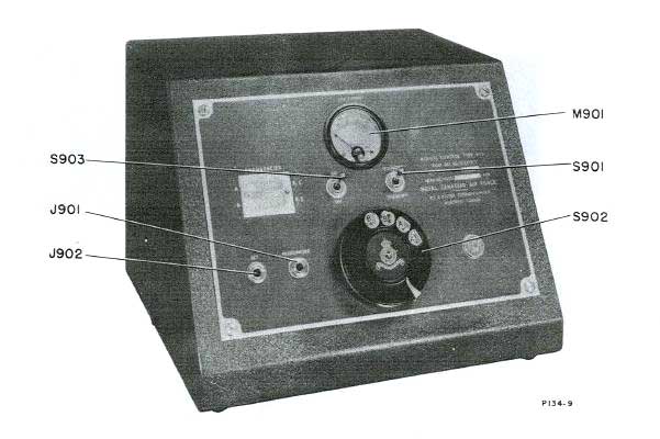 |
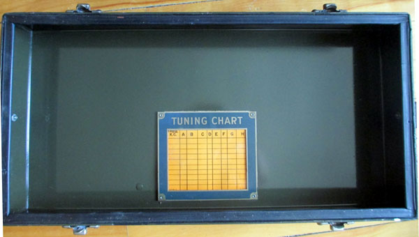
| #10D/1273 Remote Control - front view (Image by RCA Victor)
The AT3 was designed for service remote from air fields and controlled by a telephone type dialing system which allowed remote control over a standard phone line. This system allowed changing channels and emission types remotely with no operator present at the transmitter. This system is delicate and a bit of a pain to work on and trouble shoot. |
 |
|
|
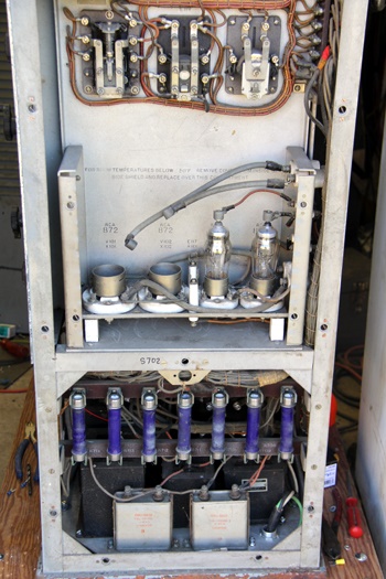
Earle Smith VE6NM remembers one of the AT-3 quirks. "The IPA and PA
coils had a habit of getting gummed up to the point where the sliding pickup
rollers would jump off the coils when tuning. You were supposed to
shut down the transmitter, take off the side panels so the safety interlocks
would properly open, short the coils to ground for safety's sake, and put
the sliding roller back on the coil."
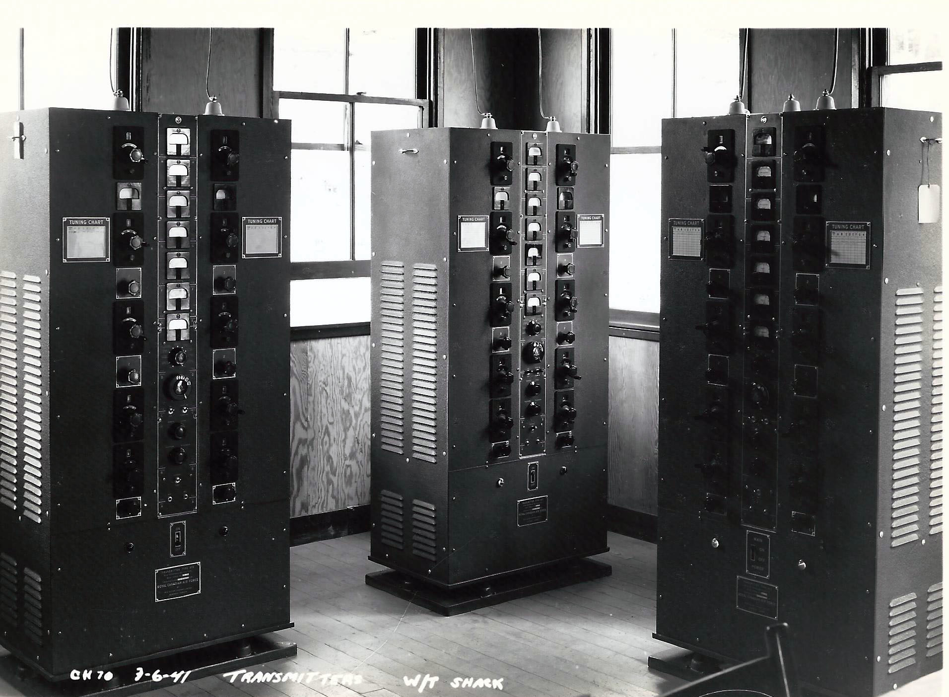 |
| Taken in 1941, this trio of AT-3 transmitters was part of a Canadian west coast W/T station. (From the collection of Fran Aitkens) |
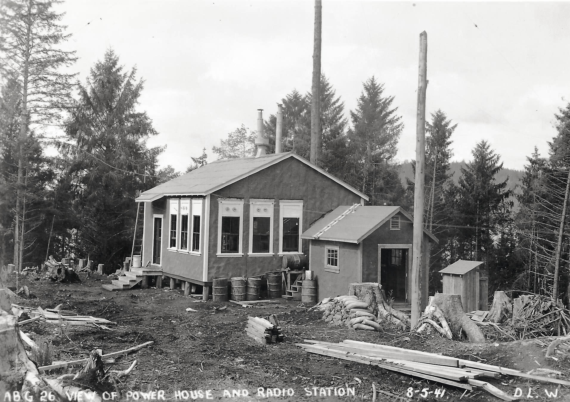 |
| An unidentified Canadian west coast W/T station. It sported a trio of AT-3 transmitters as shown in the previous photo. The transmitters were in the larger structure. Adjacent, was the power house, the smaller of the two structures. (From the collection of Fran Aitkens) |