1960's ERA EQUIPMENT
The 60's saw newer equipment and methodology being introduced
into the fleet starting with the Mackenzie class.
When this class of ship came into service, there was a radical change
in the layout of compartments. Gone, were the old Message Centre, Radio
1 and Radio 3. In place of these, the RCN designated a Communications Control
Room (CCR) which occupied the same area and included the majority of equipment
that used to be spread over several compartments. The CCR was designed
to simplify message handling and control of radio equipment. No longer
did the chief radioman have to send a man to a specific compartment to
tune a transmitter. With the exception of some low frequency transmitters,
all radio sets were close at hand in the CCR Personnel could work side
by side with a minimum of wasted movement.
The introduction and use of SSB voice communications was a technical
innovation for the navy and there were very sound technical reasons for
wanting to do this. The principles of SSB were known as early as 1915 when
SSB was first used on landline "carrier" equipment for frequency-division
multiplexing of up to four telephone circuits on one wire pair.
In 1928, the very first radio trial of SSB began on VLF but the problem
was one of getting adequate vacuum tube
power amplification. A four voice-channel SSB HF link was established
between the Netherlands and the Netherlands Antilles in 1934 which proved
it could be done and remain in service 24/7. Up to around 1950 there had
been little work done on single-channel SSB for any radio service due to
frequency stability problems however developments such as highly stable
variable oscillators and the Collins mechanical filter made SSB not only
practical but economical thus opening up this new mode.
The reasons for wanting to shift from AM to SSB are listed below:
A fully modulated AM signal has two thirds of its power in the carrier
and only one third in both of the sidebands. In AM, the carrier is used
to deliver the audio intelligence to the detector of the receiver and is
then discarded. Each of the two side bands carry an identical copy of the
audio intelligence. Why not suppress the carrier and one sideband ? This
is precisely what is done in SSB transmission. Here are the advantages
to be realized: * Heterodynes are eliminated at the receiver as no carrier
is being transmitted.
* Since only one side band is being transmitted, the signal only takes
up one half of the spectrum space occupied
by an equivalent AM signal.
* Since only one side band needs to amplified in the transmitter, the
final amplifier can be made to run more
efficiently.
* Studies have shown that is possible to achieve gains of up to 9 decibels
over AM.
* SSB is more readable than AM under more adverse receiving conditions.Other
innovations which followed, were improved UHF communication systems that
included a common antenna and multicoupler; a broadband MF/HF common transmitting
antenna and coupler system; facsimile recorders and lastly, VHF FM transceivers
for communication with merchant vessels.
ST. LAURENT CLASS RADIO CONFIGURATION
This extract came from the commissioning day pamphlet for HMCS Fraser:
"HMCS Fraser, a ST LAURENT class destroyer had three radio rooms for
for transmitting and receiving on low, medium, high, very high an ultra
high frequencies. A fourth radio room was used for Direction Finding. A
Message Center was equipped with teletype machines and a cryptographic
room for coding/decoding messages.
When commissioned , she had 12 separate telephone systems including
lines for docking ship, damage control, radar maintenance and refuelling
at sea. Also included were 12 sound broadcast systems. A radio remote control
system made it possible to broadcast or receive from any one of 28 positions
throughout the ship.
For electrical power, Fraser was fitted with five alternators capable
of producing 1,400 kilowatts of AC power".
EQUIPMENT DESCRIPTIONS
| AN/SRC-504
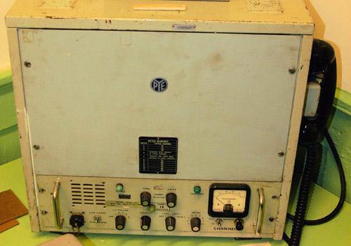
This was a low power VHF/FM transceiver made by Pye Electronics in the
UK. Consisting of one transmitter and two receivers, it provided line of
sight ship-to-ship or ship-to-shore communications for harbour, docking
or pilot service. It could also be used to monitor Channel 16 international
distress frequency on Channel 16. Twenty eight channels are available
with 50 KHz spacing.
Frequency Range: Transmitter - 156.05 to 157.40 MHz
Receiver A - 156.30 to 157.80 MHz
Receiver B - 160.65 to 162.00 MHz
Transmit power output: 10-12 watts. |
| AN/SRT 502 Transmitter
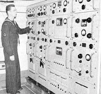 The SRT-502 was a replacement for the PV500 LM and PV500HM2. It was designed
primarily for ship-to-shore or ship-to-ship communications. Included in
the set, were two HF transmitters (3 to 28 MHz) for long distance work
and one low frequency unit (100 to 550 kHz) for shorter distances. All
three transmitters shared a common power supply. Modes of operation were
CW, R/T and RATT, however, the LF transmitter was not designed for R/T
operation and it also ran at a lower power level than its HF counterpart.
The high frequency transmitter was capable of producing a power input
of 1000 watts in high power operation, or 300 watts in low power mode.
Internally, the HF amplifier employed two 4-400A tubes in parallel, while
the LF amplifier employed a pair of 4-125 tubes. Any two transmitters could
be operated at the same time with high power input or alternatively, all
three transmitters could be operated in low power mode. (RCN photo taken
aboard HMCS Restigouche while in Halifax Harbour around 1960/61. Manning
the controls is ex-LSRM2 David Blais 36684-H )
 |
| This example of the SRT-502 transmitter is held by the MARCOM Museum,
Halifax. (Photo by Sandy McClearn) |
Per BRCN 213,, the following crystals
were available for use with the AN?SRT-502. |
| AN/URC 32 Transceiver
 This SSB transceiver was the first of its type to be installed in the fleet
and superseded the Marconi CM11. It was primarily designed for single sideband
transmission and reception on upper sideband, lower sideband or two independent
sidebands with separate audio and IF channels for each side band in the
range of 2 to 30 MHz. Other modes of operation included AM, CW, or FSK.
The equipment provided its own accurate and stable frequency control in
addition to external frequency control. Pictured above is the standard
URC-32 set as depicted in the RCN Trade Group 1 manual. Here is a summary
of the URC 32 operating and power modes. (RCN photo)
| Mode |
Description |
Power Input |
| A1 |
CW telegraphy |
500 watts |
| A3a |
SSB, reduced carrier |
500 watts |
| A3b |
Two independent side
bands; reduced carrier |
500 watts |
| A9 |
Composite transmission |
500 watts |
| A9a |
SSB; full carrier transmit |
125 watts |
| F1 |
Frequency shift telegraphy |
500 watts |
Tom Brent of Abbotsford, BC has studied the radio fittings in Mackenzie
class ships and offers some insight on URC-32 variants. "When I got on
board HMCS Mackenzie, Yukon, and Saskatchewan in the 1990's, the AN/URC-32
setup was different from what is depicted in the URC-32 photo above. Qu'Appelle
was based on the East coast but a manual indicates the URC-32 radio fit
was identical to the other three ships in the class.
While there were URC-32's in CCR (Command and Control Room) , they were
of the OA-5079/URC-32 variant which is essentially the standard URC-32
less the RF Amplifier section. When transmitting, the low level output
from these OA-5079/URC-32's was fed down two decks into the ship's transmitter
room where there were five AN/SRA-502 amplifiers. These broadband "no tune"
amps had a rating of 1000 watts PEP or 700 watts with a steady CW signal)
and used sixteen 4CX250B's. The amplifiers were Remotely controlled
by using the Panel Indicator SB-5053A/SRA-502A which was mounted at the
top of URC-32 rack in place of the standard RF amplifier section. It provided
indication of SWR and power output and allowed the operator to control
input (AC) power, operate/standby switching and reset the AN/SRA-502 in
the event of an overload.
The RF output from the SRA-502 amplifiers was fed into CU-714/SRA-22
antenna couplers which could match longwire antennas or a 35 foot whip.
These SRA-22's were also controlled from the URC-32 rack by way of coupler
control C-2698/SRA-22. In the URC-32 photo, it is the rack near the
top with the three meters. |
| AN/URR501 Receiver
 A general purpose AM receiver (Racal RA17) with a tuning range of 980 Kcs
to 30 Mcs. It could be tuned down to 500 kcs, but the performance of the
receiver was degraded in this range. It was the successor to the CSR5A
receiver. (RCN Photo)
|
| AN/URR502 Receiver
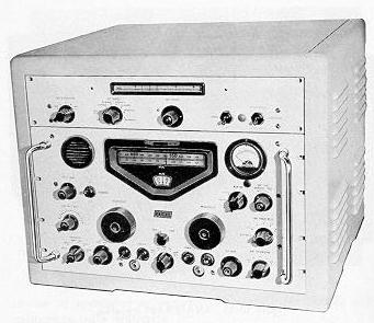 This was basically a URR501 receiver fitted with a low frequency RF converter
(CV5046) to extend the frequency coverage down to 12 kHz. It was the successor
to the RAK receiver. (RCN Photo)
|
| SRR RECEIVER
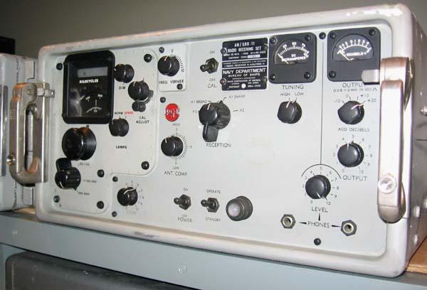
The use of the SRR series receiver by the RCN is confirmed by a photo
taken in HMCS Bonaventure's CCR. There, it was part of a RATT bay. Pictured
is an example of the SRR-11 (Photo by Tom Brent)
Tom Brent provides a description of the SRR receiver series. "This receiver
is a member of the AN/SRR-11/12/13 family of receivers designed by RCA
for the US Navy in the early 1950's. These sets covered 14-600 kHz (SRR-11),
0.25 - 8.0 mHz (SRR-12) and 2.0 - 32.0 mHz (SRR-13). The one shown in the
photo must be the AN/SRR-12 or AN/SRR-13 since the AN/SRR-11 has less knobs.
I have both the '11 and '13 in my shack; the SRR-12 however, is quite scarce.
It appears that the design may have been rushed a little to get these receivers
into production during the Korean war since a number of collectors report
calibration problems with early production units. In general, they are
a bit difficult to service due to their modularized design employing sub-minature
tubes with wire leads which are soldered in place. The lack of extender
cables also makes servicing somewhat of a headache.
The shore based version of these sets are known by the designation
AN/FRR-21/22/23. The only difference I have noticed is the addition of
19 inch rackmount brackets on the side of the case. I have owned a number
of the AN/SRR-13A (and FRR-23A) sets and all have had a 2 section Collins
mechanical filter in them. The bandwidths are 1.0 and 3.0 kHz and the IF
frequency is 200 kHz.
RCA had quite of number of contracts with the US Navy for top-of-the-line
communication receiver families starting with the RAA and RAB in the early
1930's, RAK and RAL (mid 1930's), RBB and RBC (1940) and the AN/SRR sets
in 1950. Personally, my favourites are the RBB/RBC's." |
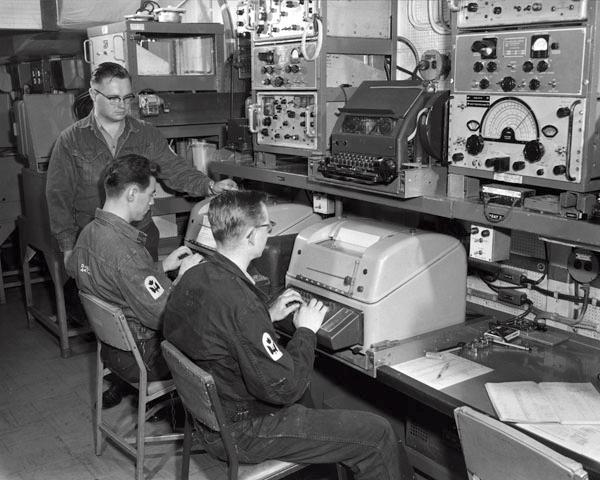 |
| Teletype bays in the Communications and Control Room (CCR ) aboard
the aircraft carrier HMCS Bonaventure. (Photo # BN-4100
courtesy DND, Canadian Forces Joint Imagery Centre provided via by Robert
Langille) |
AN/URA17 Converter
A transistorized frequency shift converter which superseded the FSC
107. It was designed for frequency diversity radioteletype broadcast reception
and single/dual channel reception.
CU-5032/URR Antenna Coupler
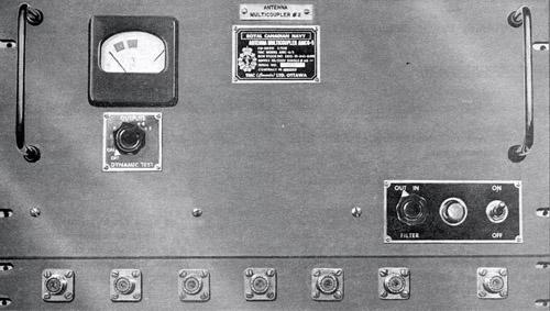 |
CU-5032/URR Antenna Coupler. AMC 6-5/70. (Photo courtesy
RCN)
Frequency Range: 2 to 30 MHz
Outputs : Six ; 70 ohms impedance each .
Primary Power Requirements:115/230 volts, 60 cps, 1 phase, 150 watts
Physical: 8-3/4 in H x 19 in W. x 12 in D.; Weight 46 lb.
Manual: BRCN 4134 |
The AN/CU-5032/SRR is a broadband amplifier consisting of a
detachable, low-noise, push-pull, pre-amplifier; a low-frequency, cut-off
filter; two distribution lines; six push-pull, isolation amplifier output
stages; a test oscillator and metering circuit, and a power supply.
Signals at the antenna input are amplified by the pre-amplifier and
fed through the distribution lines to the six power amplifiers. Each power
amplifier provides an output for a receiver. The low frequency filter is
effective in the broadcast band and may be switched in or out as desired.
The test oscillator and metering circuit permit each output stage to be
checked for overall performance.
AN/URT7 VHF Transmitter
This was a general utility VHF transmitter and looked very similar to
the AN/URT502 transmitter. It had a frequency range of 115 to 156 MHz with
a power input of 30 watts. There were four crystal controlled channels
available, but in an emergency, a master oscillator could be used. Normally,
the URT7 was used in conjunction with the AN/URR21 (RCK) receiver and was
the successor to the TDQ transmitter. In addition, there was a variety
of commercial transceivers fitted to cover the Maritime Mobile VHF band.
Prior to 1968, the RCN used a VHF 'intercom' in Halifax harbour which
also included the Admiral's office. The last two letters of the ship's
call sign was used for identification. It was an excellent system, but
it could not be used today, since the last two letters of a call sign may
be common to several ships.
| D649/K649 MuFAX Chart Recorder
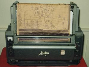 Manufactured by Muirhead, UK, this is a chart recorder used for the reception
of meteorological weather maps and wire photos by radio. The MUFAX audio
input signal was usually provided by an R1051B receiver. In the MUFAX,
audio was converted to current pulses which passed through a helix, across
the paper to the writing edge. Chemically treated paper would be marked
each time a current pulse was applied to the helix. When scanning was completed,
a viewable picture was produced. The D649 chart recorder was used as far
back as 1956 aboard HMCS Labrador. Because the MUFAX paper was impregnated
with chemicals, it was sometimes stored in the cook's refrigerator abroad
ship. This would prevent the paper from deteriorating. This machine was
widely used in the Canadian Forces and the Coast Guard. (Photo by Jerry
Proc)
|
Jacques d'Avignon VE3VIA, provides some background information
on the MUFAX. "These machines were manufactured by Muirhead in the UK and
first appeared in Canada when the Muirhead equipment was chosen to equip
weather offices across Canada with facsimile equipment.
In the early 1950's (1954 or 1955) the Department of Transport,
who operated the weather service at the time, needed a facsimile circuit
that would cover the country and enable all the weather offices to receive
the same weather maps compiled by a central office. This office,
called the Central Analysis Office, was located in a temporary building
at Dorval airport in Montreal.
CN (Canadian National) telegraph was tasked to implement this fax circuit
using their existing long lines across Canada. Muirhead equipment
was chosen for the recorders and scanners for this circuit. To serve
the Arctic weather stations (Resolute Bay, Frobisher and a few others),
two radio transmitters were also used; one transmitter was located in Edmonton
and one in Montreal".
Radio facsimile is slowly disappearing with more and more stations being
closed every year. As of 2009, CFH was still broadcasting weather
charts to the Atlantic but that came to a sudden end in November 2010.
The January 2011 edition of Monitoring Times reports that the Canada Navy
suddenly closed down its WEFAX/RTTY facility which sent weather data broadcasts
on the well known frequencies of 122.5, 4271, 6496.4, 10536, and 13510
KHz.
CFH broadcast radiofacsimile weather charts at the top of the
hour, then filled in the rest of the time with radioteletype text. The
sudden disappearance of weather FAX and radioteletype text transmissions
among military users is typical . As soon as everyone finally has
the latest satellite gear installed, it’s bye-bye to old technology.
At least for now (November 2010), RTTY transmissions are still
being sent from CFH. The most commonly reported frequencies are approximately
5097, 10945, and 15920 kHz.. Messages are sent at 75 baud and employ an
850 Hz shift. All channels idle on the mark tone, with the following marker
transmitted every thirty seconds: “NAWS DE CFH ZKR F1 [frequency list]
AR.” NAWS is a collective all-vessels call sign meaning Notice to Allied
War Ships. ZKR is a military procedural signal meaning “I am maintaining
a watch on… [frequencies].” AR, of course, means “end of message.”
SSB EXCITER
TMC, more than any other manufacturer, designed equipment with
a "building block" configuration. In other words, you could take a basic
AM/CW receiver and add a SSB converter; if you wanted space diversity capability,
you added a second receiver that could be controlled by the first one,
RTTY converter?....no problem.
TMC SBG-1 (a.k.a. AN/URA-30) is a 0 to 1 watt Single Sideband
Generator. The model number refers to full 19" rack of equipment
comprising of the following units:
CBE-1 (O-714/URA-31) Sideband Exciter
CHG-1 (AM-2505/URA-31) Frequency Amplifier
CMO-1 (O-716/URA-31) Controlled Master Oscillator
CLL-1 (O-717/URA-31) Controlled Oscillator
CHL-1 (CV-928/URA-31) Divider Chain
CSS-1 (O-715/URA-31)
CPP-5 Power Supply (for CHG-1) - Note: CPP-5 will not be present if
CPP-1 (PP-2561/URA-31) is mounted on back of the frame.
CPP-2 (PP-2562/URA-31) Power Supply
A similar rack full of equipment supplied with everything above EXCEPT
the CBE-1 Sideband Exciter is known as TMC Model CPO-1 (AN/URA-31) Controlled
Precision Oscillator. According to the April 1966 TMC catalogue, the price
for the SBG-1 was $11,875. The SBG-1 was normally used as the exciter for
a large transmitter such as the TMC SBT-1K (Sideband Transmitter, 1 kw),
GPT-10K (General Purpose Transmitter, 10KW), GPT-40K (General Purpose Transmitter,
40 kiloWatt), etc. It was this big because this was the only way to generate
a low level signal with the stability rated at 1 part in 100,000,000 in
the 1960's.
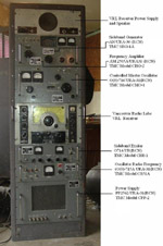 |
The rack in the photo belonged to a deceased
ham. Click to enlarge. The Vancouver Radio Labs VRL receiver is not part
of the TMC sideband generator kit. The units mounted in this rack are featured
below. (Photo via Andre Guibert) |
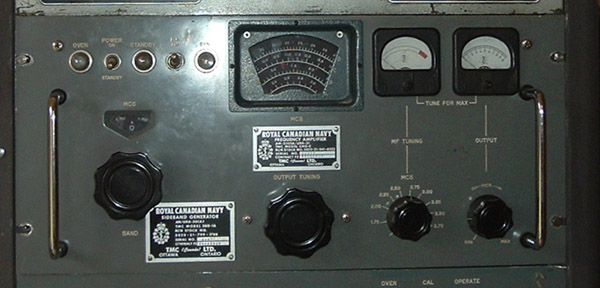 |
| Frequency Amplifier Model CHG-2 (from the smaller tag)
The larger tag is the system identifier. |
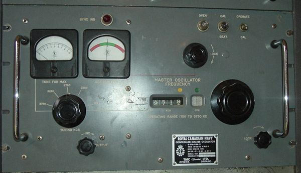 |
| Model CMO-1 Controlled Master Oscillator |
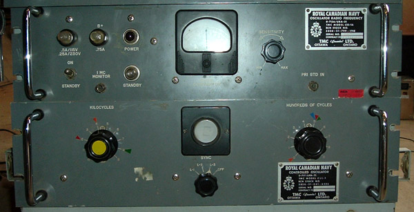 |
| Top unit: Model CBE-1 Sideband Exciter. Bottom unit: Model
CSS-1 RF Oscillator. |
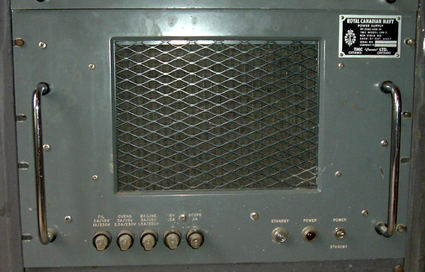 |
| TMC Model CPP-2 Power Supply. |
| All photos in this table via Andre Guibert |
EQUIPMENT LIFE
Like any piece of equipment, a radio set has a finite life
expectancy with the military. As a general rule, this expectancy is twenty
years. Like any other system, advances are continuously being made, however,
it is not always desirable to incorporate such advances in military communications
systems. The major reason for this is the cost of procurement and proof
of reliability of new systems. Radio equipment provides continuing service
in peace and in war. New radio systems are seldom fitted purely for the
sake of improvement unless there are changes in NATO requirements, Canadian
federal radio regulations, or amendments to International regulations.
In 1969, the RCN considered the following gear (specific to HAIDA) to
be obsolete: AN/URR35 UHF receiver, CM11 transmitter, CPRC26 portable radio,
CSR5A receiver, FSC107 frequency shift converter, FR12 D/F receiver, Model
14 T-D, Model 15 Teleprinter, MSL5 LF receiver, PV500 HM transmitter, and
the TED3 UHF transmitter. In this time period, much of the existing UHF
gear faced obsolescence because it required a continuous supply of crystals,
did not have a rapid tune facility, did not have 50 KHz channel spacing
and suffered from a high failure rate.
By 1978, the typical radio configuration aboard a destroyer was five
URC 32's, seven WSC 510's, seven Racal receivers and an SRD 501.
MORSE CODE
Morse code was an important means of communication right into
the early 1990's.
The basic keying method for sending automatic Morse in both the RCN
and USN was the Wheatstone tape which could be run at various speeds.
In the RCN, it was used for fleet broadcasts as well as the time honoured
SBX's. Wheatstone tape was the "format standard" of its day. McElroy, Teletype,
Kleinschmidt, Boehme and Creed were among the principal
manufacturers of Wheatstone reperforators.
Wheatstone tape was about 1/2" wide, made by McElroy and had the
same texture as the paper tape used for teletype transmission. The
configuration for dots and dashes consisted of two hole pattern.
To represent a dot, two holes were punched one above another and on either
side of the sprocket holes. The dash was a single hole on the
top line with the bottom line unpunched, followed by a single hole on the
bottom line with the top unpunched. Spaces between characters was
a measure of unpunched tape. The output tape would then be fed to a
keying
head for transmission.
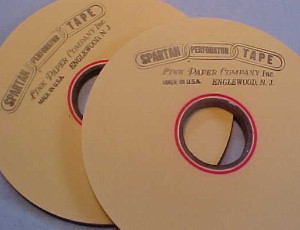 |
| This is blank tape for Kleinschmidt, Creed, McElroy and similar perforators.
It is about 0.47" wide; the roll is 8" in diameter with a 2" center hole.
Spartan was a supplier of tape for reperforators but was not involved in
the business of manufacturing them. (Photo courtesy of Artifax Books) |
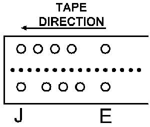 |
| A section of Wheatstone tape representing the letters J .--- and E
. (Graphic by Jerry Proc) |
 |
| This sample of standard Wheatstone tape shows a CQ calling sequence.
(Photo
by Chuck Swiger)
The characters are formed as:
Dash = upper hole punched, corresponding bottom hole unpunched,
next upper hole unpunched, corresponding lower hole punched. Dot
= upper and lower holes both punched.
There were varying configurations of Wheatstone punching. One
of the RCN's variations was dash as upper hole punched and next lower hole
punched. |
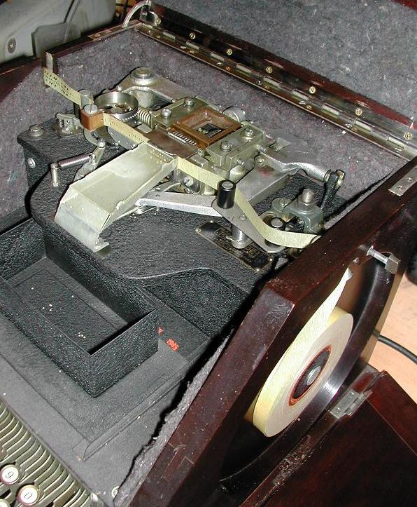 |
| A Teletype Corporation Wheatstone reperforator. Note the chad chute
and collector box down the front of the machine. (Photo by Chuck
Swiger) |
SBX TRANSMISSIONS
When ships were in harbour for long periods, such as a refit, the radiomen
copied Standard Buzzer Exercises (SBX's) to maintain their expertise. If
the radio equipment was functional, they copied Morse exercises from a
training frequency. If the radio equipment was unusable (lack of power
or landed maintenance), the men went to the 'morse pool' to maintain proficiency.
The Morse pool in Halifax and Esquimalt used low power transmitters to
serve the ships in harbour.
Allan Riley provides a detailed explanation of SBX's. "These SBX's were
sent at 22 wpm and consisted of a plain language message, a 40 group encrypted
letters message; a 20 group encrypted digits message and 5 short transmissions.
During World War 2, SBX's were similar in format except a foreign language
(usually French) message was also included.
Messages were broadcast to NAWS - a collective NATO call sign. The headings
of the messages were sent 'words twice'. SBX's were of the same format
as genuine messages, except for the operating signal ZEU which designated
them 'for exercise'. Z signals were used by themselves or in conjunction
with Q signals. The text of the encrypted (letters) message had the 'key'
letters in phonetics - the key, of course, showed how the rotors were to
be set in machine cipher. The "key" group in the 4 digit cipher was also
at the beginning of the text and repeated at the end.
The five short transmissions were used for practice in receiving procedure
signs, usually called prosigns. Call signs in the short transmissions group
sometimes consisted of 3 letter shore station call signs types or the 4
letter call sign types used by ships".
A document known as ACP 124 defined the formats and regulations for
the transmission and reception of radio telegraph messages and was used
by the NATO member nations until Morse Code was abandoned as a means of
communication. It focused on accuracy, speed and security and was last
upgraded to revision 'D' in 1983. On September 1, 1993 all CW related services
including training ceased to exist in the RCN.
ELECTRONICS MAINTENANCE
Jack Dennet of Orleans Ontario, describes the complement of
test equipment that was usually available aboard ship. "During the last
30 years, DDE and DDH class ships typically carried a Stark tube tester,
a frequency counter, audio and RF signal generators, multimeters and a
spectrum analyzer. It was just enough to get the job done.
In the period from 1963 to 1985, radio operators who initially trained
as operators at the Leading Seaman/Master Seaman level, were sent on Trade
Group 3 radio courses where they were trained as technicians capable of
carrying out first line maintenance when the ship was at sea. They were
responsible for keeping the gear in operational condition and worked long
hours to correct faults. A ship carried many replacement parts, however,
if a shortage was encountered, it was shipped to the next port of call.
Any equipment which could not be repaired was left unserviceable until
the ship arrived in home port and the dockyard technicians took over then.
As someone who has been involved with the new Canadian Patrol Frigate
program, things have changed greatly in the area of maintenance. Most repairs
are only taken down to the printed circuit board level. The technician
is aided by extensive fault finding flow diagrams as well as the built-in
diagnostic features. This approach reduces the down time of the equipment
and leads to a ship which is more operationally ready than we ever had
in the past".
Raymond Baines of Halifax N.S., recalls his experiences as a shipboard
technician. "My first ship as an electronics technician, was the Gatineau.
At the time, she was the most modern ship in the RCN. There was an electronics
workshop just opposite the Captain's cabin which was on the same level
as radar operations and Radar 1 and Radar 2 spaces. From that office, we
worked on radar problems and as I recall, Radio 3 which was the Electronic
Warfare office. For maintenance of communications gear, there was a bench
in Radio 2. Sonar had a similar setup for the tech assigned to that area.
We carried all the required test equipment and spares to keep the equipment
running for the duration of any voyage. If a critical part was required,
it was forwarded by whatever means necessary or we could borrow parts from
any NATO ship. All spares were cross- referenced with NATO part numbers".
COMMENTARY
Keith Kennedy of Surrey B.C. comments on the integration of the Canadian
Armed Forces in the late 1960's. " Ottawa, in its ultimate wisdom, decided
that radiomen were radiomen so they started sending army and air force
radio personnel to sea. They were trained as operators only and were not
versed in maintenance, could not do cipher work, were not seamen, and for
the most part, hated the job. After a period of chaos, the situation was
straightened around and it was recognized that seagoing radiomen were of
a different breed and no more Pongos or Pigeons were sent to sea. I really
felt sorry for these chaps because it sure wasn't the reason why they had
signed up with the Armed Forces. Eighteen years after integration, the
situation has nearly returned to the same point when the experiment was
started.
By 1975, Canada had withdrawn from the Commonwealth ship/shore system
for reasons best known to the Trudeau government. The workload for the
shore stations had diminished significantly and most communications employed
auto-ciphered teletype".
Keith goes on to comment about his final days in the service. "In 1985,
half way between Singapore and Bangkok, I decided that sea life wasn't
fun any more. I was getting too old to play this young mans game and the
living conditions at sea were wearing the body down. For these and other
reasons, I applied for my release. I have enjoyed my life as a sailor,
a seamen, and a sparker and would not trade my memories for the world,
but I must candidly admit that I do not yearn to relive or go back to the
sea as many of my contemporaries seem to do. I do not miss the navy life,
but at times I do miss the sea and especially, I miss my mates. If I have
learned anything from all those ships and all those years of service, I
suppose that go with the flow summarizes it best".
Over the course of decades the navy went through a series of name changes
for the radioman. Some of the different titles were: Communicator Radio;
Radioman; Communications Operator; Radop; Comop; Radioman Sea, then, Radsea.
Credits and References:
1) History of SSB http://www.sacmarc.org/archives/ssb.htm
2) Tom Brent <tgb(at)telus.net>
3) Robert Langille <ewcs(at)ewcs.ca>
4) Sandy McClearn <smcclearn(at)ns.sympatico.ca>
5) Jacques d'Avignon VE3VIA <monitor(at)igs.net>
Back to Table of Contents
Jun 22/20

 The SRT-502 was a replacement for the PV500 LM and PV500HM2. It was designed
primarily for ship-to-shore or ship-to-ship communications. Included in
the set, were two HF transmitters (3 to 28 MHz) for long distance work
and one low frequency unit (100 to 550 kHz) for shorter distances. All
three transmitters shared a common power supply. Modes of operation were
CW, R/T and RATT, however, the LF transmitter was not designed for R/T
operation and it also ran at a lower power level than its HF counterpart.

 This SSB transceiver was the first of its type to be installed in the fleet
and superseded the Marconi CM11. It was primarily designed for single sideband
transmission and reception on upper sideband, lower sideband or two independent
sidebands with separate audio and IF channels for each side band in the
range of 2 to 30 MHz. Other modes of operation included AM, CW, or FSK.
The equipment provided its own accurate and stable frequency control in
addition to external frequency control. Pictured above is the standard
URC-32 set as depicted in the RCN Trade Group 1 manual. Here is a summary
of the URC 32 operating and power modes. (RCN photo)
 A general purpose AM receiver (Racal RA17) with a tuning range of 980 Kcs
to 30 Mcs. It could be tuned down to 500 kcs, but the performance of the
receiver was degraded in this range. It was the successor to the CSR5A
receiver. (RCN Photo)
 This was basically a URR501 receiver fitted with a low frequency RF converter
(CV5046) to extend the frequency coverage down to 12 kHz. It was the successor
to the RAK receiver. (RCN Photo)


 Manufactured by Muirhead, UK, this is a chart recorder used for the reception
of meteorological weather maps and wire photos by radio. The MUFAX audio
input signal was usually provided by an R1051B receiver. In the MUFAX,
audio was converted to current pulses which passed through a helix, across
the paper to the writing edge. Chemically treated paper would be marked
each time a current pulse was applied to the helix. When scanning was completed,
a viewable picture was produced. The D649 chart recorder was used as far
back as 1956 aboard HMCS Labrador. Because the MUFAX paper was impregnated
with chemicals, it was sometimes stored in the cook's refrigerator abroad
ship. This would prevent the paper from deteriorating. This machine was
widely used in the Canadian Forces and the Coast Guard. (Photo by Jerry
Proc)


